

Skyware Type 960 .96 Meter Class I and II Antenna System,Type 123 1.2 Meter Class I and II Antenna System Assembly Instructions Manual
Assembly Instructions
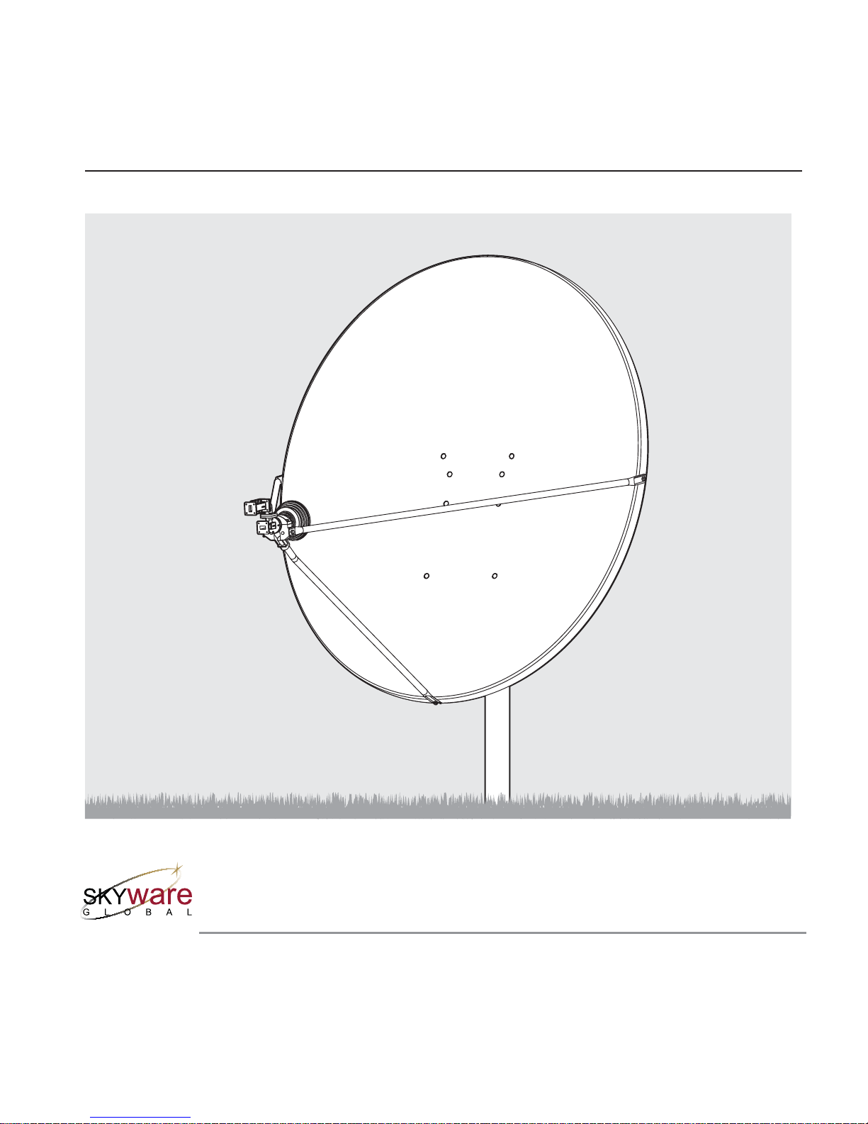
Type 960 .96 Meter Class I and II Antenna System
Type 123 1.2 Meter Class I and II Antenna System
with Factory Assembled Az/El Cap Mount
8000842-01
Skyware Global
1315 Industrial Park Drive
Smith eld, NC 27577 USA
Telephone: +1-919-934-9711
Internet: www.skywareglobal.com
Printed in U.S.A.
04/11 8000842-01 Rev G EC-01063
™

1
Skyware Global
VERY SMALL APERTURE TERMINAL (VSAT) PRODUCTS
TWELVE (12) MONTH LIMITED WARRANTY
Se ll er wa rr ant s t ha t a ll S k yw ar e Gl ob al ma nu fa ct ure d V SAT pr odu c ts are transferred rightfully and with go od title; that they are free from
any lawful security interest or other lien or encumbrance unknown to Buyer. Seller also warrants that for a period of twelve (12) months
from the date of shipm ent from Seller’s factor y, all its VSAT produ cts s hall b e fre e from de fects in mate rial a nd workmanship which arise
under proper and normal use and service. Buyer’s exclusive remedy hereunder is limited to Seller’s correction (either at its plant or at
such other place as may be agreed upon between Seller and Buyer) of any such defects by repair or replacement at no cost to Buyer,
except for the costs of any transportation in connection with the return of the defective VSAT products to be replaced or repaired, and
the costs to remove and/or reinstall the products, which shall be borne by Buyer. The limited warranty period shall not be extended
beyond its original term with respect to any part or parts repaired or replaced by seller hereunder.
This warranty shall not apply to VSAT products which (i) have been repaired or altered in any way so as to a ect stability or
durability, (ii) have been subject to misuse, negligence or accident, (iii) have been damaged by severe weather conditions such as
excessive wind, ice, storms, lightning, or other natural occurrences beyond Seller’s control; (iv) have presented damages, defects or
nonconformances caused by improper shipping, handling or storage, and (v) have not been installed, operated or maintained in
accordance with Seller’s instructions.
Buyer shall present any claims along with the defective VSAT product(s) to Seller immediately upon failure Non-compliance with any
part of this warranty procedure may invalidate this warranty in whole or in part.
SELLER MAKES NO WARRANTY, EXPRESS OR IMPLIED, OTHER THAN AS SPECIFICALLY STATED ABOVE. EXPRESSLY EXCLUDED
ARE ANY IMPLIED WARRANTIES OF MERCHANTABILITY OR FITNESS FOR A PARTICULAR PURPOSE. THE FOREGOING SHALL
CONSTITUTE ALL OF SELLER’S LIABILITY (EXCEPT AS TO PATENT INFRINGEMENT) WITH RESPECT TO THE VSAT PRODUCTS. IN
NO EVENT SHALL SELLER BE LIABLE FOR ANY LOSS OF PROFITS OR REVENUE, LOSS OF USE, INTERRUPTION OF BUSINESS, OR
INDIRECT, SPECIAL, CONSEQUENTIAL OR INCIDENTAL DAMAGES OF ANY KIND AS A RESULT OF THE USE OF THE
PRODUCTS MANUFACTURED BY SELLER, WHETHER USED IN ACCORDANCE WITH THE INSTRUCTIONS OR NOT. UNDER
NO CIRCUMSTANCES SHALL SELLER’S LIABILITY TO BUYER EXCEED THE ACTUAL SALES PRICE OF THE VSAT PRODUCTS
HEREUNDER.
In some jurisdictions, Buyer may have other rights under certain statutes that may imply non-excludable warranties. No representative is
authorized to assume for Seller any other liability in connection with the VSAT products.
DATE DESCRIPTION REVISION
08/06 ECN 9007484 Rev B
11/07 5075515 Rev C
05/08 5078314 Rev D
09/08 5075934 Rev E
01/10 654 Rev F
04/11 EC-01063 Rev G
MANUAL REVISION HISTORY
WARRANTY
DO NOT DISCARD CONTENTS
The product in this packaging was placed in the market after August 13, 2005. Its components must not be discarded with
normal municipal or household waste.
Contact your local waste disposal agency for recovery, recycling, or disposal instructions.

LAW: Installation and installer must meet local codes and ordinances regarding safety! Installation of this product should be performed only
by a professional installer and is not recommended for consumer Do-It-Yourself installations.
DANGER: WATCH FOR WIRES! Installation of this product near power lines is extremely dangerous and must never be attempted. Installa-
tion of this product near power lines can result in death or serious injury! For your own safety, you must follow these important safety rules.
Failure to follow these rules could result in death or serious injury.
1. Perform as many functions as possible on the ground.
2. Watch out for overhead power lines. Check the distance to the power lines before starting installation. Stay at least 6 meters (20 feet)
away from all power lines.
3. Do not install antenna or mast assembly on a windy day.
4. If you start to drop antenna or mast assembly, move away from it and let it fall.
5. If any part of the antenna or mast assembly comes in contact with a power line, call your local power company. DO NOT TRY TO
REMOVE IT YOURSELF! They will remove it safely.
6. Make sure that the mast assembly is properly grounded.
WARNING: Assembling dish antennas on windy days is extremely dangerous and must never be attempted. Due to the surface area of the
re ector, even slight winds create strong forces. For example, this antenna facing a wind of 32 km/h (20 mph) can undergo forces of
269 N (60 lb). BE PREPARED TO SAFELY HANDLE THESE FORCES AT UNEXPECTED MOMENTS. ATTEMPTING TO ASSEMBLE, MOVE OR
MOUNT A DISH ON WINDY DAYS COULD RESULT IN DEATH OR SERIOUS INJURY. Skyware Global is not responsible or liable for damage
or injury resulting from antenna installations.
WARNING: Antennas improperly installed or installed to an inadequate structure are very susceptible to wind damage. This damage can
be very serious or even life threatening. The owner and installer assumes full responsibility that the installation is structurally sound to support
all loads (weight, wind and ice) and properly sealed against leaks. Skyware Global will not accept liability for any damage caused by a
satellite system due to the many unknown variable applications.
WARNINGS
2
PRE INSTALLATION CONSIDERATIONS
TOOLS REQUIRED:
Compass 13 mm Deep Socket (3/8” Drive) 10 mm Nut Driver Torque Wrench
Clinometer #1 or #2 Phillips Screwdriver 10 mm Socket (3/8” Drive) 9” Magnetic Level
3/8” Drive Ratchet Wrench 13 mm Combination Wrench 10 mm Combination Wrench (2) 17 mm Open End Wrenches
ADDITIONAL INSTALLATION MATERIALS (Not Included with Antenna)
Installation Mount (Ground Pole, King Post, Wall Mount or Roof Mount)
Grounding Rod, Clamp & Grounding Block - As required by National Electric Code or local codes.
Ground Wire - #10 solid copper or #8 aluminum as required by National Electric Code or local codes (length as required).
RG-6 Coaxial Cables from antenna to indoor units.
Concrete: See “Ground Pole” section for quantity
M10 or #3 Rebar: See “Ground Pole” section for quantity. Deformed steel per ASTM A615, Grade 40 or 60.
SITE SELECTION
The rst and most important consideration when choosing a prospective antenna site is whether or not the area can provide an acceptable “look angle” at the satellites. A site with a clear, unobstructed view is preferred. Also consider obstruction that may occur in the future
such as the growth of trees. Your antenna site must be selected in advance so that you will be able to receive the strongest signal available.
To avoid obstructions, etc., conduct an on-site survey with a portable antenna. The satellite antenna can be installed on a ground pole,
wall/roof mount, or non-penetrating roof mount with 2-7/8” or 3” outside diameter mast. The chosen mount type should be assembled and
in place before installing the antenna. Refer to instructions packed with mount for its proper installation. The mast pipe must be vertical and
plumb to insure ease of alignment.
As with any other type of construction, a local building permit may be required before installing an antenna. It is the property owner’s
responsibility to obtain any and all permits.
Before any digging is done, information regarding the possibility of underground telephone lines, power lines, storm drains, etc., in the
excavation area should be obtained from the appropriate agency.
Because soils vary widely in composition and load capacity, consult a local professional engineer to determine the appropriate foundation
design and installation procedure. A suggested foundation design with conditions noted is included in this manual for reference purposes
only.
1.2 m
Antenna
3
7.3 cm or 7.6 cm
(2.88” or 3 .00” O.D.)
91.4 cm max.
(36”)
182. 9 cm
(72”)
102 cm
(40” )
#3 reba r
x diameter
of pier. Inser t through
hole in tube a nd center.
#3 Reba r
D
Minimum
Diameter
25 mm
to 51 mm
(1” to 2”) slope
for water run -o
Grade
Below
Frost L ine
182. 9 cm
(72”)
25 mm to 51 mm (1” to 2”)
slope for wa ter run-o
Grade
7.3 cm or 7.6 cm
(2.88” or 3 .00” O.D.)
D
Minimum
Diameter
Below
Frost L ine
Approx.
51 mm
(2”)
127 c m
(50”) (See Note)
#3 rebar x .46 m (18”)
Insert through
hole in tube a nd center.
#3 Reba r
#3 rebar x .6 m (24”)
at 60˚ apar t (S ee note)
51 mm
(2”)
Bubble
Level
Ground Pole Must Be
Vertical in All Directions
at Top
NOTE:
127 cm (50”) may
be increase d to frost
line. Concrete a nd
length of re bar will
increase
accordingly.
Bottom View
NOTE:
1. Poles are not supplied (purchase locally to above speci cations) and must be eld drilled 5/8” diameter
for M10 #3 rebar, 5.5 mm for self tapping grounding screw and (.218”) for 1/4-20 self tapping grounding screw. Poles and screws must
be galvanized or painted for protection.
2. Pole and foundation design based on the following criteria:
a. Uniform building code Exposure B or C wind loading.
b. Vertical soil pressure of 13790 kPa (2000 pounds per square foot).
c. Lateral soil pressure of 2758 kPa (400 pounds per square foot).
d. Concrete compressive strength of 17.2 MPa (2500 pounds per square inch) in 28 days.
3. See page 6 for grounding recommendations.
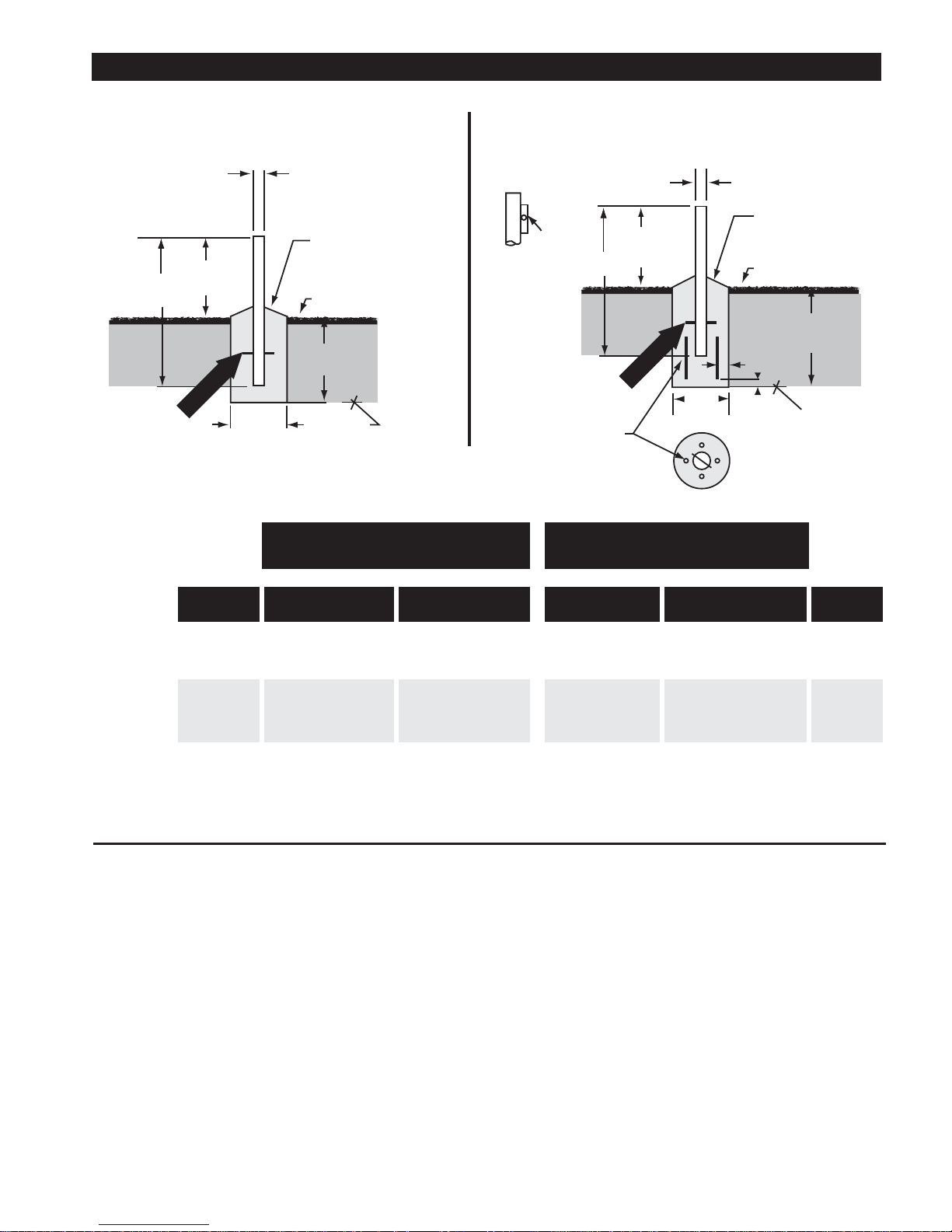
CAUTION: The foundation design shown does not represent an appropriate design for any speci c locality. Soil conditions vary and may
not meet design criteria given in Note 2. Consult a local professional engineer to determine your soil conditions and appropriate foundation.
GROUND POLE INSTALLATION
Pier Foundations Deep Frost Line Foundations
WIND VEL DIM D CO NC VOL DIM D CONC VOL DIM D CONC VOL DIM D CONC VOL GROUN D
km/h (mph) cm (in) m3 (ft3) cm (in) m3 (ft3) cm (in) m3 (ft3) cm (in) m3 (ft3) POLE
161 (100) 25 (10) 0.05 (1. 8) 38 (15) 0.12 (4.1) 18 (7) 0.03 (1.1) 25 (10) 0.06 (2.2) A, B or C
201 (125) 36 (14) 0.10 (3.7) 51 (20) 0.21 (7.4) 2 3 (9) 0.05 (1.9) 36 (14) 0.13 (4.6) A, B or C
161 (100) 30 (12) 0.07 (2.5) 46 (18) 0.17 (6.0) 20 (8) 0.04 (1.4) 33 (13) 0.11 (3.8) A ,B or C
201 (12 5) 43 (17) 0.15 (5.2) 61 (24) 0.30 (10.5) 30 (12) 0.09 (3.2) 48 (19) 0.23 (8.1) A or C
EXPOSURE B
96 cm
Antenna
EXPOSURE C
EXPOSURE B
EXPOSURE C
POLE SPECIFICATIONS:
Ground Pole “A” 2-1/2 Schedule 40 Steel ASTM A53 Pipe (73 mm x 5 mm Wall/2.88” OD x .203” Wall)
Ground Pole “B” 3.0” OD x 9 Gauge (.148” Wall) Steel ASTM A501 Pipe (76 mm OD x 3.8 mm Wall)
Ground Pole “C” 2-1/2 Schedule 80 Steel ASTM A53 Pipe (73 mm x 7 mm Wall/2.88” OD x .276” Wall)
91.4 cm max.
(36”)
Pier Foundations Deep Frost Line Foundations
The Az/El mount is factory con gured to achieve elevation angles from 8° to 54°. For higher angles, the elevation adjustment screw
setting must be modi ed. (See table for elevation ranges). Before proceeding with antenna installation, determine the elevation angle for
the site (refer to main installation instructions). If the elevation setting for the site is greater than ~ 52º, follow these steps:
Antenna Model Range As Shipped Range At High Angle Setting
1.2 m Type 123 8˚ to 54˚ 42˚ to 85˚
96 cm Type 960 8˚ to 54˚ 34˚ to 85˚
Adjustment procedure:
1 Loosen two elevation clamp nuts (in curved
slots), and loosen elevation pivot bolts
2 Swing the housing up against the
underside of the elevation adjustment
screw head
3 Set the az/el mount on the side closer to
the elevation adjustment bolt
4 Loosen the bottom nut on the elevation
adjustment screw. (Use two open-end
wrenches to release the double nuts)
5 Run the top nut up tight against the
az/el housing and elevation screw head,
then back o nut half a turn
6 Run bottom nut along the elevation screw
against top nut
7 While holding the top nut in place with a
wrench rmly tighten the bottom nut
against it to lock them both in that
position.
8 The az/el is now con gured for high
elevation angles. Proceed with the
installation as instructed in the installation
manual.
Bottom Nut Top Nut
High Elevation Angle SettingFactory Setting of Elevation Screw
Clamp Nut
(2 Places)
Elevation
Pivot Bolts
(2 Places)
Note new
position of top
and bottom nut.
Elevation
Pivot Bolts
(2 Places)
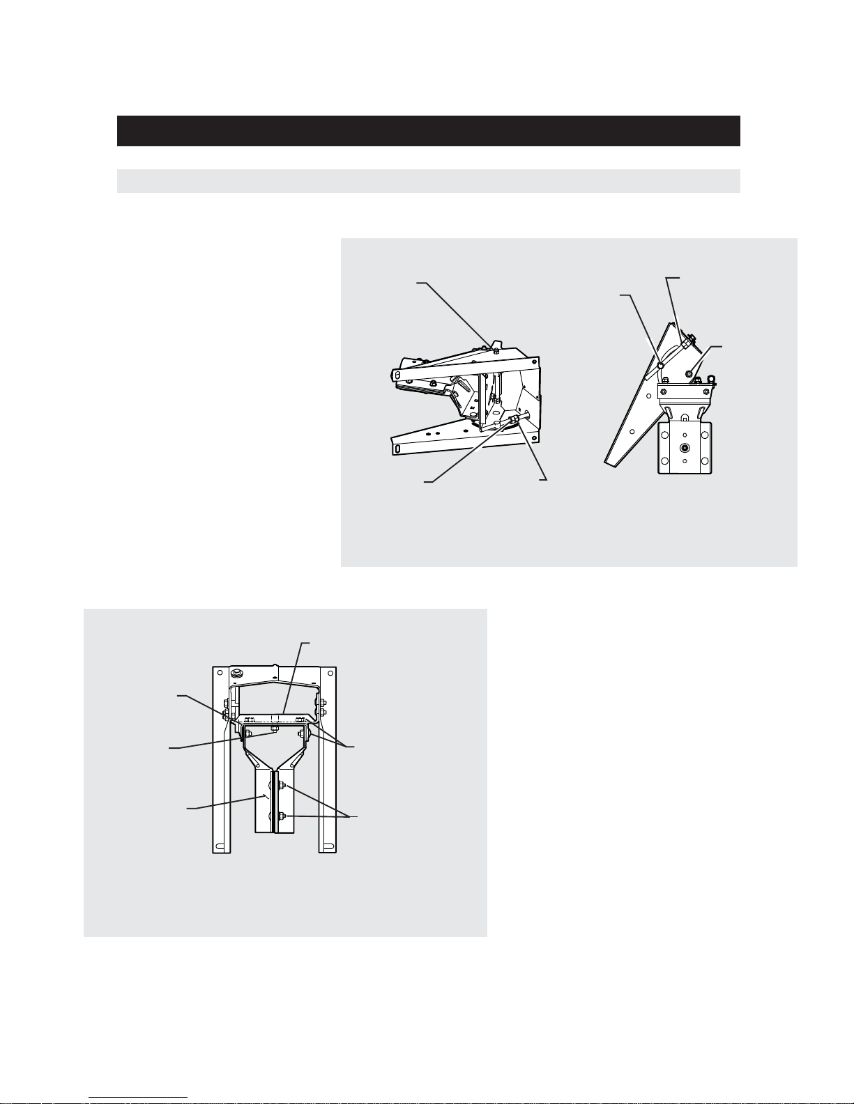
Top Bracket
U Bracket
Carriage Bolt
and Hex Nut
(4 Places)
Half Clamp
(2 Places)
Clamp Bolts
(Carriage Bolt
and Hex Nut)
(4 Places)
Hex Nut
Swivel Nut
Loosen (4) carriage bolts and nuts securing the
“U” bracket to the top bracket. Loosen (4)
carriage bolts and nuts securing “U” Bracket to
(2) half clamps. Loosen swivel nut and hex nut.
Install AZ/EL cap mount onto ground pole. Equally
tighten (4) clamp bolts so that cap is held stationary on ground pole, but can be swiveled with
slight pressure (approximately 2.7 N-m (2 ft-lb).
Retighten and torque (4) carriage bolts and nuts
securing “U” bracket to half clamps to 24.4 Nm
(18 ft-lb). Leave loose (4) carriage bolts, swivel nut
and hex nuts, for ne tune option.
4
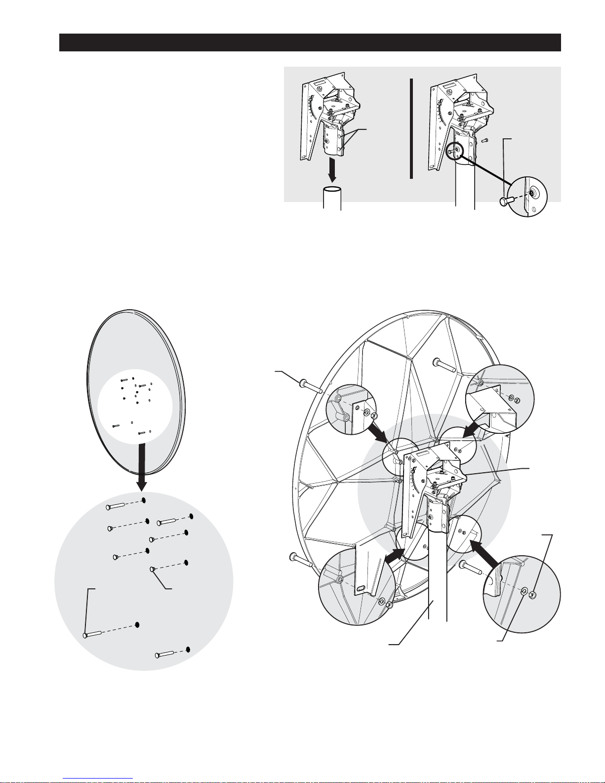
ASSEMBLY AND INSTALLATION
Assembling Re ector Onto Az/El Cap Mount
Install four M8 x 60 mm plow bolts into holes in re ector face. Lift re ector and insert exposed portion of bolt into holes in az/el mounting
ange. Secure re ector to az/el mount with 4 lock washers and hex nuts onto plow bolts. Tighten and torque to 15 N-m (11 ft-lb). Press t
hole plugs in remaining four unused holes of the re ector.
IMPORTANT: Note orientation of feed leg mounting holes in re ector rim. Top of re ector does NOT have feed leg mounting hole.
Az/El
Cap
Mount
Installation Pole
M8 x 60 mm
Plow Bolts
(4 Places)
Hex Nut
(4 Places)
Lock Washer
(4 Places)
M8 x 60 mm
Plow Bolts
(4 Places)
Hole Plugs
(4 Places)
Front View of Re ector Rear View of Re ector
5
Installing Az/El Cap Mount Onto Pole
Before installing az/el cap onto pole, installation mount
should be in place. Loosen (4) hex nuts on pipe clamp. Install
az/el cap onto pole. Equally tighten (4) clamp bolts so that
cap is held stationary on pole, but can be swiveled with
slight pressure. Tighten approximately 2.7 N-m (2 ft-lb ).
Insert (2) M8 set screws into threaded inserts in pipe clamp.
Do not tighten.
Back View
M8 Set
Screws
(2 Places)
Clamp
Bolts
(4 Places)
 Loading...