

Page 1
User’s Manual
Model
SWTC1200
______________
WARNING
Read all precautions and
instructions in this manual before
using this equipment. Save this
manual for future reference.
Maximum user weight 200 lbs
IMPORTANT
Trampoline and Enclosures are
susceptible to winds. Be sure to
secure your trampoline and enclosure.
Wind Damage is not covered in the
warranty of your trampoline
Page 2
ASSEMBLY
ASSEMBLY (PUTTING THE TRAMPOLINE AND ENCLOSURE TOGETHER)
IMPORTANT ASSEMBLY INFORMATION
• Need phillips screw driver (included with trampoline) and 2 adjustable wrenches (for putting the trampoline together). A rubber
mallet is also recommended to make assembly easier.
• Assembly requires two adults. Keep children away from the trampoline and enclosure until they are completely put together.
• Use gloves to protect your hands from pinch points during assembly.
• Make sure that the trampoline is properly put together, with the frame pad correctly laid out, before you put together the trampoline
enclosure.
• The assembly steps refer to parts by their descriptions and key numbers (see the PARTS LIST on page 13 and make sure that all
listed parts are included. If a part is missing, refer to ORDERING REPLACEMENT PARTS at the bottom of page 13.
TRAMPOLINE PLACEMENT
1. Place the trampoline and enclosure on a level surface before you use it.
2. Adequate overhead clearance is essential. A minimum of 24 feet (7.3 meters) from the ground is recommended. Provide clearance
from wires, tree limbs, and other possible hazards. Lateral (sideways) clearance is also essential. Place the trampoline and enclosure
away from walls, structures, fences, and other play areas. Maintain a clear space on all sides of the trampoline and enclosure.
3. Use the trampoline in a well-lighted area. If the trampoline is indoors or in a shady areas you may need to use artificial (electrical)
lighting in the area.
4. Secure the trampoline and enclosure against unauthorized and unsupervised use.
5. Remove any objects from under the trampoline and enclosure.
6. The owner and supervisors of the trampoline are responsible to make all users aware of practices specified in this manual.
7. The trampoline enclosure is only to be used as an enclosure for a specific round trampoline.
Trampoline Assembly
1. Make sure that you understand the information in the box at
the top of this page.
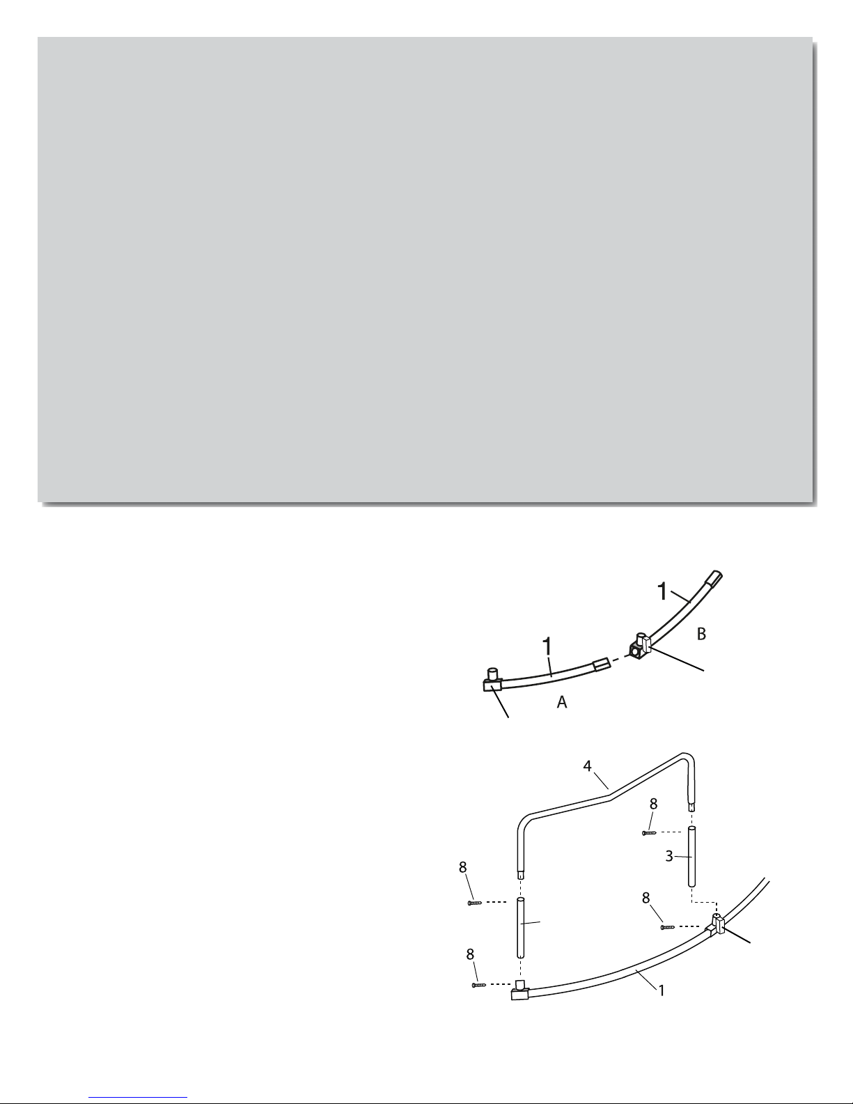
Lay two Top Tubes (1) (A with “T” -joint and B with Socket in
the insert drawing) on the ground in the positions shown. Make
sure the Top Tubes are turned so the small holes (spring holes)
are facing the ground.
Insert one end of the Top Tube with T-joint (A) into the Socket
of the other Top Tube (1) with Socket (B). The Top Tubes
should now appear as shown in step 2, below.
2. The peak of the Leg Brace should point toward the ground.
Insert Leg Extension (3) into the Leg Brace (4) secure
with screw (8). Insert Leg Extension (3) into Leg Brace
(4) secure with screw (8). Insert one Leg halfway into the other
T-joint. Pull out on other leg and insert into other Socket. Press
down on both Legs at the same time and fully insert them into
the T-joint and Socket tightened by screw (8).
Note: You may need to pull outward on the Legs as you insert
them into the T-joint and Socket. Leg warning sticker should face
out.
Socket
“T”-joint
3
Socket
Repeat steps 1 and 2 five additional times to assemble five
more leg sections.
13
Page 3
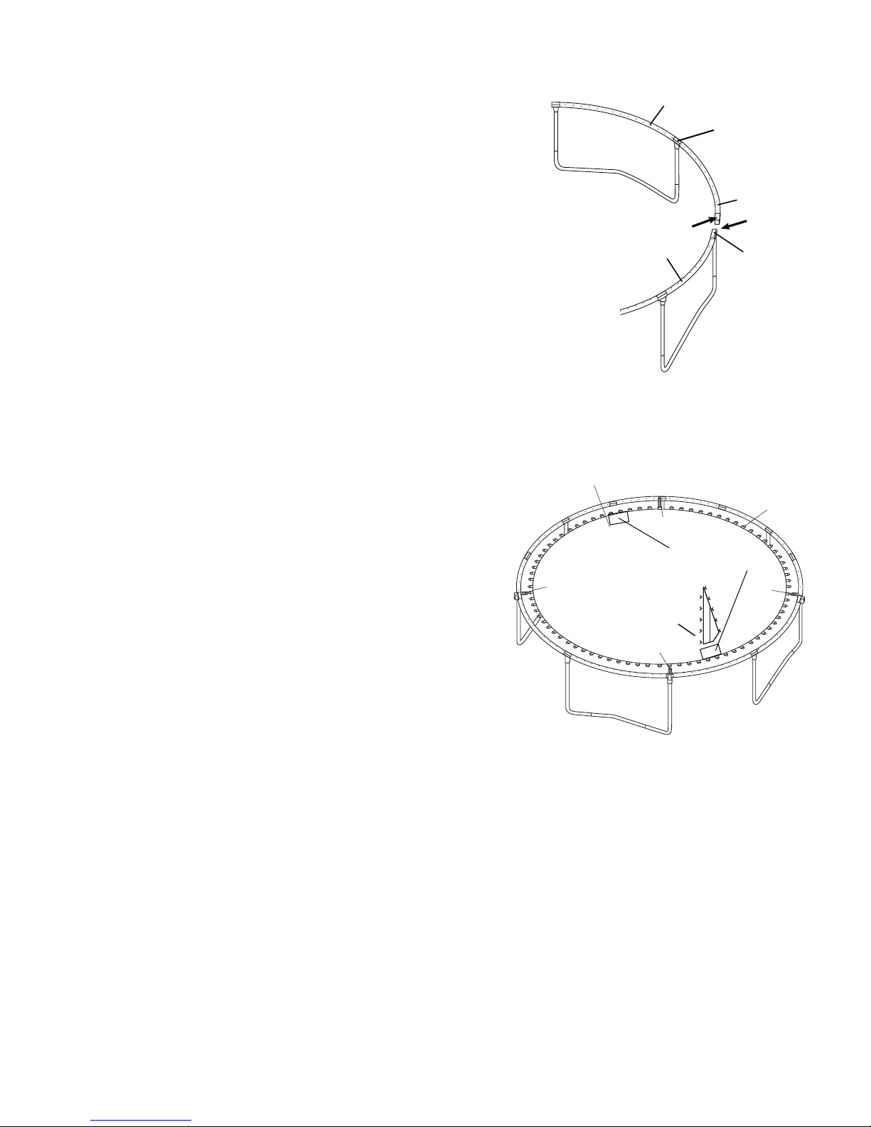
3. Note: This step requires two persons. During this
step, you will connect the six assembled leg sections with
the remaining six Top Tubes (1).
Leg Section
Stand two leg sections and hold them in the positions
shown. Slide the large end of one of the remaining Top
Tubes (1) onto the small end of the indicated Top Tube
on one of the leg sections. Insert the small end of the Top
Tube into the indicated Top Tube with T-joint (2) on the
other leg section. Repeat this step until all six leg sections
are connected. When this step is
completed,
the frame
will be fully assembled and freestanding.
4. Lay the jump mat (9) on the ground inside the assembled
frame. Make sure that the two warning decals are on
top of the Mat and are located in the center, between the
two legs of the trampoline as shown.
Put enclosure mesh
Insert one of the V-rings on the jump mat into one of the
"buttonhole" incisions on the bottom edge of the enclosure
mesh. Continue this process to the other V-rings one by one,
until all the V-rings are inserted though the “buttonholes”
of the enclosure mesh. Make certain that each of the V-
rings on the trampoline mat is threaded through the
corresponding 'buttonhole' in the enclosure netting,
and that the door opening of the enclosure is located near
the warning label of Jump mat.
If the enclosure was pre-installed on the Bed (Mat)
at the factory. Inspect the attachments of the enclosure
Netting to the trampoline mat (bed). Make certain each of
the V-rings on the trampoline mat (bed) is threaded
through the corresponding “buttonhole” in the Netting.
Be sure to place the door opening in the enclosure netting so it is centered in between the two legs of the trampoline where the jumpers will climb off and onto
the trampoline easily as shown.
(7) on the jump mat.
Leg Section
9
11
Align opening of enclosure
as shown here, centered in
between the legs of the
trampoline.
Socket
Small
End
11
Warning Label locate in the
center between the two legs
of the trampoline as shown
11
1
Large
End
“T”-joint
V-rings
11
Note: There are 72 V-rings around the edge of the Bed
(Mat) (9) and 72 holes around the top of the frame. In
Steps 4 and 5 you will attach the Bed (Mat) (9) to the
frame, using 72 Springs (11). Make sure your trampoline
mat (Bed) is in the correct position over the leg as shown
in the diagram.
Caution: It is wise to wear leather gloves while attaching the Springs. Be careful where you place
hands as the Springs and frame joints can pinch.
our
y
14
Page 4
9
V-rings
For mat, to have one Leg Extension (3) with warning decal corresponded to door of the net, the first hole
of the frame on the left of the net door is just the hole to
attach first spring (11).
Attach the Springs (11) as follows: Hook one end of a
Spring (11) into a V-ring. Hook one end of a Spring
(11) into a V-ring sewn on the Jump mat. Hook a Spring
tool (5) shown as the inset drawing in next page to the free
end of the Spring(11). Pull it by the spring tool(5) until it
reaches the frame. Push the end of the Spring into a hole
in the frame. Unhook the Spring tool.
Note:The spring has a large hook which attaches to the
frame and a small hook which attaches to the mat ring.
After you have hooked one Spring (11) into one of the Vrings on the Bed (Mat) (9), count exactly 18 V-rings and
18 frame holes in a clockwise direction. Attach a second
Spring to the V-ring and frame at this point. Count 18 Vrings and 18 frame holes in a clockwise direction and
attach a third Spring. Count 18 V-rings and 18 frame
holes in a clockwise direction and attach a fourth Spring.
5. After attaching the first four Springs (11), count exactly 12 V-rings and 12 frame holes in a clockwise direction.
Attach another Spring to the V-ring and frame at this
point. Count 6 V-rings and 6 frame holes in a clockwise
direction and attach another Spring. Count 6 V-rings and
6 frame holes in a clockwise direction and attach another
Spring. You will now have 6 evenly spaced Springs (11)
attaching the Bed (Mat) (9) to the trampoline frame.
11
Inset drawing
11
V-ring
11
11
5
11
5
Frame
Continue to attach the remaining Springs between the
previously attached Springs, until all Springs are
attached.
Safety Note: For the Bed (Mat) (9) to have the even tension necessary for safety in jumping, the Springs (11)
must be attached as described. As you attach Springs,
carefully count the V-rings and frame holes. If a V-ring
or hole is skipped, reattach the Springs in the proper
position.
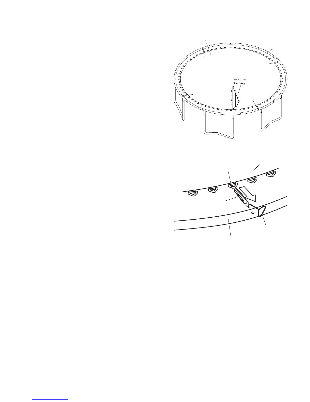
6. Lay the frame Pad (10) on the frame. Adjust the position of the Frame Pad so that the slits are directly above
the Socket, as shown.
15
Page 5

Do not use the trampoline without the Frame Pad (10).
The Frame Pad is designed to reduce the possibility of
injuries due to jumpers coming in contact with the trampoline frame. If you do not have a Frame Pad, contact
your dealer to obtain one. Properly install the Frame Pad
before using the trampoline.
Inner Straps
V-ring
7. Look under the trampoline and locate the straps
attached to the underside of the Frame Pad.
Position each outer strap so that one strap is tied on each
side of the frame as shown. One end of each inner strap
through the V-ring, then tied them up.
Refer to the inset drawing. Hold one of the straps. Wrap
the longer strap under the frame and then tie each end of
strap as shown. Pull tight to secure strap to frame.
Repeat this step with the remaining straps (not shown).
8. Using the included plastic tie, attach the Safety Placard
(12) to the frame near the point where jumpers will climb
onto and off the trampoline.
Cover the holes on the pad by the small covers sewn on the pad.
The trampoline is now fully assembled. Make sure that
all parts are securely attached. Familiarize yourself and
all users of the trampoline with the safety precautions,
use and instructional materials, and care and maintenance
instructions in this manual before using the trampoline.
Frame
Straps
DISASSEMBLY (TAKING APART)
To disassemble (take apart) the trampoline, follow assembly steps 1 through 8 in reverse order. Do not attempt to
disassemble any frame parts before the springs and the mat have been removed. Use gloves to protect your hands
from pinch points while taking the trampoline apart.
Socket
Socket
16
Page 6

Enclosure Assembly
1. Make sure that you understand the information in the
box at the top of this page.
2. Lay one Straight Tube (5) with foam and one Curved
Tube (6) with foam (8) on the ground, insert the Straight
Tube(5) into the curved tube(6), secure with the screw(4).
Repeat this step to attach the five remaining Straight
Tubes(5) and Curved tubes(6) together (not shown).
6
5
4
Inspect the attachments of the enclosure
3.
Netting to the trampoline mat (bed). Make certain each of
the V-rings on the trampoline mat (bed) is threaded
through the corresponding “buttonhole” in the Netting.
Be sure to place the door opening in the enclosure netting so it is centered in between the two legs of the trampoline where the jumpers will climb off and onto
the trampoline easily as shown.
17
Jump mat
7
Warning label
Opening of
the enclosure
V-ring
Page 7

4. Attach the Jump Mat to the trampoline frame by refer-
ring to steps 4-5 in the trampoline assembly
Be sure to place the door opening in the enclosure netting so it is centered in between the two legs of the trampoline where the jumpers will climb off and onto
the trampoline easily as shown.
3
Jump mat
7
Spring
Align opening of enclosure
as shown here, centered in
between the legs of the
trampoline.
V-ring
5. Attach the Frame Pad to the trampoline frame. Refer to
step 6-7 in your trampoline assembly for further instruction
Note: There is a Hexagon hole on the pole cap (1) with a nut
inside as shown A. Insert the pole cap(1) though one strap
ring on the top edge of the enclosure mesh(7) as shown in
Inset Drawing B. Make sure the Hexagon hole side of the
cap is against the mesh, and the holes on both the strap ring
and the caps are aligned.
Hold the pole cap close to a curved tube (6) with foam as shown
in Inset Drawing C. Insert the curved tube(6) into the pole
cap. Make sure the holes on the curved tube,pole cap
and strap ring are aligned. Insert the M5x50mm bolt(2)
until it touches the nut in the Hexagon hole of the pole cap,
securing them together.
Hexagon hole
1
Frame Pad
6
A
Trampoline
frame
6
7
Holes
Strap ring
Enclosure Door
Spring
B
Hole
1
1
2
Strap
Hole
Inset drawing
6
C
6
6
Repeat this process to assemble the rest of the pole caps(1)
to the curved tubes(6) with foam by the same manner.
18
Page 8

6. Note: In Step 6 you will secure the enclosure poles
to the frame of the trampoline.
Start from the enclosure door, lift one of the poles assembled
in Step 1, see the insert drawing. Insert the Straight Tube(5)
through frame pad into the top hole of the Square Socket on
trampoline frame as shown. Make sure the bent side of the
enclosure poles are facing toward the center of the trampoline.
Note: The end of the straight tubes(5) are sharp. Use
caution when assembling.
Repeat this process to assemble the remaining five poles
to the trampoline frame.
Poles
Enclosure
Door
Pad
7. Tie the straps that are sewn on the edge of the enclos-
ure mesh around the outside of the cap. Make sure to
secure the knot tightly, see insert drawing A..
Note: The enclosure poles are high, be careful when
you attach the straps. If needed, please use a ladder.
A
1
Strap
1
6
Strap
19
Page 9

8. Insert the end cap(3) into the bottom hole of the Socket.
Insert end cap (3) into end of Socket
9. Your trampoline enclosure is now fully assembled
(put together). Make sure that all parts are securely
attached. Familiarize yourself and all users with the
trampoline and enclosure with the safety precautions,
use and instructional materials, and care and maintenance instructions in this manual before using the
trampoline and enclosure.
DISASSEMBLY (TAKING THE ENCLOSURE APART)
To disassemble the trampoline enclosure (take it apart), follow assembly steps 1 through 8 in reverse order.
20
Page 10

WARNING
TRAMPOLINE AND ENCLOSURE CARE AND MAINTENANCE
Care
To avoid damage to the trampoline and enclosure, do not allow pets or animals inside the enclosure.
The trampoline is intended to be used by one person at a time who weighs not more than 200 pounds. The user
should be either barefoot, wearing socks, or wearing gymnastic shoes. Street shoes or tennis shoes should not be
worn on the trampoline. The user should remove all sharp objects from his or her person that may cause injury or
damage to the mat. Heavy, sharp, or pointed hard objects should never touch the mat.
Continued exposure over a long period of time to the sun, especially to ultraviolet rays, will shorten the life of the
enclosure fabric. For longer fabric life, store the enclosure when it is not being used. A dry enclosure, properly
stored, will provide the longest life of the fabric, sewing, and hardware. Remove the enclosure from the trampoline
during harsh weather conditions or during long periods of non-use.
MAINTENANCE
Your trampoline was manufactured using quality materials and crafted to provide you and your family with many
years of enjoyment and exercise. Proper maintenance and care will help to prolong the life of the trampoline and
reduce the possibility of injury. The following guidelines should always be followed.
Inspect the trampoline enclosure before each use, and replace any worn, defective, or missing parts. The following
conditions could represent potential hazards and increase the danger of personal injury:
• missing, improperly positioned, or insecurely attached frame padding, netting, enclosure tubes, or foam sleeves
• punctures, frays, tears, or holes worn in the mat, frame padding, netting or foam sleeves
• deterioration in the stitching or fabric of the mat, frame padding or netting
• ruptured or missing springs
• bent or broken frame, leg or enclosure tubes
• sagging bed or netting
• sharp protrusions on the frame, suspension system or enclosure tubes
If any of these conditions exist, the trampoline and/or enclosure should be
disassembled (taken apart) or otherwise protected from being used until the
condition is fixed.
SPECIAL CONSIDERATIONS
High Wind
It is possible for the trampoline and enclosure to be blown about by high winds. If you expect high winds, move the
trampoline and enclosure to a sheltered location. Disassemble (take down) the enclosure netting. Tie the trampoline
frame down to the ground using ropes and stakes (not included). At least three ropes and three stakes should be
used. Make sure to attach the ropes to the top of the trampoline frame: do not simply secure the legs or the bases to the
ground as they can separate from the frame sockets.The tops of the stakes should be at ground level so that they will not
create a tripping hazard. In addition, the tops of the stakes should be covered, if necessary, so that users will not be hurt by
falling onto the stakes.
Moving the Trampoline and Enclosure
If the trampoline and enclosure needs to be moved, it should be moved by two persons, kept horizontal, and lifted slightly.
If necessary, the trampoline and enclosure can be taken apart for moving. To take the trampoline apart, follow the assembly steps in reverse order (see pages 13 to 20). Do not attempt to take the frame sections, legs, or bases apart before the
mat and springs have been removed.
21
Page 11

EXPLODED DRAWING AND PARTS LIST FOR TRAMPOLINE
Key
No. Qty. Description
1 12 Top Tube(A with “T”-joint and
B with Socket )
3 Leg Extension
4 6 Leg Brace
5 1 Spring Tool
6 1 Screw Driver
* These parts are not illustrated.
Specifications are subject to change without notice.
12
Key
No. Qty. Description
8 26 (Two spare)
9 1 Stitched Bed with 72 V-rings
10 1 Frame Pad
11 72 Springs
12 1 User’s Manual and Safety Placard
* 1 Set of ASTM Frame Labels
9
wercS gnippat-fleS
10
11
6
5
3
1
4
12
8
ORDERING REPLACEMENT PARTS
To order replacement parts, visit our web site at www.skywalkertrampolines.com or call our toll-free Customer Care
Hot Line at 1-866-603-Jump (5867), Monday through Friday, 8 a.m. until 5 p.m. Mountain Time (excluding holidays). To help us assist you, please provide the following information when calling:
• the MODEL of the trampoline (see the front cover of this manual)
• the KEY NUMBER and DESCRIPTION of the part (see the PART LIST above)
• the quantity needed
• the desired method of shipping
22
Page 12

EXPLODED DRAWING AND PARTS LIST FOR ENCLOSURE
yeK yeK
noitpircseD.ytQ.oNnoitpircseD.ytQ.oN
1 6 Pole Cap
M5x50mm Bolt62
3 6 End Cap
w(1 spare parts)ercS gnippat-fleS74
ebuT thgiartS65
# These parts are not illustrated.
Specifications are subject to change without notice
1
2
6
6
6
7
9 1 Screw Driver
#
1
(screw driver included with
1
Mesh with straps
maoF128
6
ebuT devruC6
Trampoline parts )
launaM s’resU
7
6
4
5
6
5
9
3
6
5
5
8
ORDERING REPLACEMENT PARTS
To order replacement parts, visit our web site at www.skywalkertrampolines.com or call our toll-free Customer Care
Hot Line at 1-866-603-Jump (5867), Monday through Friday, 8 a.m. until 5 p.m. Mountain Time (excluding holidays).
To help us assist you, please provide the following information when calling:
• the MODEL of the trampoline (see the front cover of this manual)
• the KEY NUMBER and DESCRIPTION of the part (see the PART LIST above)
• the quantity needed
• the desired method of shipping
23
Page 13

LIMITED WARRANTY
Skywalker Holdings, LLC warranties its trampoline products to be free from defects in material and workmanship
under normal use and service conditions. The steel frame is warranted for one (1) year after the date of purchase. All
other parts are warranted for ninety (90) days after the date of purchase. Wind or weather damage is not warranted.
All warranty coverage extends only to the original retail purchaser from the date of purchase. Skywalker Holdings,
LLC obligation under this Warranty is limited to replacing or repairing, at Skywalker Holdings, LLC option, the
product at one of this authorized service centers. All products for which a warranty claim is made must be received
by Skywalker Holdings, LLC at one of its authorized locations. Preauthorization may be obtained by calling
Skywalker Holding, LLC Customer Care Hot Line at 1-866-603-Jump(5867). This Warranty does not extend to any
product or damage to a product caused by or attributable to freight damage, abuse, misuse, improper or abnormal
usage, or repair not provided by a Skywalker Holdings, LLC authorized service center, or to products used for
commercial or rental purpose. No other Warranty beyond that specifically set forth above is authorized by
Skywalker Holdings, LLC.
SKYWALKER HOLDINGS, LLC IS NOT RESPONSIBLE OR LIABLE FOR INDIRECT, SPECIAL OR
CONSEQUENTIAL DAMAGES ARISING OUT OF OR IN CONNECTION WITH THE USE OR
PERFORMANCE OF THE PRODUCT OR OTHER DAMAGES WITH RESPECT TO ANY ECONOMIC LOSS,
LOSS OF PROPERTY, LOSS OF REVENUE OR PROFITS, LOSS OF ENJOYMENT OR USE, COST OF
REMOVAL, INSTALLATION OR OTHER CONSEQUENTIAL DAMAGES. SOME STATES DO NOT ALLOW
THE EXCLUSION OR LIMITATION OF INCIDENTAL OR CONSEQUENTIAL DAMAGES. ACCORDINGLY,
THE ABOVE LIMITATION MAY NOT APPLY TO YOU.
THE WARRANTY EXTENDED HEREUNDER IS IN LIEU OF ALL OTHER WARRANTIES AND ANY
IMPLIED WARRANTY OF MERCHANTABILITY OR FITNESS FOR A PARTICULAR PURPOSE IS LIMITED
IN ITS SCOPE AND DURATION TO THE TERMS SET FORTH HEREIN. SOME STATES DO NOT ALLOW
LIMITATIONS ON HOW LONG AN IMPLIED WARRANTY LASTS. ACCORDINGLY, THE ABOVE
LIMITATION MAY NOT APPLY TO YOU. This Warranty gives you specific LEGAL RIGHTS. You may also have
other rights which vary state to state.
THIS WARRANTY IS VALID ONLY IN THE UNITED STATES.
Skywalker Holdings, LLC, PO Box 574, Brigham City, UT 84302 USA.
Printed in China © 2012Skywalker Holdings, LLC,
24
 Loading...