

Page 1
Assembly Installation, Care Maintenance
and User Instructions Manual
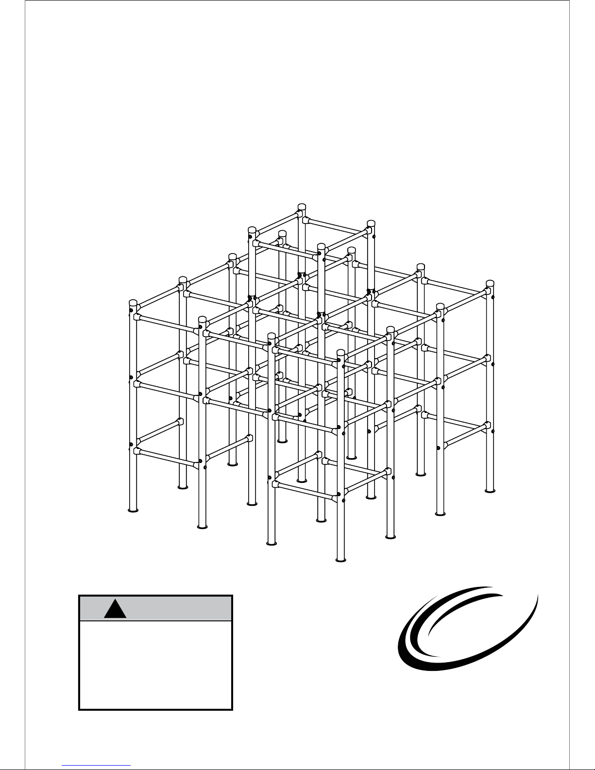
Jungle Gym Base Station
Model SJG200
WARNING
!
Skywalker Holdings LLC
P.O. Box 574, Brigham City, UT 84302
Model SJG200 Traditional Jungle Gym
Read all precautions and instructions in this manual before using this
equipment. Save this manual for
future reference.
Maximum occupancy 3 users.
Maximum weight capacity 243 lbs.
AGES 4 to 8
SKYWALKER
SPORTS
Page 2
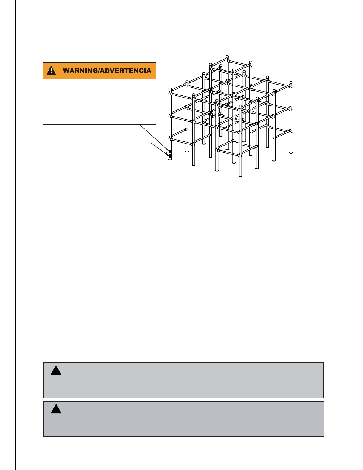
Model # Warning Label and ID label is located at the bottom base corner of the Jungle Gym
CONTENTS
Before you Begin . . . . . . . . . . . . . . . . . . . . . . . . . . . . . . . . . . . . . . . . . . . . . . . . . . . . . . ....................................................................3
Important Precautions . . . . . . . . . . . . . . . . . . . . . . . . . . . . . . . . . . . . . . . . . . . . . . . ....................................................................3
User Instructions . . . . . . . . . . . . . . . . . . . . . . . . . . . . . . . . . . . . . .. . . . . . . . . . . . . . . . . ....................................................................5
Jungle Gym Safety Information . . . . . . . . . . . . . . . . . . . . . . . . . . . . . . . . ....................................................................6
Using The Jungle Gym Safely . . . . . . . . . . . . . . . . . . . . . . . . . . . . . . . . . . ....................................................................6
Assembly . . . . . . . . . . . . . . . . . . . . . . . . . . . . . . . . . . . . . . . . . . . . . . . . . . . . . . . . . . . . . . . . . . ....................................................................7
Parts List ...................................... . . . . . . . . . . . . . . . . . . . . . . . . . . . . ...................................................................18
REPLACEMENT PARTS or QUESTIONS
If you have questions after reading this manual, please call our toll-free Customer Care Hot
Line. Our trained technicians will provide immediate assistance.
Customer Care Hot Line: 1-866-603-5867
Monday --- Friday, 8:00 am ---- 5 p.m. Mountain Time
WARNING
Read the assembly, installation, care, maintenance, and use instructions in this manual
prior to assembling and using this equipment. Save this manual for future reference.
2
( ID label location)
!
.....................................................................................................8
Pre-assembled part chart
Maintenance information..............................................................................................................20
Limited Warranty ..........................................................................................................................21
Exploded Drawing ......................... . . . . . . . . . . . . . . . . . . . . . . . . . . . . ...................................................................19
Playground surfacing materials information . . . . . . . . . . . . . . ....................................................................4
Age Grading: 4-8 years, maximum weight of 81 lbs.
Maximum Occupancy
7 children
SJG200 3 children
SJG201 2 children
SJG202 1 children
SJG203 1 children
The total maximum weight not exceed of 567 lbs.
(Warning label location)
N
WARNI
!
This product must be anchored. Anchors are sold separately
NG
Page 3

BEFORE YOU BEGIN
1. It is the responsibility of the owner and supervisors of this Jungle Gym Base Station to
make sure all users obey the safety instructions printed in this material.
2. This product is intended for use by children ages 4 to 8.
3. Use the Jungle Gym Base Station only as described in this manual.
4. Always use the jungle gym under adult supervision.
5. Total Weight capacity is 243 lbs.
6.
7.
8.
9.
Be sure that Jungle Gym Base Station is on a level surface, not less than 6 ft
(1.8m) from any structure or obstruction such as a fence, garage, house, overhanging
branches, laundry lines, or electrical wires.
10.
11.
INSTALLATION
WARNING! To reduce the risk of serious injury, read all important precautions and instructions
in this manual and all warnings on the Jungle Gym Base Station before assembly and use of
this product.
Do not let children use equipment until properly assembled and anchored.
It is recommended that the gym set be placed in concrete, or anchored to the ground. Be
certain that all anchoring devices are placed below the level of the playing surface or
below ground to prevent tripping.
Always inspect the Jungle Gym Base Station before it is used and replace any worn,
defective, or missing parts. (Users may be hurt if the Jungle Gym Base Station is used
when it is in poor condition.)
It is recommended that the Jungle Gym Base Station be placed on shock absorbing
surface. Shedded bark mulch, wood chips, fine sand or fine gravel are considered to be
acceptable shock absorbing surfaces when installed and maintained at a sufficient depth
under and around Jungle Gym Base Station. Anchors are sold separately.
Do not install over concrete, asphalt, packed earth, grass, carpet, or any other hard surface.
A fall onto a hard surface can result in serious injury or death. Jungle gym base should never
be placed on a hard surface such as concrete or asphalt.
Thank you for selecting a Skywalker Sports Jungle Gym. The Jungle Gym will provide many
years of backyard fun. Your Jungle Gym comes equipped with warnings and instructions for
the assembly, care, maintenance, and use. This information must be read by all Jungle Gym
supervisors and communicated to or read by all users before any person is allowed to use the
Jungle Gym.
If you have any questions after reading this manual, please call our toll-free Customer Care
line at 1-866-603-5867, Monday through Friday, 8 a.m until 5 p.m. Mountain Time (excluding
holidays)
3
Page 4

4
PLAYGROUND SURFACING MATERIALS
INFORMATION
The following information is from Section 4 of the United States Consumer Product
Safety Comission’s (USCPSC) Outdoor Home Playground Safety Handbook for
playground surfacing material.
X3. SECTION 4 OF THE CONSUMER PRODUCT SAFETY COMMISSION’S OUTDOOR HOME
PLAYGROUND SAFETY HANDBOOK
X3.1Select Protective Surfacing — One of the most important things you can do to reduce the likelihood of serious head
injuries is to install shock-absorbing protective surfacing under and around your play equipment. The protective surfacing should be applied to a depth that is suitable for the equipment height in accordance with ASTM Specification F1292.
There are different types of surfacing to choose from; which ever product you select, follow these guidelines:
X3.1.1Loose Fill Materials:
X3.1.1.1 Maintain a minimum depth of 9 inches of loose-fill materials such as wood mulch/chips, engineered
woodfiber (EWF), or shredded/recycled rubber mulch for equipment up to 8 feet high; and 9 inches of sand or pea
gravel for equipment up to 5 feet high. NOTE: An initial fill level of 12 inches will compress to about a 9-inch depth of
surfacing over time.The surfacing will also compact, displace, and settle, and should be periodically refilled to maintain
at least a 9-inch depth.
X3.1.2Use a minimum of 6 inches of protective surfacing for play equipment less than 4 feet in height. If maintained properly, this should be adequate. (At depths less than 6 inches, the protective material is too easily displaced or
compacted.) NOTE: Do not install home playground equipment over concrete, asphalt, or any other hard surface. A fall
onto a hard surface can result in serious injury to the equipment user. Grass and dirt are not considered protective
surfacing because wear and environmental factors can reduce their shock absorbing effectiveness. Carpeting and thin
mats are generally not adequate protective surfacing. Ground level equipment such as a sandbox, activity wall,
playhouse or other equipment that has no elevated play surface does not need any protective surfacing.
X3.1.3 Use containment, such as digging out around the perimeter and/or lining the perimeter with landscape
edging. Don’t forget to account for water drainage.
X3.1.3.1 Check and maintain the depth of the loose-fill surfacing material. To maintain the right amount of
loose-fill materials, mark the correct level on play equipment support posts. That way you can easily see when to
replenish and/or redistribute the surfacing.
X3.1.3.2 Do not install loose fill surfacing over hard surfaces such as concrete or asphalt.
X3.1.4 Poured-In-Place Surfaces or Pre-Manufactured Rubber Tiles — You may be interested in using surfacing other than loose-fill materials like rubber tiles or poured-in-place surfaces.
X3.1.4.1 Installations of these surfaces generally require a professional and are not “do-it-yourself” projects.
X3.1.4.2 Review surface specifications before purchasing this type of surfacing. Ask the installer/manufacturer
for a report showing that the product has been tested to the following safety standard: ASTMF 1292 Standard
Specification for Impact Attenuation of Surfacing Materials within the Use Zone of Playground Equipment. This report
should show the specific height for which the surface is intended to protect against serious head injury. This height
should be equal to or greater than the fall height – vertical distance between a designated play surface (elevated
surface for standing, sitting,or climbing) and the protective surfacing below – of your play equipment.
X3.1.4.3 Check the protective surfacing frequently for wear.
X3.1.5 Placement — Proper placement and maintenance of protective surfacing is essential. Be sure to:
X3.1.5.1 Extend surfacing at least 6 feet from the equipment in all directions.
X3.1.5.2 For to-fro swings, extend protective surfacing in front of and behind the swing to a distance equal to
twice the height of the top bar from which the swing is suspended.
X3.1.5.3 For tire swings, extend surfacing in a circle whose radius is equal to the height of the suspending
chain or rope, plus 6 feet in all directions.
This information has been extracted from the CPSC publications “Playground Surfacing — Technical Information
Guide” and “Handbook for Public Playground Safety.” Copies of these reports can be obtained by sending a postcard to
the: Office of Public Affairs, U.S. Consumer Product Safety Commission, Washington, D.C., 20207 or call the toll-free
hotline: 1-800-638-2772.
Page 5

5
USER INSTRUCTIONS
1. The Jungle Gym Base Station is designed for up to 3 persons and not to exceed 243 lb.
total weight limit.
2.
3.
Instruct children not to walk close to, in front of, behind, or between moving items.
Instruct children to keep a safe distance away to keep from being struck by items in play.
4.
5.
Instruct children to avoid swinging empty seats. These may strike other children or come
back and strike you.
6.
7.
8.
9.
10.
Observing the following statement and warnings reduces the likelihood of serious or
fatal injury.
Instruct children not to twist swing chains or ropes or loop them over the top support bar
since this may reduce the strength of the chain rope.
Teach children to sit in the center of the swings with their full weight on the seats. DO
NOT allow children to stand on the seats and DO NOT allow children to lean to the side
or collide with other playmates.
Instruct children not to use the equipment in any manner other than intended.
Instruct children not to get off equipment while it is in motion. Do not allow children to
jump from moving play items.
Dress children in appropriate clothing while playing on and around the equipment. Do not
allow the children to wear loose fitting clothing, hood and neck drawstrings, scarves,
cord-connected items, capes, and ponchos. These items can cause death by strangulation.
On-site adult supervision for children of all ages at all times is required.
Make sure that suspended climbing ropes, chain, or cable are secured at both ends and
cannot be looped back on itself.
Do not allow children to play on equipment when it is wet. Injury due to slips or falls may
occur.
Instruct children not to attach items to the playground equipment that are not specifically
designed for use with the equipment, such as, but not limited to, jump ropes, clothesline,
pet leashes, cables and chain as they may cause a strangulation hazard.
11.
12.
13.
Check the openings between rollers and sliding surfaces of rollers slides for materials that
could be potentially hazardous.
14.
15.
Instruct children to remove their bike or other sports helmets before playing.
16.
Dress children with well-fitting and full foot enclosing footwear. Don not wear clogs, flip
flops, and sandals.
17.
WARNING: Lawn swings are designed for use by children two years of age and older.
The use by children under the age of two can result in entrapment between the seat and
back rest because the child’s body may pass through the opening, causing entrapment of
the child’s head. Such entrapment may result in strangulation. NEVER place children in a
rearward facing positon or with legs between the seat and backrest.
Instruct children to always grasp the Jungle Gym Base Station frame rails while playing.
Instruct children to step on and off of the Jungle Gym Base Station, do not jump.
18.
Page 6

6
JUNGLE GYM SAFETY INFORMATION
A Jungle Gym is a recreational product.
The information on this manual identify important safety precautions. The precautions are not
all-inclusive, because a Jungle Gym can be used in ways that this manual cannot cover
completely.
USING THE JUNGLE GYM SAFELY
Adult Supervision of Children
Children using the Jungle Gym must be supervised by adults at all times.
Adults may pay particular attention to:
• Entering and exiting the Jungle Gym safely
• Appropriate clothing, No loose-fitting clothing, scarf’s, ponchos or clothing that is potentially
hazardous.
• Do not attach items to the Jungle Gym that are not specifically designed for use with the
equipment, such as but not limited to, jump ropes, clothesline, pet leashes, cables, extension
cords, garden hose and chains as they may cause a strangulation hazard
• Darkness increases the chances of a fall. Do not use the Jungle Gym unless there is plenty
of lighting provided
Electrocution Hazard Associated with the Metal Frame of the
Jungle Gym
The Jungle Gym frames are made of metal. They are not grounded and will conduct
electricity. For this reason, an electrocution hazard exists. No Light, Electric heaters,
extension cords or household electrical appliances are to be permitted in or on the Jungle
Gym at any time.
Placing the Jungle Gym in a Safe Place
To avoid injury, the Jungle Gym must be kept away from objects and possible hazards
including electric power wiring, tree limbs, and fences. Do not place the Jungle Gym near any
other recreational device or structures such as a swimming pool or hot tub.
The Jungle Gym must be placed on a level surface before use. The area around the
Jungle Gym must always have plenty of light.
For the Supervisor
Be familiar with the information in this manual and enforce all of the safety rules. Help new
users and all user to the Jungle Gym. All Jungle Gym users must have someone watch them,
regardless of the skill or age of the user. Keep the Jungle Gym free of any objects that could
interfere with the proper use of the Jungle gym such as but not limited to, jump ropes,
clothesline, pet leashes, cables, extension cords, garden hose and chains as they may cause
a strangulation hazard.
For the Jungle Gym User
Do not use the Jungle Gym when under the influence of drugs or alcohol.
Do not attempt to jump onto or off of the Jungle Gym.
Wear clothing that does not have drawstrings, hooks, loops or anything lese that can get
caught in the Jungle Gym.
Page 7
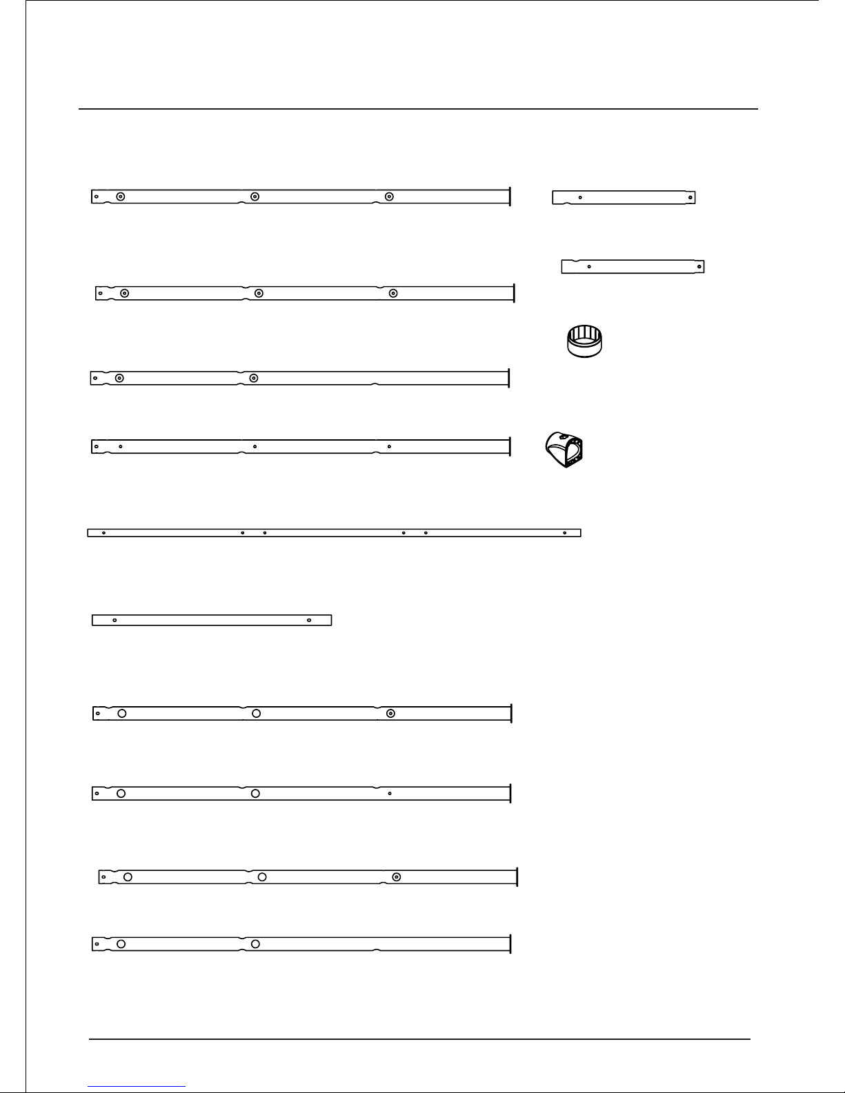
ASSEMBLY PART IDENTIFICATION CHART
7
Before beginning assembly, refer to the drawings below to identify all the parts used in assembly. The
number in parentheses by each drawing is the key number of the part, from the PART LIST on page 18.
Corner Upright
1 (
1) - 2
Side Upright
1 (
2) - 2
Side Upright
2 (
3) - 2
Corner Upright
2 (
4) - 2
Long Cross Bar (5) - 16
Short Cross Bar (6) - 18
Side Upright
3 (
7) - 2
Side Upright
4 (
8) - 2
Middle Upright1 (9) - 2
Middle Upright2 (10) - 2
Top Upright1 (11) - 2
Top Upright2 (12) - 2
Plastic Cap (13) - 16
Plastic Protector (14 ) - 132
Page 8

PRE-ASSEMBLED PART CHART
8
Before beginning assembly, refer to the drawings below to identify all the pre-assembled parts.
Corner Upright
1assembly (
1,13) - 2
Side Upright
1assembly (
2,13) - 2
Side Upright
2 assembly (
3,13) - 2
Corner Upright
2 assembly (
4,13) - 2
Side Upright
3 assembly (
7,13) - 2
Side Upright
4 assembly (
8,13) - 2
Top Upright1
assembly (
11,13) - 2
Top Upright2
assembly (
12,13) - 2
Page 9

9
Make Things Easier for Yourself!
This manual is designed to ensure that the jungle gym can be assemble successfully by anyone
Most people find that by setting aside plenty of time, assembly will go smoothly.
Before beginning assembly
, carefully read the following information and instruction:
*
The assembly requires two persons.
* For help indentifying parts, use the PART IDENTIFICATION CHART on page 7, PREASSEMB LED PART CHART on page 8, and the PART LIST on page 18 and EXPLODED DRAWING
on page 19.
* Place all parts in a cleared area and remove all packaging materials. Do not dispose of the
packaging materials until assembly is completed.
* Tighten all parts as you assemble them, unless instructed to do otherwise.
ASSEMBLY
1
7
15
15
14
14
17
17
16
16
13
13
18
18
19
19
6
1
the first hole
the second hole
the third hole
1. First find the the Corner Upright 1(1) and
Side Upright 3 (7) with marked 1, 7.
Attached two Plastic Protectors (14) to the Short
Cross Bar (6) with two M6X40mm Button Bolts
(16), two M6 Washers (17) and two M6
Locknuts (15).
Then fix Corner Upright 1(1) and Side Upright 3
(7) with two M8 Arc Washers (18) and two M8
X35mm Button Washers (19).
Finally press two Plastic Caps (13) into the
Corner Upright 1(1) and Side Upright 3 (7)
Do not tighten the locknuts.
Page 10

2
2. Attach three Plastic Protectors (14) to the
Long Cross Bar (5) with three M6X40mm Button
Bolts (16), three M6 Washers (17) and three M6
Locknuts (15).
Then fix the Corner Upright (1) with the M8 Arc
Washer (18) and the M8X35mm Button Bolt (19).
Attach the other three Plastic Protectors (14) to
the Long Cross Bar (5) in the same way. And fix
the Corner Upright (1) in the same way.
Do not tighten the locknuts.
14
14
14
14
14
15
15
15
15
15
17
17
17
17
17
16
16
16
16
16
18
19
13
5
5
6
8
16
16
16
17
17
14
14
15
15
15
14
17
18
19
5
5
14
14
1
7
14
3
3. First find the Side Upright 4 (8) with marked 8.
Attach five Plastic Protectors (14) to the Long
Cross Bar (5) and Short Cross Bar (6) with five
M6X40mm Button Bolt (16), five M8 Washers
(17) and five M6 Locknuts (15).
Then fix the Side Upright 4 (8) with the M8 Arc
Washer (18) and the M8X33mm Button Bolt
(19).
Finally press the Plastic Cap (13) to the Side
Upright 4 (8).
Do not tighten the locknuts.
10
Page 11

13
16
17
14
15
5
18
19
16
17
14
15
5
18
19
16
17
14
15
6
18
19
4
4
4. First find the Corner Upright 2 (4) with marked 4.
Attach three Plastic Protectos (14) to two Long
Cross Bars (5) and the Short Cross Bars (6) with
three M6X40mm Button Bolts (16), three M6
Washers (17) and three M6 Locknuts (15).
Finally fix Corner Upright 2 (4) with three M8 Arc
Washers (18) and the Short Cross Bar (6) three
M8X35mm Bolts (19).
Finally press the Plastic Cap (13) to the Corner
Upright 2 (4).
Do not tighten the locknuts.
6
6
6
6
16
17
14
15
18
19
14
14
14
4
8
7
1
5
11
Repeat step 1 to step 5.
5. Attach the Plastic Protectos(14) to the Short
Cross Bars (6) with the M6X40mm Button Bolts
(16), the M6 Washers(17) and the M6 Locknuts
(15). Then fix the Corner Upright 1 (1) with the M8
Arc Washers (18) and the M8X33mm Button Bolts
(19).
Then fix the Side Upright 3 (7), the Side pright 4 (8)
and the Corner Upright 2 (4) in the same way.
Do not tighten the locknuts.
Page 12

2
9
15
15
14
14
16
16
17
17
13
18
18
19
19
6
6. First find the Side Uproght 1(2) and the
Middle Upright 1 (9) with marked 2,9.
Attach two Plastic Protectors (14) to the
Short Cross Bar (6) with two M6 X40mm
Button Bolts (16), two M6 Washers (17) and
two M6 Locknuts (15).
Then fix the Side Uproght 1(2) and the Middle
Upright 1 (9) with two M8 Arc Washers (18)
and two M8X35mm Button Bolts (19).
Finally press the Plastic Caps (13) into the
Side Upright 1 (2).
Do not tighten the locknuts.
6
16
16
16
17
17
14
14
15
15
15
14
17
18
19
5
5
14
14
2
10
14
12
7. Attach three Plastic Protectors (14) to the
Long Cross Bar (5) with three M6X40mm
Button Bolts (16), three M6 Washers(17) and
three M6 Locknuts (15).
Then fix the Side Upright 1 (2) with the M8
Arc Washer (18) and the M8X35mm Button
Bolt (19).
Attach the other three Plastic Protectors (14)
to the Long Cross Bar (5) in the same way.
Then fix the Side Upright 1 (2) in the same
way.
Do not tighten the locknuts.
Page 13

14
14
14
14
15
15
15
15
17
17
17
17
16
16
16
5
5
10
8. First find Middel Upright 2(10) with marked 10.
Attach four Plastic Protectors (14) with four M6
X40mm Button Bolts (16), four M6 Washers
(17) and four four M6 Locknuts (15).
Do not tighten the locknuts.
8
9. First find the Side Upright 2 (3)with marked 3.
Attach two Plastic Protectos(14) to two Long
Cross Bars (5) with two M6X40mm Button
Bolts (16), two M6 Washers (17) and two M6
Locknuts (15).
Then fix the Side Upright 2 (3) with two M8 Arc
Washers (18) and two M8X35mm Button Bolts
(19).
Finally press the Plastic Cap (13) into Side
Upright 2 (3).
Do not tighten the locknuts.
13
16
17
14
15
5
18
19
16
17
14
15
5
18
19
3
9
13
Page 14

13
13
15
14
16
17
18
19
6
15
14
16
17
18
19
11
12
10
10. First find the Top Upright 1 (11), the Top
Upright 2 (12) with marked 11,12.
Attach two Plastic Protectors(14) to the Short
Cross Bar (6) with two M6X40mm Button
Bolts (16), two M6 Washers (17) and two M6
Locknuts (15).
Then fix the Top Upright 1 (11), the Top
Upright 2 (12) with two M8 Arc Washers (18)
and two M8X35mm Button Bolts (19).
Finally press two Plastic Caps (13) into the
Top Upright 1 (11), the Top Upright 2 (12)
Do not tighten the locknuts.
11
12
9
10
20
20
20
20
18
18
18
18
11
11. Attach the Step 9 to the Step 10 with eight M8
Arc Washers (18) and eight M8X20mm Button
Bolts (20).
Do not tighten the locknuts.
Repeat the step 6 step 11.
14
Step 9
Step 10
Page 15

18
19
18
19
18
19
18
19
16
17
14
15
16
17
14
15
16
17
14
15
16
17
14
15
6
6
6
6
2
9
10
3
Step 11 Step 5
12. First find the finished pre-assembled Step 11
as shown.
Attach four Plastic Protectors (14) to four
Short Cross Bars (6) of the Step 5 with four
M6X40mm Button Bolts (16), four M6
Washers(17) and four M6 Locknuts (15).
Fianlly fix the setp 11 with four M8 Arc
Washers (18) and four M8X35mm Button
Bolts (19).
Do not tighten the locknuts.
12
18
19
15
14
17
16
18
19
16
17
14
15
16
17
14
15
5
5
5
5
5
5
5
6
6
5
11
12
1
7
8
2
9
10
3
13.Attach two Plastic Protectors (14) to two
Short Cross Bars (6) with two M6X40mm
Button Bolts (16), two M6 Washers(17)
and two M6 Locknuts (15) .
Then Fix Top Upright 1 (11) and Top Upright
2 (12) with two M8 Arc Washers (18) and two
M8X35mm Button Bolts (19).
Then attach three Plastic Protectors (14) to
the Long Cross bars (5) with three M6X40
mm Button Bolts (16), three M6 Washers(17)
and three M6 Locknuts (15).
Attach the other twenty-one Plastic Protectors
(14) to the other seven Long Cross bars (5) in
the same way.
Fianlly fix the Step 5 with two M8 Arc
Washers (18) and two M8X35mm Button
Bolts (19).
Do not tighten the locknuts.
13
15
Step 5
Step 11
Page 16

2
9
10
3
6
6
5
5
5
5
5
5
5
5
18
19
15
15
15
14
14
14
17
17
16
16
17
16
14. First find the finished pre-assembled Setp 11
as shown.
Attac sixteen Plastic Protectors (14) to eight
Long Cross Bars (5) with sixteen M6X40mm
Button Bolts (16), sixteen M6 Washers(17)
and sixteen M6 Locknuts (15).
Attach two Plastic Protectors (14) to two Short
Cross Bars(6) with two M6X40mm Button Bolts
(16), two M6 Washers(17) and two M6
Locknuts (15).
Then fix the Top Upright 1 (11) of the Step 11
and the Top Upright2 (12) with two M8 Arc
Washers (18) and two M8X35mm Button Bolts
(19).
Do not tighten the locknuts.
14
4
8
7
1
2
9
10
3
5
5
5
5
5
5
5
5
6
6
6
6
18
19
16
17
14
15
18
19
15
14
17
16
15. First find the finished pre-assembled Step 5 as
shown.
Attach eight Plastic Protectors (14) to eight
Long Cross Bars (5) with eight M6X40mm
Button Bolts (16), eight M6 Washers(17) and
eight M6 Locknuts (15).
Then attach four Plastic Protectors (14) to four
Short Cross Bars (6) with four M6X40mm
Button Bolts (16), four M6 Washers(17) and
four M6 Locknuts (15)
Finally fix the Setp 5 and Step 11 with twelve
M8 Arc Washers (18) and twelve M8X35mm
Button Bolts (19).
See step 1 to step 15, tighten all the Button
Bolts (19) and Locknuts (15).
16
Setp 5
11
12
Step 11
Step 11
Page 17

17
! WARNING
Read the assembly, installation, care, maintenance, and use instructions in this manual
prior to assembling and using this Jungle Gym. Save this manual for future reference.
Page 18

PART LIST
1
2
3
4
5
6
7
8
9
10
11
2
2
2
2
16
18
2
2
2
2
2
Key No. Qty Descriprition
Corner Upright 1
Side Upright1
Side Upright
2
Corner Upright
2
Long Cross Bar
Short Cross Bar
Side Upright
3
12
13
14
15
16
17
18
*
*
*
2
16
132
132
132
132
84
-
-
-
Key No. Qty Descriprition
4mm Hex key
5mm
Hex key
Use r’s Manual
18
19
20
68
16
Side Upright
4
Middle Upright1
Middle Upright2
Top Upright1
Top Upright2
Plastic Cap
Plastic Protector
M6 Locknut
M6 Washer
M6 x 40mm Button Bolt
M8 Arc Washer
M8 x 35mm Button Bolt
M8 x 20mm Button Bolt
M6 Locknut (15)
M6 Washer (16)
M6X40mm Button Bolt (17)
M8 Arc Washer(18) M8 x 35mm Button Bolt(19)
M8 x 20mm Button Bolt (20)
4mm Hex key (*)
5mm Hex key (*)
Wrench (*)
Page 19

11
11
12
12
5
6
1
1
4
4
2
2
3
3
7
8
7
8
3
9
10
10
9
14
14
14
14
15
15
15
15
17
16
16
17
16
17
16
17
18
19
18
19
18
19
18
20
20
13
AWING
19
Page 20

MAINTENANCE INFORMATION
This product was manufactured using quality materials and crafted to provide you and your
family with many years of enjoyment and exercise. Proper maintenance care will help to
prolong the life and reduce the possibility of injury. The following guidelines should be followed.
1. Tighten all hardware at the beginning of each play season.
2. Lubricate all metallic moving parts per manufacturer’s instructions.
3. Check all protective coverings on bolts, pipes, edges, and corners. Replace if they
are loose, cracked, or missing.
4. Check all moving parts including swing seats, ropes, cables and chains for wear, rust,
or other deterioration. Replace as needed.
5. Check metal parts for rust. If found, sand and repaint using a nonlead-based paint.
6. Check all wood members for deterioration and splinters. Sand down splinters and
replace deteriorating wood members.
7. Reinstall any plastic parts, such as swing seats or any other items that were removed
for the cold reason.
8. Rake and check depth of loose fill protective surfacing materials to prevent compaction
and to maintain appropriate depth. Replace as necessary.
9. Twice a month during play season: Tighten all hardware, check all protective coverings on
bolts, pipes, edges, and corners. Replace if they are loose, cracked, or missing.
Rake and check depth of loose fill protective surfacing materials to prevent compactionand
to maintain appropriate depth. Replace as necessary.
10. Once a month during play season: Lubricate all metallic moving parts per manufacturer’s
instructionst. Check all moving parts including swing seats, ropes, cables, and chains for
wear, rust, or other deterioration. Replace as needed.
11. At the end of each play season or when the temperature drops below 32°F: remove plastic
swing seats and other items as specified by the manufacturer and take indoors or do not use.
Rake and check depth of loose fill protective surfacing materials to prevent compaction and to
maintain appropriate depth. Replace as necessary. Owners shall be responsible for
maintaining the legibility of the warning labels.
12. Disposal Instructions — Disassemble and dispose of the playground equipment in such a
way that no unreasonable hazards will exist at the time the playground equipment is discarded.
If any these conditions exist, this product should be disassembled or otherwise protected
from being used until the condition is fixed.
20
Page 21

21
LIMITED WARRANTY
Skywalker Holdings, LLC warranties its trampoline products to be free from defects in material and
workmanship under normal use and service conditions. The steel frame is warranted for one (1)
year after the date of purchase. All other parts are warranted for ninety (90) days after the date of
purchase. Wind or weather damage is not warranted.
All warranty coverage extends only to the original retail purchaser from the date of purchase. Skywalker Holdings, LLC obligation under this Warranty is limited to replacing or repairing, at Skywalker
Holdings, LLC option, the product at one of this authorized service centers. All products for which a
warranty claim is made must be received by Skywalker Holdings, LLC at one of its authorized
locations. Preauthorization may be obtained by calling Skywalker Holding, LLC Customer Care Hot
Line at 1-866-603-Jump(5867). This Warranty does not extend to any product or damage to a
product caused by or attributable to freight damage, abuse, misuse, improper or abnormal usage, or
repair not provided by a Skywalker Holdings, LLC authorized service center, or to products used for
commercial or rental purpose. No other Warranty beyond that specifically set forth above is authorized by Skywalker Holdings, LLC.
SKYWALKER HOLDINGS, LLC IS NOT RESPONSIBLE OR LIABLE FOR INDIRECT, SPECIAL
OR
CONSEQUENTIAL DAMAGES ARISING OUT OF OR IN CONNECTION WITH THE USE OR
PERFORMANCE OF THE PRODUCT OR OTHER DAMAGES WITH RESPECT TO ANY ECONOMIC LOSS, LOSS OF PROPERTY, LOSS OF REVENUE OR PROFITS, LOSS OF ENJOYMENT OR USE, COST OF REMOVAL, INSTALLATION OR OTHER CONSEQUENTIAL DAMAGES. SOME STATES DO NOT ALLOW THE EXCLUSION OR LIMITATION OF INCIDENTAL OR
CONSEQUENTIAL DAMAGES. ACCORDINGLY, THE ABOVE LIMITATION MAY NOT APPLY TO
YOU.
THE WARRANTY EXTENDED HEREUNDER IS IN LIEU OF ALL OTHER WARRANTIES AND ANY
IMPLIED WARRANTY OF MERCHANTABILITY OR FITNESS FOR A PARTICULAR PURPOSE IS
LIMITED IN ITS SCOPE AND DURATION TO THE TERMS SET FORTH HEREIN. SOME STATES
DO NOT ALLOW LIMITATIONS ON HOW LONG AN IMPLIED WARRANTY LASTS. ACCORDINGLY, THE ABOVE
LIMITATION MAY NOT APPLY TO YOU. This Warranty gives you specific LEGAL RIGHTS. You
may also have other rights which vary state to state.
THIS WARRANTY IS VALID ONLY IN THE UNITED STATES.
Skywalker Holdings, LLC, PO Box 574, Brigham City, UT 84302 USA.
Printed in China © 2014 Skywalker Holdings, LLC,
 Loading...