

skyvoe NXG-4270-DS, NXG-3250-DS, NXG-7070-DS, NXG-4250-DS, NXG-5550-DS Owner's Manual
...
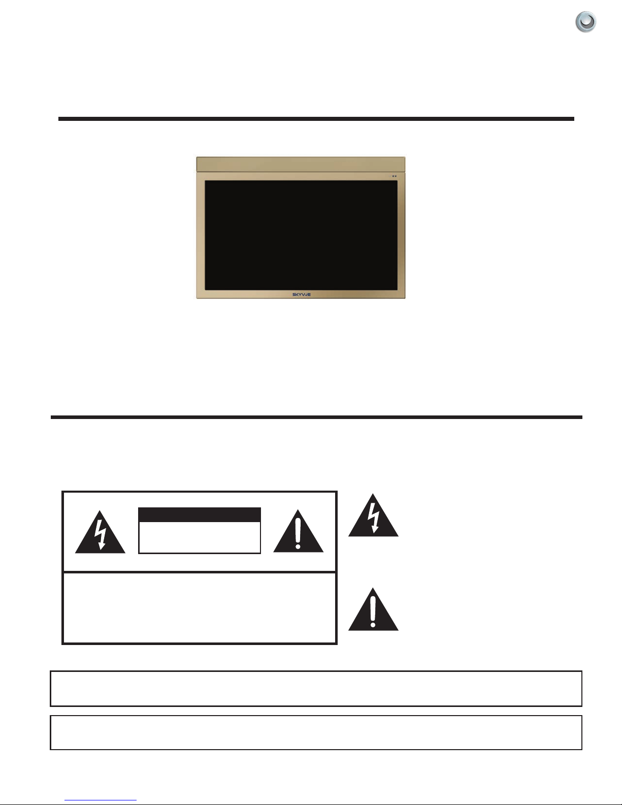
NXG-3250MODEL:
Owner’s Manual
Weatherproof Televisions
IMPORTANT:
Please read this owners manual before
starting or operating the equipment.


Dear SkyVue Customer,
Congratulations on purchasing your new outdoor weather-proof television. We welcome you to our
SkyVue family. To gain the full potential of your new SkyVue Outdoor Television, please read carefully the
instructions within this document. There is a wealth of relevant information to get started and fully utilize all
of the unique capabilities of your new SkyVue Outdoor Television. We sincerely thank you for your purchase
and hope you have several years of enjoyment from your new SkyVue Outdoor Television.
We at SkyVue have taken a studied approach to delivering the highest quality and reliable outdoor
television on the market. SkyVue started with the goals of operating with unparalleled customer service
and extensive research and development. Upon extensive research of national competition, we realized that
yet, all outdoor television manufacturers purchase the circuitry and panels in their products overseas; that
SkyVue is the only manufacturer that completes its designs with all American Made products. Our family
of televisions are re-innovating the ideas, functions, and technologies, in which other outdoor television
manufacturers seemed to have missed. We take pride in every product and are glad to have you as part of
our family.
Customer Service can be directly reached at:
1-(877) 4-SkyVue
1-(877) 475-9883
CustomerService@SkyVue.com
To inquire about extended warranty information, accessories, or installation FAQs please visit our website
www.skyvue.com.
We Thank You for Your Support,
The SkyVue Management Team

Model :
OPERATION MANUAL
LED TELEVISION
ENGLISH
SKY4230 & SKY4630
NXG-3250
NexGen - SERIES OUTDOOR LED TELEVISION
IMPORTANT:
To aid reporting in case of loss or theft, please record the
TV's model and serial numbers in the space provided. The
numbers are located at the rear of the TV.
OWNER’S MANUAL
IMPORTANT INFORMATION
CAUTION
RISK OF ELECTRIC SHOCK
DO NOT OPEN
CAUTION: TO REDUCE THE RISK OF ELECTRIC SHOCK,
CAUTION:
DO NOT REMOVE COVER (OR BACK).
NO USER-SERVICEABLE PARTS INSIDE.
REFER SERVICING TO QUALIFIED SERVICE
PERSONNEL.
TO PREVENT ELECTRIC SHOCK, MATCH WIDE BLADE OF PLUG TO WIDE
SLOT, FULLY INSERT.
The lightning flash with arrow-head
symbol, within an equilateral triangle,
is intended to alert the user to the
presence of uninsulated “dangerous
voltage” within the product's
enclosure that may be of sufficient
magnitude to constitute a risk of
electric shock to persons.
The exclamation point within a
triangle is intended to alert the user
to the presence of important
operating and maintenance
(servicing) instructions in the
literature accompanying the product.
WARNING: FCC Regulations state that any unauthorized changes or modifications to this equipment not expressly
approved by the manufacturer could void the user's authority to operate this equipment.
3Owner’s Manual - Model NXG-3250 Imp orta nt Inf orm atIon |
CAUTION:
IMPORTANT INFORMATION
This product satisfies FCC regulations when shielded cables and connectors are used to connect the unit to other
equipment. To prevent electromagnetic interference with electric appliances such as radios and televisions, use shielded
cables and connectors for connections.
DECLARATION OF CONFORMITY:
SK Y4220 & SK Y4630
Model No.: NXG-3250
This device complies with Part 15 of the FCC Rules. Operation is subject to the following two conditions:
(1) This device may not cause harmful interference, and (2) this device must accept any interference
received, including interference that may cause undesired operation.
RESPONSIBLE PARTY:
1439 Dave Lyle Blvd Unit 15 Rock Hill, SC 29730
Visit us online at www.skyvue.com
Skyvue Television
TEL: 1-877-475-9883
INFORMATION:
This equipment has been tested and found to comply with the limits for a Class B digital device, pursuant to Part 15 of the FCC
Rules. These limits are designed to provide reasonable protection against harmful interference in a residential installation. This
equipment generates, uses and can radiate radio frequency energy and, if not installed and used in accordance with the
instructions, may cause harmful interference to radio communications. However, there is no guarantee that interference will not
occur in a particular installation. If this equipment does cause harmful interference to radio or television reception, which can be
determined by turning the equipment off and on, the user is encouraged to try to correct the interference by one or more of the
following measures:
Reorient or relocate the receiving antenna.
Increase the separation between the equipment and receiver.
Connect the equipment into an outlet on a circuit different from that to which the receiver is connected.
Consult the dealer or an experienced radio/TV technician for help.
FCC Compliance Statement
This device complies with part 15 of the FCC Rules. Operation is subject to the following two conditions:
(1) This device may not cause harmful interference, and (2) this device must accept any interference received, including
interference that may cause undesired operation.
Wireless Radio
For product available in the USA/Canada market, only channel 1–11 can be operated. Selection of other channels is not possible.
This device is going to be operated in 5.15–5.25GHz frequency range, it is restricted in indoor environment only.
Important: Any changes or modifications not expressly approved by the party responsible for compliance could void the user’s
authority to operate the equipment.
FCC Radiation Exposure Statement: This equipment complies with FCC radiation exposure limits set forth for an uncontrolled
environment. This equipment should be installed and operated with minimum distance 20cm between the radiator & your body.
Industry Canada Statement
This Class B digital apparatus complies with Canadian ICES-003.
Cet appareil numérique de la classe B est conforme à la norme NMB-003 du Canada.
Operation is subject to the following two conditions:
(1) This device may not cause harmful interference, and (2) this device must accept any interference received, including
interference that may cause undesired operation of the device. This device and its antenna(s) must not be colocated or
operation in conjunction with any other antenna or transmitter.
Wireless Radio
For product available in the USA/Canada market, only channel 1–11 can be operated. Selection of other channels is not possible.
The device could automatically discontinue transmission in case of absence of information to transmit, or operational failure.
Note that this is not intended to prohibit transmission of control or signaling information or the use of repetitive codes where
required by the technology.
Important: Any changes or modifications not expressly approved by the party responsible for compliance could void the user’s
authority to operate the equipment.
IC Radiation Exposure Statement: This equipment complies with IC RSS-102 radiation exposure limits set forth for an
uncontrolled environment. This equipment should be installed and operated with minimum distance 20 cm between the radiator
& your body.
“Note to CATV system installer: This reminder is provided to call the CATV system installer's attention to Article 820 of the National
Electrical Code that provides guidelines for proper grounding and, in particular, specifies that the cable ground shall be connected to the
grounding system of the building, as close to the point of cable entry as practical.”
4 All Rights Reserved. 2014 SkyVue
®

Electricity is used to perform many useful functions, but it can also cause personal injuries and property damage
if improperly handled. This product has been engineered and manufactured with the highest priority on safety.
However, improper use can result in electric shock and/or fire. In order to prevent potential danger, please
observe the following instructions when installing, operating and cleaning the product. To ensure your safety
and prolong the service life of your LED Television, please read the following precautions carefully
before using the product.
1) Read these instructions.
2) Keep these instructions.
3) Heed all warnings.
4) Follow all instructions.
5) Clean only with dry cloth.
6) Do not block any ventilation openings. Install in accordance with the manufacturer's instructions.
7) Do not install near any heat sources such as radiators, heat registers, stoves, or other apparatus (including
amplifiers) that produce heat.
8) Do not defeat the safety purpose of the polarized or grounding-type plug. A polarized plug has two blades
with one wider than the other. A grounding type plug has two blades and a third grounding prong. The
wide blade or the third prong are provided for your safety. If the provided plug does not fit into your outlet,
consult an electrician for replacement of the obsolete outlet.
09) Protect the power cord from being walked on or pinched particularly at plugs, convenience receptacles,
and the point where they exit from the apparatus.
10) Only use attachments/accessories specified by the manufacturer.
11) Use only with the cart, stand, tripod, bracket, or table specified by the manufacturer, or sold
with the apparatus. When a cart is used, use caution when moving the cart/apparatus
combination to avoid injury from tip-over.
12) Unplug this apparatus during lightning storms or when unused for long periods of time.
13) Refer all servicing to qualified service personnel. Servicing is required when the apparatus has been
damaged in any way, such as power-supply cord or plug is damaged, does not operate normally, or has
been dropped.
Additional Safety Information
14) Power Sources—This product should be operated only from the type of power source indicated on the
marking label. If you are not sure of the type of power supply to your home, consult your product dealer or
local power company. For products intended to operate from battery power, or other sources, refer to the
operating instructions.
15) Overloading—Do not overload wall outlets, extension cords, or integral convenience receptacles as this
can result in a risk of fire or electric shock.
16) Damage Requiring Service—Unplug this product from the wall outlet and refer servicing to qualified
service personnel under the following conditions:
a) When the AC cord or plug is damaged,
b) If the product does not operate normally by following the operating instructions.
Adjust only those controls that are covered by the operating instructions as an improper adjustment
of other controls may result in damage and will often require extensive work by a qualified technician
to restore the product to its normal operation,
c) If the product has been dropped or damaged in any way, and
d) When the product exhibits a distinct change in performance - this indicates a need for service.
17) Replacement Parts—When replacement parts are required, be sure the service technician has used
replacement parts specified by the manufacturer or have the same characteristics as the original part.
Unauthorized substitutions may result in fire, electric shock, or other hazards.
18) Safety Check—Upon completion of any service or repairs to this product, ask the service technician to
perform safety checks to determine that the product is in proper operating condition.
19) Wall or ceiling mounting—When mounting the product on a wall or ceiling, be sure to install the product
according to the method recommended by the manufacturer.
5Owner’s Manual - Model NXG-3250 Imp orta nt Inf orm atIon |
IMPORTANT SAFETY INSTRUCTIONS
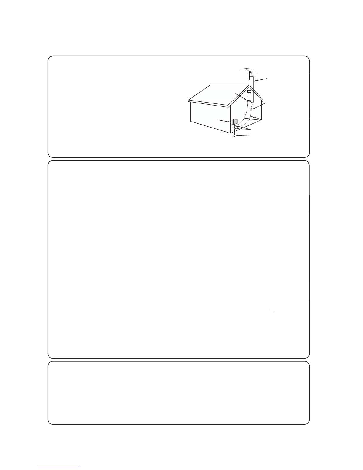
• Outdoor Antenna Grounding — If an outside antenna is
• Outdoor Antenna Grounding — If an outside antenna is
EXAMPLE OF ANTENNA GROUNDING AS PER
NATIONAL ELECTRICAL CODE, ANSI/NFPA 70
ANTENNA
LEAD IN WIRE
GROUND
CLAMP
ELECTRIC
ANTENNA
DISCHARGE UNIT
(NEC SECTION 810-20)
connected to the television equipment, be sure the antenna
EXAMPLE OF ANTENNA GROUNDING AS PER
NATIONAL ELECTRICAL CODE, ANSI/NFPA 70
system is grounded so as to provide some protection against
voltage surges and built-up static charges.
Article 810 of the National Electrical Code, ANSI/NFPA 70,
connected to the television equipment, be sure the antenna
provides information with regard to proper grounding of the
system is grounded so as to provide some protection against
mast and supporting structure, grounding of the lead-in wire
voltage surges and built-up static charges.
to an antenna discharge unit, size of grounding conductors,
Article 810 of the National Electrical Code, ANSI/NFPA 70,
location of antenna-discharge unit, connection to grounding
provides information with regard to proper grounding of the
electrodes, and requirements for the grounding electrode.
mast and supporting structure, grounding of the lead-in wire
to an antenna discharge unit, size of grounding conductors,
ELECTRIC
SERVICE
EQUIPMENT
GROUND
CLAMP
location of antenna-discharge unit, connection to grounding
electrodes, and requirements for the grounding electrode.
NEC — NATIONAL ELECTRICAL CODE
• Stand — Do not place the product on an unstable cart, stand, tripod or table. Placing the product
on an unstable base can cause the product to fall, resulting in serious personal injuries as well as
damage to the product. Use only a cart, stand, tripod, bracket or table recommended by the
manufacturer or sold with the product. When mounting the product on a wall, be sure to follow
the manufacturer's instructions. Use only the mounting hardware recommended by the manufacturer.
• Ventilation — The vents and other openings in the cabinet are designed for ventilation. Do not cover or block these vents
and openings since insuffi cient ventilation can cause overheating and/or shorten the life of the product. Do not place
the product on a bed, sofa, rug or other similar surface, since they can block ventilation openings. This product is not
designed for built-in installation; do not place the product in an enclosed place such as a bookcase or rack, unless proper
ventilation is provided or the manufacturer's instructions are followed.
• The front panel used in this product is made of glass. Therefore, it can break when the product is dropped or applied with
impact. Be careful not to be injured by broken glass pieces in case the panel breaks.
• Heat — The product should be situated away from heat sources such as radiators, heat registers, stoves, or other
products (including amplifi ers) that produce heat.
• The LED panel is a very high technology product with 2,073,600 pixels, giving you fi ne picture details.
Occasionally, a few non-active pixels may appear on the screen as a fi xed point of blue, green or red
blue, green, red or yellow. Please note that this does not affect the performance of your product.
• Lightning — For added protection for this television equipment during a lightning storm, or when it is left unattended and
unused for long periods of time, unplug it from the wall outlet and disconnect the antenna. This will prevent damage to
the equipment due to lightning and power-line surges.
• Power Lines — An outside antenna system should not be located i
n the vicinity of overhead power lines or other electric
light or power circuits, or where it can fall into such power lines or circuits. When installing an outside antenna system,
extreme care should be taken to keep from touching such power lines or circuits as contact with them might be fatal.
• To prevent fi re, never place any type of candle or fl ames on the top or near the TV set.
• To prevent fi re or shock hazard, do not place the AC cord under the TV set or other heavy items.
• Do not display a still picture for a long time, as this could c
ause an afterimage to remain.
• Do not insert foreign objects into the product. Inserting objects in the air vents or other openings may
result in fi re or electric shock. Exercise special caution when using the product around children.
ANTENNA
LEAD IN WIRE
ANTENNA
DISCHARGE UNIT
(NEC SECTION 810-20)
GROUNDING
CONDUCTORS
(NEC SECTION 810-21)
GROUND CLAMPS
POWER SERVICE GROUNDING
ELECTRODE SYSTEM
(NEC ART 250)
Precautions when transporting the TV
• When transporting the TV, never carry it by holding or otherwise putting pressure onto the display. Be sure to always
carry the TV by two people holding it with two hands — one hand on each side of the TV.
Caring for the cabinet
• Use a soft cloth (cotton, fl annel, etc.) and gently wipe the surface of the cabinet.
• Using a chemical cloth (wet/dry sheet type cloth, etc.) may deform the components of the main unit cabinet or cause
cracking.
• Wiping with a hard cloth or using strong force may scratch the surface of the cabinet.
• If the cabinet is very dirty, wipe with a soft cloth (cotton, fl annel, etc.) soaked in neutral detergent diluted with water and
thoroughly wrung out, and then wipe with a soft dry cloth.
• Avoid using benzene, thinner, and other solvents, as these may
• Do not apply insecticides or other volatile liquids.
Also, do not allow the cabinet to remain in contact with rubber
inside the plastic may cause the cabinet to deform and cause the paint to peel off.
6 All Rights Reserved. 2014 SkyVue
deform the cabinet and cause the paint to peel off.
or vinyl products for a long period of time. Plasticizers
®
IMPORTANT SAFETY INSTRUCTIONS
Caring for the front panel
• Turn off the main power and unplug the AC cord from the GFI wall outlet before handling.
• Gently wipe the surface of the front panel with a soft cloth (cotton, fl annel, etc.).
To protect the front panel, do not use a dirty cloth, liquid cleaners, or a chemical cloth (wet/dry
sheet type cloth, etc.). This may damage the surface of the front panel.
• Wiping with a hard cloth or using strong force may scratch the surface of the front panel.
• Use a soft damp cloth to gently wipe the front panel when it is really dirty.
(It may scratch the surface of the front panel when wiped strongly.)
• If the front panel is dusty, use an anti-static brush, which is commercially available, to clean it.
• To avoid scratching the frame or screen, please use a soft, lint free cloth for cleaning.
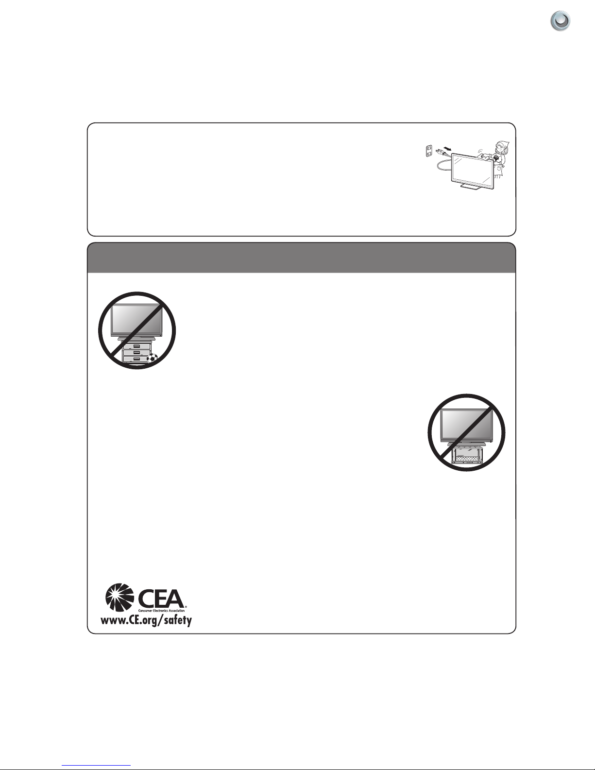
CHILD SAFETY:
It Makes A Difference How and Where You Use Your Flat Panel Display
Congratulations on your purchase! As you enjoy your new product, please keep these safety tips in mind:
THE ISSUE
• The home theater entertainment experience is a growing trend and larger fl at panel displays
are popular purchases. However, fl at panel displays are not always supported on the proper
stands or installed according to the manufacturer’s recommendations.
• Flat panel displays that are inappropriately situated on dressers, bookcases, shelves, desks,
speakers, chests or carts may fall over and cause injury.
THIS MANUFACTURER CARES!
• The consumer electronics industry is committed to making home entertainment enjoyable
and safe.
TUNE INTO SAFETY
• One size does NOT fi t all. Follow the manufacturer’s recommendations for the safe installation
and use of your fl at panel display.
• Carefully read and understand all enclosed instructions for proper use of this product.
• Don’t allow children to climb on or play with furniture and television sets.
• Don’t place fl at panel displays on furniture that can easily be used as steps, such as a chest
of drawers.
• Remember that children can become excited while watching a program, especially on a
“larger than life” fl at panel display. Care should be taken to place or install the display where it
cannot be pushed, pulled over, or knocked down.
• Care should be taken to route all cords and cables connected to the fl at panel display so that
they cannot be pulled or grabbed by curious children.
WALL MOUNTING: IF YOU DECIDE TO WALL MOUNT YOUR FLAT PANEL DISPLAY, ALWAYS:
• Use a mount that has been recommended by the display manufacturer and/or listed by an independent laboratory (such
as UL, CSA, ETL).
• Follow all instructions supplied by the display and wall mount manufacturers.
• If you have any doubts about your ability to safely install your fl at panel display, contact your retailer about professional
installation.
• Make sure that the wall where you are mounting the display is appropriate. Some wall mounts are not designed to be
mounted to walls with steel studs or old cinder block construction. If you are unsure, contact a professional installer.
• A minimum of two people are required for installation. Flat panel displays can be heavy.
Note:
CEA is the preeminent trade association promoting growth in the $161 billion U.S.
consumer electronics industry. More than 2,200 companies enjoy the benefi ts of CEA
membership, including legislative advocacy, market research, technical training and
education, industry promotion and the fostering of business and strategic relationships
.
7Owner’s Manual - Model NXG-3250 Imp orta nt Inf orm atIon |

SkyVue OutdOOr tV Safety InStructIOnS
Ventilation: Adequate ventilation must be maintained to ensure reliable and continued operation and to protect the
television from overheating. There must be at least 1.5” of space on all sides.
Power cord protection: The power cord must be routed properly to prevent people from stepping on it, or objects
from resting on it. Check the cords at the plugs and product.
Power source: This product must operate on a power source specied on the specication label. If you are unsure
of the type of power supply used in your home, consult your dealer or local power company.
Do not let metal pieces or objects of any kind fall into the television from ventilation holes. High voltage ows in
the product, and inserting an object can cause electric shock and/or short internal parts.
Do not mount SkyVue Outdoor TV’s near heat sources such as radiators, heaters, stoves and other heatgenerating products (including ampliers).
Do not submerge SkyVue Outdoor TV’s in water:
The SkyVue Outdoor TV’s will resist water exposure from normal rain, sprinklers, garden hoses, etc.; however, it is
not designed to withstand pressure washers, high-pressure water jets, hurricane-type weather or be submerged in
water.
Repair:
If any of the following conditions occurs, unplug the power cord, and call SkyVue Outdoor TVs Technical Service
Department for repairs:
• When power cord or plug is damaged.
• When objects have fallen into the product.
• If unit was submerged in water or pressure-washed.
• When product does not operate properly as described in the operating instructions. Do not touch the
controls other than as described in the operating instructions. Improper adjustments of controls not
described in the instructions can cause damage, which can require extensive repair work by a qualied
technician.
• When the product has been dropped or damaged.
• When the product displays an abnormal condition. Any noticeable abnormality in the product indicates that
the product needs servicing.
Replacement parts:
In case the product needs replacement parts, make sure that the you or your service person uses replacement parts
provided by SkyVue Outdoor TV. Use of unauthorized parts can result in re, electric shock and/or other danger.
8 All Rights Reserved. 2014 SkyVue
®

Table of Contents
WelcOme ................................................................................................................................ 1
ImpOrtant InfOrmatIOn .......................................................................................................... 3
Safety InfOrmatIOn ............................................................................................................... 4
tV InStallatIOn ................................................................................................................. 10
Choose a LoCation for the tV .......................................................................................... 10
rear PaneL ComPonent sourCe ........................................................................................ 11
rear PaneL ConneCtions .................................................................................................. 12
DetaChabLe sPeakerbar .................................................................................................... 15
manual cOntrOlS On tV .................................................................................................. 24
frOnt panel lIghtS and SenSOrS ...................................................................................... 24
remOte cOntrOl guIde ...................................................................................................... 25
On-Screen dISplay (OSd) functIOnS ............................................................................... 26
On-Screen dISplay menu .................................................................................................. 27
ChanneL menu ................................................................................................................. 27
PiCture menu ................................................................................................................... 27
auDio menu ..................................................................................................................... 27
time menu ....................................................................................................................... 28
setuP menu ..................................................................................................................... 28
LoCk menu ...................................................................................................................... 28
adjuStIng On-Screen dISplayS - channel menu ............................................................ 29
adjuStIng On-Screen dISplayS – pIcture menu ............................................................. 31
adjuStIng On-Screen dISplayS – audIO menu ................................................................. 32
adjuStIng On-Screen dISplayS – tIme menu ................................................................... 34
adjuStIng On-Screen dISplayS – Setup menu ................................................................ 36
adjuStIng On-Screen dISplayS – lOck menu .................................................................. 49
uSIng the uSB Input .......................................................................................................... 43
trOuBleShOOtIng ................................................................................................................. 45
care Of SkyVue OutdOOr tV ............................................................................................ 47
SpecIfIcatIOnS ...................................................................................................................... 48
tV care & pOlIcy InfOrmatIOn ........................................................................................ 49
rS232 cOntrOl cOdeS .................................................................................................... 50
9Owner’s Manual - Model NXG-3250 Tab le of Con Ten Ts |

Unpacking
After unpacking the SkuVue Outdoor TV, please make sure that the following items are included in the carton and
that they are in good condition. If items are damaged or missing, contact your dealer immediately.
Model NXG-3250 Front View
NXG-4250MODEL:
Owner’s Manual
Weatherproof Televisions
IMPORTANT:
Please read this owners manual before
starting or operating the equipment.
Owner’s Manual
TV Installation
Choose a Location for the TV
Important: The TV must be installed at least 5 feet from
pool, spa, or other body of water.
The TV should be installed so the screen is not facing
direct sunlight, or can be easily turned away from direct
sunlight. Ideal placement is in an area where the TV is
shaded by trees, landscape and/or structures, or under
a patio cover or gazebo. Remember that the position of
the sun changes during the day, as seen in the drawing
on the right. This means that the quality of the picture
will change during the day. If you intend to install the
TV in areas where direct sunlight will reach it, it’s best
to position the TV for optimum performance during the
time of day when you do most of your TV watching. If
the sun shines directly on the screen for long periods
of time, dark areas may develop on the screen. This is
a normal reaction for the LED panel, and will not cause
damage to the screen. Either turn the screen away from
the sun, or apply shade to the TV, and the dark areas
will quickly disappear.
Model NXG-3250 Back View
Remote Control
Afternoon
Sunrise Sunset
10 All Rights Reserved. 2014 SkyVue
®
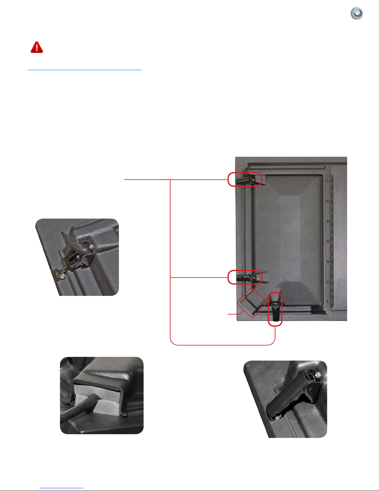
Rear Panel Component Source
WARNING: Do not connect the power source before making connections.
Internal Component Source
The Internal Component Source allows you to easily connect to the Audio, Video, Digital Audio Out, HDMI, Audio
Out, and RF connectors.
1. The Internal Component Source is inside the Component Cover located on the back of the unit.
2. Open the 3 latches located on the back cover of your SkyVue TV , and pull the cover towards you.
3. Route cables to the proper inputs, and place the cable cords over the Rubber Sealing Gasket.
4. Close the cover.
5. Press rmly on the cover, and secure the hinged latches.
Component Cover Latches
OPEN LATCH
CABLE PASSAGE
CABLE PASSAGE
CLOSED LATCH
11Operator’s Manual - Model NXG-3250 TV Ins Tall aTIo n & Co nne CTI ons |
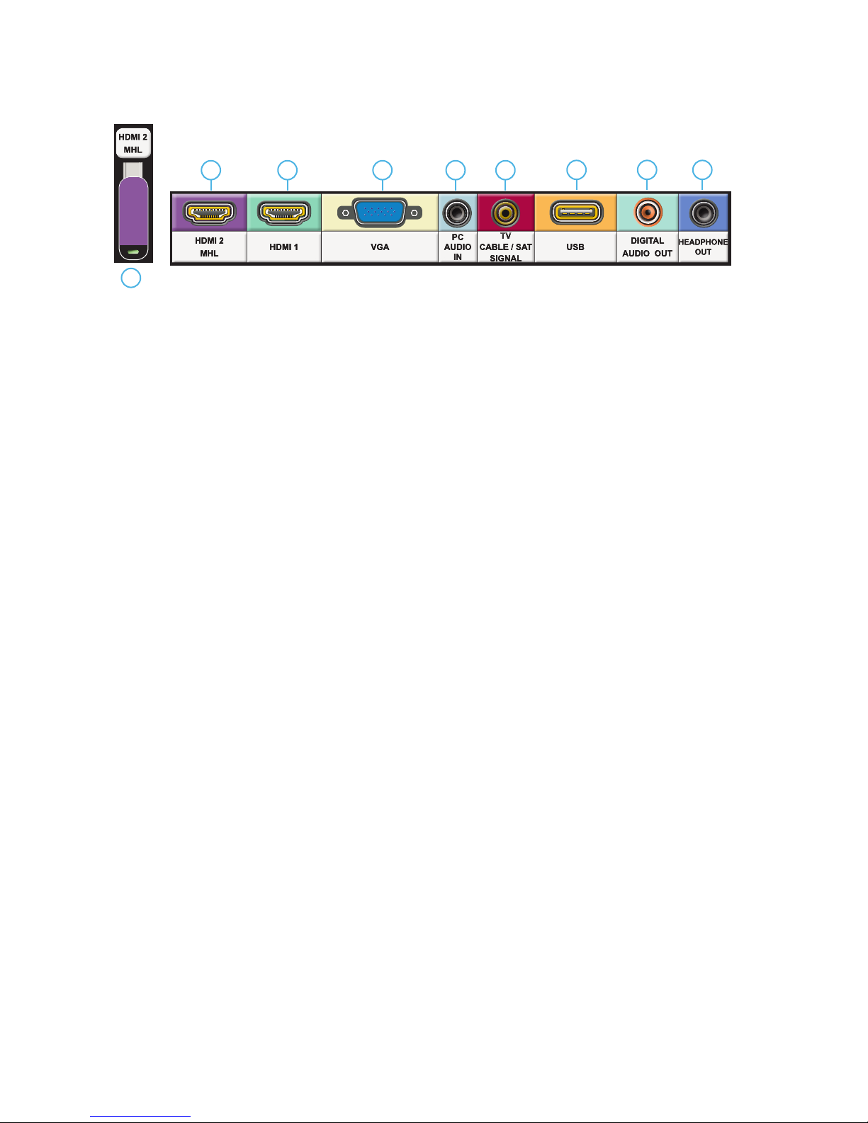
Rear Panel Connections-Horizontal
1
1a
1. HDMI 2 - Use this port for Integrated Internet Streaming Devices
Connects to devices that use HDMI cables such as Blu-ray or HD DVD/Blu-ray player or HD cable / satellite settop box. This connection port receives pure digital audio and high denition signal through one single cable. This
port also can accept a HDCP video device for video or PC for monitor display usage. Use the SOURCE button to
select HDMI2 on your MAIN SOURCE to view this connection.
Please note: when using HDMI, your sound signal must be PCM for the TV to decode digital audio. When using this
source for PC display, you must connect the audio cable to VGA Stereo Input for audio.
1a. HDMI 2 extension
2. HDMI 1 - Same as HDMI 2
Please note: This port does not support MHL devices.
2 3 4 5
6 7 8
HORIZONTAL TERMINAL PORTS
3. VGA - This connection port connects to a PC for video using VGA cable. Be sure to connect your audio cable to
the VGA Stereo input if you want sound out of the VGA video source. Use the SOURCE button to select VGA on
your MAIN SOURCE to view this connection.
4. PC Audio IN - This connection port is for people who want to provide audio to the TV when using a PC or a DVI
video device. Use a 3.5mm mini-jack audio cable (headphone jack) to provide audio for a HDCP enabled DVI
video device or PCs with VGA or DVI connection.
5. ATSC/NTSC – This connection is for digital or analog cable without the cable box or over-the-airwave antennas.
The tuner is a hybrid tuner that tunes to both analog and digital channels. This connection uses coaxial RF cable.
For over- the airwave digital stations please check http://www.antennaweb.org.
6. USB - The USB and high speed serial port allows viewers access to les stored on a USB memory device. See
“Using USB” Sections for further details.
7. Digital Audio Out - This type of jack is used for the digital audio inputs and/or outputs on A/V components such
as receivers, CD players, DVD players, and more. Coaxial digital jacks are also sometimes found on higher-end
PC soundcards for digital audio input and output.
8. Headphones Out - Use a 3.5 mm mini-jack for use with standard headphones.
12 All Rights Reserved. 2014 SkyVue
®

Rear Panel Connections - Vertical
9
RS-232
AV
AUDIO (L)
OUT
SPEAKER BAR
10
AUDIO (R)
AV
OUT
12
Y
SIGNAL
Pb
SIGNAL
IN
IN
COMPONENT COMPOSITE
Pr
SIGNAL
IN
13
AV
IN
AV
AUDIO (L)
IN
AV
AUDIO (R)
IN
1411
VERTICAL TERMINAL PORTS
9. RS-232C - Long established standard connection (“C” is the current version) that describes the physical
interface and protocol for relatively slow data communications between computers and related devices.
10. AV Audio (L/R) Out / SkyVue Speakerbar - AV audio outputs are the standard means of passing analog line-level (or “preamp-level”) audio signals between components. AV or RCA jacks are commonly found on most types of
A/V gear: receivers, CD players, turntables, MiniDisc recorders, cassette decks, VCRs, DVD players, and more.
11. Component Video Jacks -This 3-cable connection allows the chrominance (color) and luminance (brightness)
portions of a video signal to be processed separately. Component video improves color accuracy further by splitting the chrominance signal into two portions.
12. Composite Video In – The composite video input uses a single standard RCA-style jack to pass video signals. This type of connection combines chrominance and luminance information, sending it along a single cable.
Though capable of delivering a high-quality picture, composite video is not as accurate as component video.
13. Composite Audio In - Used in accompanyment with composite Video and component video jacks, AV audio in
(L/R) delivers analog sound from gaming consoles, dvd players, and VCRs.
14. HDMI 3 - Same as HDMI 2
Please note: This port does not support MHL devices.
13Operator’s Manual - Model NXG-3250 TV Ins Tall aTIo n & Co nne CTI ons |
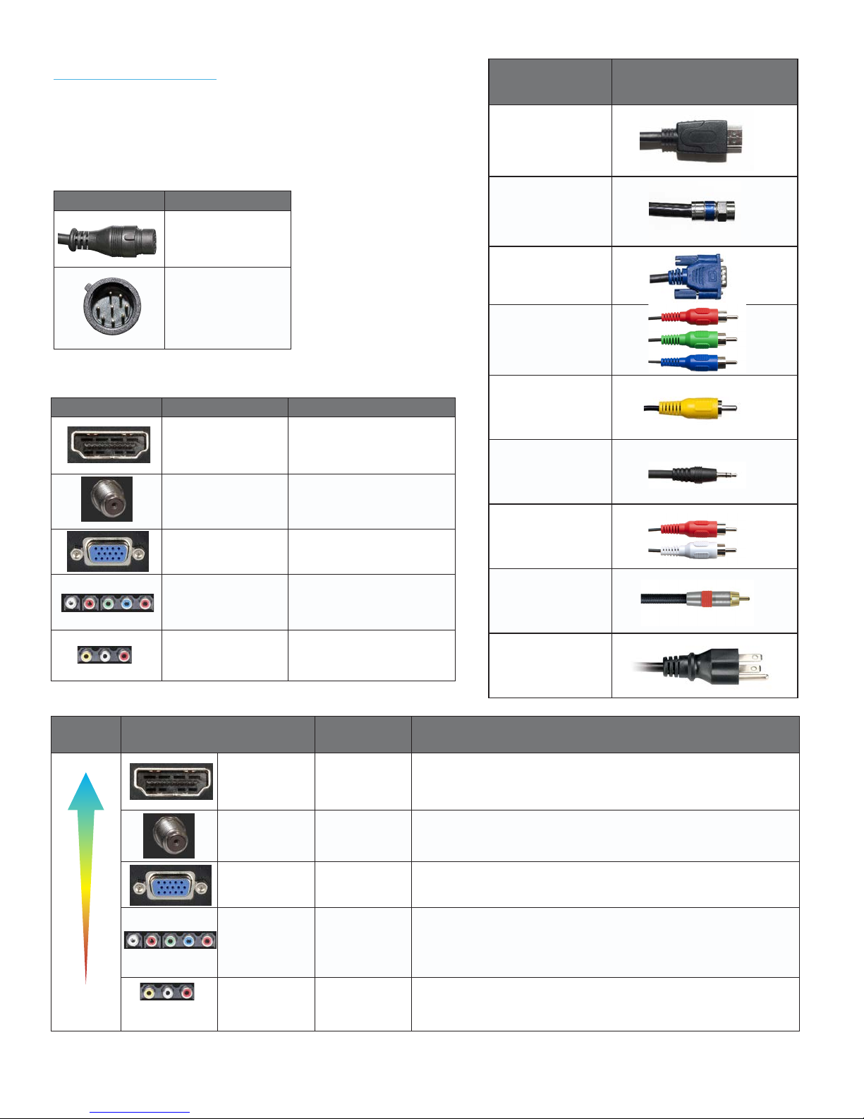
Switching Inputs:
Your SkyVue TV offers several options when connecting your
devices to the TV. The chart below will help you understand
which input you select for each of the connections.
Cable Name Cable End Images
HDMI or HDMI-DVI
Connections Cable Name
Speaker Bar Audio
(Female)
Speaker Bar Audio
(Male)
Connections Cable to Use Input to Select
HDMI OR HDMI-DVI HDMI
COAXIAL RF TV (CABLE/AIR)
VGA
Component
VGA
YPBPR
Coaxial RF
VGA
Component
Composite
3.5 mm Mini-jack
RCA Audio
Coaxial SPDIF
IMAGE
QUALITY
HD IMAGE
STANDARD
IMAGE
Composite AV1
Terminal
Port
HDMI
(Digital HD)
ATSC/NTSC
(Digital HD)
VGA
(HD)
Component
(HD)
Composite
(non-HD)
Resolution Typical Devices Used for This Input
1080i, 720p,
480p, 480i
1080i, 720p,
480p, 480i
1980 x 1080
or lower
1080i, 720p,
480p, 480i
480i Only Non High Definition Cable or Satellite Box, VCR, Older Game Consoles, Camcorder
AC Power
Blue-Ray DVD Player,
HD-DVD Player,
HD Cable or Satellite Box,
HDCP devices
Antenna or Digital Cable (With out cable box)
PC or MAC with VGA Connection
Blue-Ray DVD Player,
HD-DVD Player,
HD Cable or Satellite Box,
HDCP devices,
Skyvue Speakerbar
14 All Rights Reserved. 2014 SkyVue
®
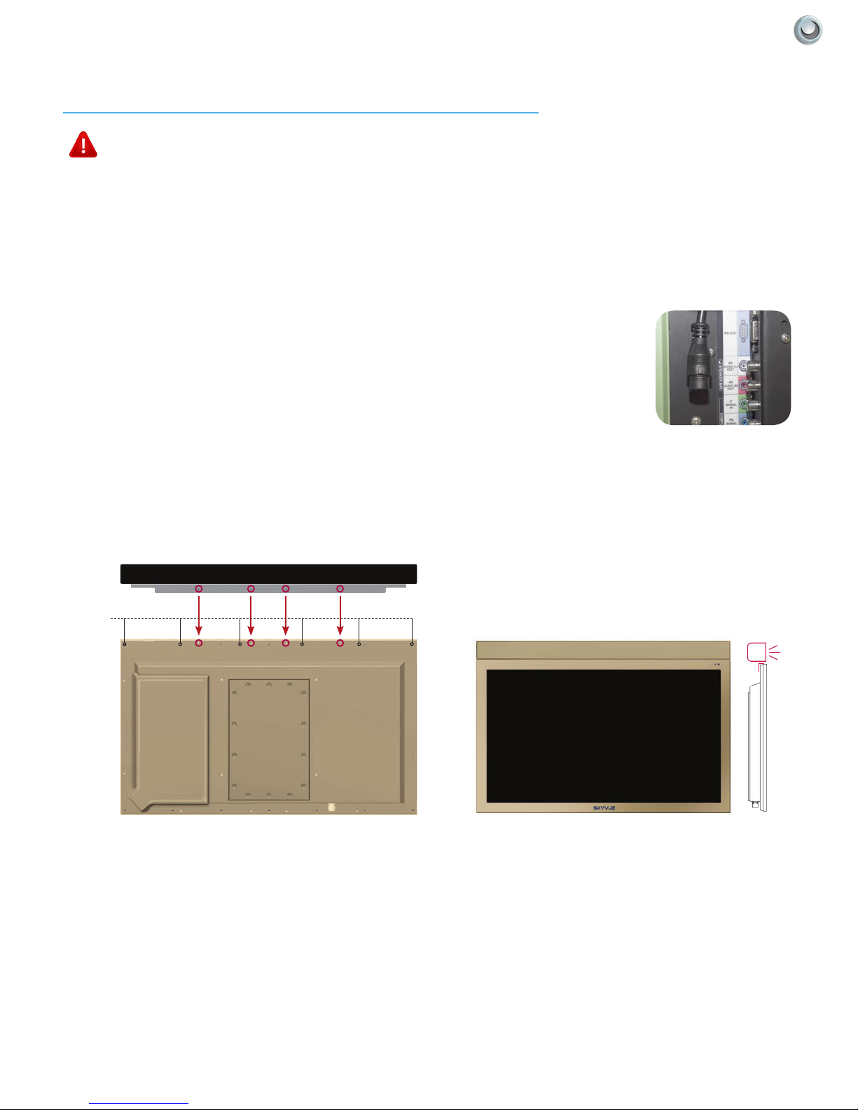
TV Installation - Detachable Speaker Bar
Detachable Speakerbar Installation - Top Mounting
WARNING: Use at least two people when transporting the TV.
Note: If you mount the TV to a ceiling or wall mount, it is best to install the Detachable Speaker Bar before the TV has been
installed.
Tools Needed: Phillips Screwdriver
1. Remove the (4) #8-32 Phillips Head screws in either the top or bottom mount position.
(Refer to Figure 1 below for proper screw removal)
2. Position the Speaker bar in place and secure with the same (4) #8-32 screws that were removed in step 1.
3. Screw securely
4. Loosen the 3 latches, and open the Component Cover.
5. Take the Speaker Bar Cable from the speaker, making sure that the Speaker Bar
Cable Wire is placed on the Rubber Sealing Gasket, and connect at top left of
Component Housing (Refer to Figure A at right)
6. When you close the Component Cover, be sure that the Speaker Bar Cable Wire is
placed over the Rubber Sealing Gasket. As with all wires entering the connection
compartment, leave a drip loop as the wire enters the TV, this will allow water to drip
from the bottom of the loop.
SPEAKER BAR
Do Not
Remove
SPEAKER BAR
MOUNTED
ON TOP
Figure A
Figure 1
15Operator’s Manual - Model NXG-3250 TV Ins Tall aTIo n & Co nne CTI ons |
 Loading...