

Page 1

MOTORIZED SEARCHLIGHT
MiniTracker
INSTRUCTION MANUAL
Equipment Type 3200365 • Rev. December 2004
4350 McKinley Street • Omaha, Nebraska 68112 USA
Tel (402) 453-4444 • Fax (402) 453-7238 • www.skytracker.com
Page 2

PATENT POSITION
The MiniTracker is a motorized, high-intensity, single head searchlight system,
which was originated by SkyTracker of America, Inc. and is proprietary to Strong
Entertainment Lighting/Ballantyne of Omaha, Inc.
Patents, owned by SkyTracker or Ballantyne of Omaha are either issued or pending
in this and related concepts.
TRADEMARK
The name, “MiniTracker” is a trademark owned by Ballantyne of Omaha, and has
been registered with the U.S. Patent Office.
COPYRIGHT
The material contained in this manual is the property of Ballantyne of Omaha, and
may not be reproduced, in full or in part, without the written consent of Ballantyne of
NOTICE
Omaha.
Strong Entertainment Lighting is a division of Ballantyne of Omaha, Inc.
4350 McKinley Street • Omaha, Nebraska 68112 USA
iii
Page 3

INTRODUCTION
The MiniTracker is an original proprietary lighting system developed specifically for the
display advertising industry and related technologies. Each unit is designed with highly
reliable mechanical, electrical and optical components to insure extended, trouble-free
performance. Unlike the full-size SkyTracker Motorized Searchlight systems, the MiniTracker does not require a high voltage, multi-phase AC power source.
Like the SkyTracker, which evolved from from space age and military advanced technology
applications, the MiniTracker provides an easily transported base unit for the mounting and
control of a high intensity searchlight. The light source is a single-ended 1200 watt metal
halide lamp, mounted in a parabolic reflector, yielding a coherent beam of light visible for
great distances. A motorized yoke permits continuous 360° rotation to attract attention.
SAFETY
The concept of achieving maximum safety through knowledge and understanding is basic
to SkyTracker/Strong Entertainment Lighting. This applies to its own personnel, those of
the dealer, representative, operator, servicing agency or to any member of the general
public who may be exposed to or associated with the operation of a SkyTracker/Strong
Entertainment Lighting product.
Safety features and concepts are designed into every SkyTracker/Strong Entertainment
Lighting product and component regardless of whether its function is mechanical, electrical, or optical. Since SkyTracker/Strong Entertainment Lighting has no control over the
manner in which its products are installed, operated, maintained, or utilized after the
product leaves the manufacturing facility, it cannot be held responsible for any injuries
resulting from improper installation, use, inadequate maintenance, or any other condition
beyond its control.
It is the intent of this manual to call to the attention of the owner, operator, and service
technician to any and all hazardous areas or conditions which could lead to operational
problems or injury, and to outline proper and recommended procedures to prevent any
such occurrence.
The normal warranty will be voided in instances where it is determined that any component
of the MiniTracker has been damaged or has failed due to failure to follow procedures or
instructions contained in this manual.
The completely assembled and operational MiniTracker has all electrical and optical
components contained within closed and secured housings. It is recommended that, if
the unit is operated at ground level in areas where crowds may be present, a rope barrier
or equivalent barricade be established to keep the general public away from the unit.
As is the case with all intense light sources, it is not advisable to look directly into the light
source or into the light beam. It is the responsibility of the operator to see that the necessary rope barriers or other barricades are positioned suitably to prevent passers-by or any
member of the crowd from looking directly into the light beam from a close distance.
1
Page 4
SET -UP AND OPERATION
Inspect the unit on arrival and report any damage to the freight carrier immediately. It is
the responsibility of the consignee, not the shipper, to initiate any damage claims. Strong
Entertainment Lighting will provide any required shipping records on request.
The four feet of the MiniTracker base are threaded to permit leveling the unit on an uneven
floor. The leveling feet are adjustable through a two-inch (5cm) range and can be secured
by tightening the locknut provided.
Do not connect the power cord to a receptacle before first installing the metal halide lamp.
The MiniTracker lamphead was designed to use the Philips MSR 1200/2 single-ended
metal halide lamp. This lamp is not supplied with the unit by Strong Entertainment Lighting, and any lamp other then the one noted above must be certified by its manufacturer as
being 100% interchangeable with the specified lamp.
Do not touch the quartz envelope of the metal halide lamp with bare fingers! Skin oils will
burn into the envelope material and shorten lamp life. Alway wear clean cloth gloves or
use a clean towel when handling the lamp. If the envelope is accidentally touched with
bare fingers, remove any fingermarks with alcohol before igniting the lamp.
Dismount the light baffle and front cover of the lamp-
Socket
head by removing the three 10-32 truss head screws
and weathertight washers from the front cover ring.
Locate the two-pin ceramic socket behind the parabolic reflector. Insert the lamp into the reflector,
taking care not to scratch the surface of the reflector
with the metal pins. Seat the lamp pins into the
socket and press the lamp firmly into the socket.
Replace the baffle and front cover; secure all three
screws and their weathertight washers.
Lamp
Front
Cover
Locate the two toggle switches (LAMP and MOTION) on the bottom of the base assembly
and make certain that both are in the OFF positions. Connect the AC power cord to a
grounded 115 volt AC outlet. The cooling fans in the lamphead and in the base will start.
Turn the LAMP switch to the ON position, and the lamp will ignite. Allow three to five
minutes for the metal halide lamp to reach full intensity. Once ignited, leave the lamp burn
throughout its duty cycle; a metal halide lamp does not readily restart when warm.
Lamp focus is set at the factory by positioning the depth of the socket in relation to the
parabolic reflector. This setting should remain unaltered when the correct lamp (noted
previously) is installed. Manufacturing tolerances between individual lamp however will
require fine adjustment of the lamp position after installation.
2
Page 5

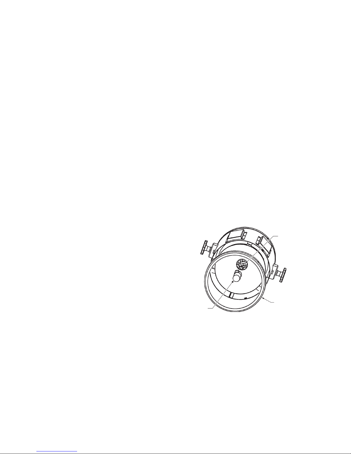
The lamp positioning controls are accessible
“12 o’clock”
through the back cover of the lamphead. Three
clearance holes are located around the center air
intake cap at the twelve, four, and eight o’clock
positions. A #2 phillips screwdriver with a blade
exceeding 6 inches (15.25cm) in length is required.
“8 o’clock”
“4 o’clock”
After nightfall (outdoors) or in a dark room (indoors), observe the column of projected light.
The light may appear brighter on one side of the beam. If so, insert the screwdriver though
one of the clearance holes and locate the phillips-head adjusting screw. Alternately tighten
and loosen the adjusting screw while observing the bright portion of the light. Do not
adjust more than one full turn of the screw. If the bright portion is not centered, try one or
both of the other two adjusting screws. Tighten or loosen the adjusting screws in sequence
while observing the light beam. It will normally take a very minor adjustment of two or all
three screws to center the brightest portion of the beam. A degree of light spillover from
the beam is also normal.
Once the lamp is positioned, set the desired projection angle and tighten both yoke clamping knobs. Turn on the MOTION switch to set the lamhead in motion. The knob adjacent
to the MOTION switch can adjusted to be set to the desired speed of rotation.
At the end of the duty cycle, turn both LAMP and MOTION switches to the OFF positions.
The metal halide lamp does not required a forced-air cooling period, but it will not readily
restart until it has cooled to ambient temperature (approximately 30 minutes).
3
Page 6

MAINTENANCE
Except for unusual conditions of use (dirty environment, flooding, etc.) the frequency of
service and replacement of certain parts and components because of normal wear is
directly related to hours of use.
Inspection and preventive maintenance should be preformed approximately every 250
hours of use or every three months (whichever occurs first). The period can be adjusted
according to actual circumstances.
Lamphead
Clean both surfaces of the front lens on a regular basis. When the lamphead front cover is
removed, clean the surface of the reflector. Normal soiling can be removed from the reflective surface with a clean, dry cloth. If excessively soiled, use a commercial glass cleaning
solvent (i.e. Windex®). Use no abrasives. Before replacing the front cover, inspect the
envelope of the metal halide lamp, and dust off any foreign objects. If excessively soiled,
clean with alcohol and a clean cloth.
The lamphouse fan and intake cover can be dismounted from
the lamphead as an assembly by removing the four phillipshead screws (arrows) adjacent to the lamp position adjustment
holes. A molded plug can then be disconnected from the
blower frame to separate the fan and cover from the lamphead.
Clean the fan blades and keep the intake opening free from
dust or other obstructions. The fan motor requires no oil.
Base Assembly
The motor of the squirrelcage blower in the base requires a few drops of light, non-detergent lubricating oil every 250 hours of use or every three months (whichever occurs first).
The oil holes are marked on the motor housing.
Periodically vacuum or otherwise clean the interior of the base assembly. The heat sink of
the metal halide power supply and the exterior of the motor speed controller must be free
from dust or other obstructions to permit proper cooling. A thermal switch in the lamp
power supply will disable operation of the unit if it overheats. Keep air intakes clean to
allow free air flow.
Both the upper and lower ball bearing pillow block assemblies of the rotating yoke shaft
have easily accessible grease fittings. Check the bearings annually for proper lubrication;
add all-purpose automotive grease as required.
The slip ring attached to the shaft of the yoke assembly transfers electrical current from the
stationary base assembly to the rotating lamphead. Proper maintenance of this item is
mandatory to insure the correct operation of the MiniTracker. Brushes and springs are key
components and are subject to periodic replacement under normal conditions.
4
Page 7
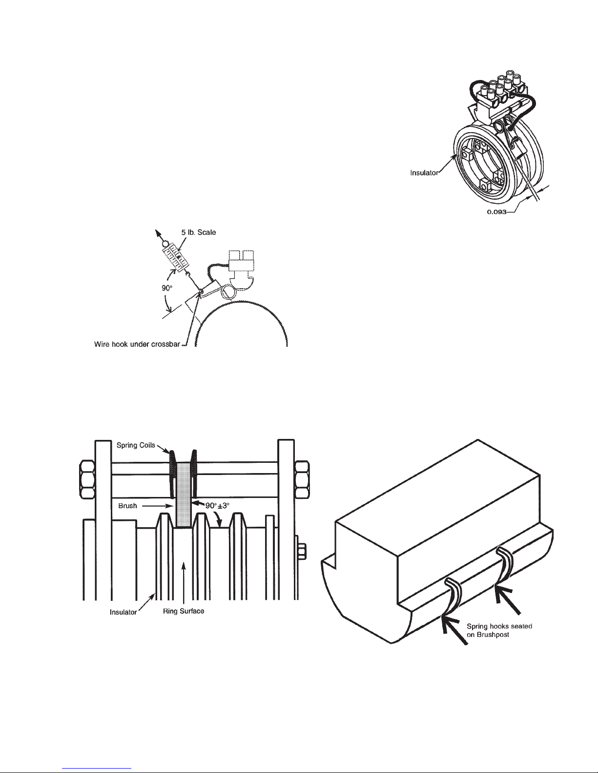
Inspect the brushes for wear. If the distance from the top of
the insulator to the lower part of the brush spring is 0.093 inch
(2mm) or less, replace the brush. Before installing the new
brush, inspect the brush contact surface. Remove surface
dust, oxidation, pitting, or other contaminants with a wire
brush.
It is advisable to replace the brush springs at the same time
to insure proper spring tension. If brush springs fall below
two pounds of tension, continued use will be detrimental to
the slip ring, and the springs must be replaced.
Inspect and test the springs to assure
uniform brush tension. Tension should be
measured at the top center of the brush,
and should exceed two pounds. Replace
the spring if the tension fall below two
pounds. CAUTION: do not lift the spring
more than 1/8 inch (3mm) when measuring
or spring tension may be affected.
All brushes must run at 90° (±3°) square on the rings. If a brush is not square, adjust to
vertical by moving the coil of the spring. Brushes need not run on the exact center of the
rings, but there should be no forceful friction against the insulators. The brush spring
crossbar must be seated in the brush slot, and spring hooks must seat securely on
brushposts.
Contact your Strong Entertainment Lighting distributor for information regarding replacement brushes and springs.
5
Page 8
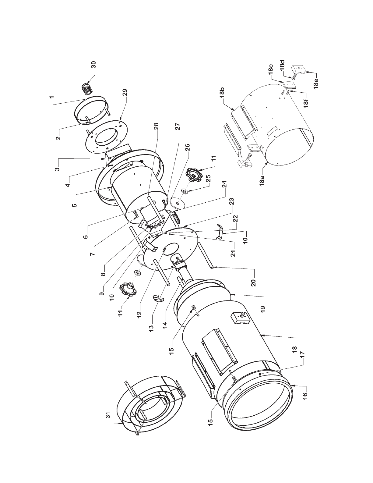
FIGURE 1
MiniTracker Lamphead
Assembly No. 3200387
6
Page 9

PARTS LIST
Figure 1
Item Part No. Description
1 3200407 Blower Intake Cover
2 3200406 Standoff, Intake Cover (4 req’d.)
3 6198002 Lamphead Blower (B1)
- 4082500 Mounting Screw, 8-32 x 2-1/2" Pan Head
4 3200428 Rear Cover Ring
- 4100501 Mounting Screw, 10-32 x 1/2" Truss Head
- 4170114 Weatherseal Washer, #10
5 3200397 Inner Shell
6 3298147 Igniter, 1200 Watt Metal Halide
- 4041500 Mounting Screw, 4-40 x 1-1/2" Pan Head
7 4081251 Screw, 8-32 x 1-1/4" Socket Head (3 req’d.)
8 3140024 Nylon Plug, .375" (3 req’d.)
9 5158060 Compression Spring (3 req’d.)
10 3200400 Reflector Spring (3 req’d.)
- 4100371 Mounting Screw, 10-32 x 3/8" Pan Head
11 45153000 Clamping Knob (2 req’d.)
12 3135009 Nutsert, 8-32 (3 req’d.)
13 7140016 Socket, G22
- 4081250 Mounting Screw, 8-32 x 1-1/4" Button Head
14 --- Metal Halide Lamp, 1200 Watt Single-Ended (by Customer)
15 4108021 Tinnerman Nut, #10 (6 req’d.)
16 3200415 Front Cover Ring
17 3200426 Front Lens
- 1198062 RTV Silicone Sealant (3 oz. Tube)
18 3200388 Lamphead Housing Assembly
18a 3200389 Housing Shell
18b 3200399 Air Channel (2 req’d.)
18c 3200392 Inner Yoke Bracket (2 req’d.)
18d 4501500 Screw, 1/2-20 x 1-3/4" Hex Head (2 req’d.)
18e 3200391 Outer Yoke Bracket (2 req’d.)
18f 4251002 Screw, 1/4-20 x 1" Socket Head (2 req’d.)
19 3130254 Reflector Assembly
20 4100371 Mounting Screw, 10-32 x 3/8" Pan Head (ref. Item 10)
21 4198043 Rubber Grommet
22 4088007 Hexnut, 8-32 Locking (2 req’d.)
23 3200394 Focus Plate
24 2162008 Barrier Strip
25 4170072 Flat Washer, 1/2" (2 req’d.)
26 45151000 Friction Washer (2 req’d.)
27 3200402 Bulb Adjustment Plate
28 3200395 Focus Plate Standoff (3 req’d.)
20 3200396 Reflector Standoff (3 req’d.)
7
Page 10
PARTS LIST, Figure 1 (continued)
Item Part No. Description
29 3200402 Blower Mounting Plate
- 4080375 Mounting Screw, 8-32 x 3/8" Pan Head (4 req’d.)
30 3198164 Heyco Strain Relief Bushing
31 3200537 Light Baffle
- 4100501 Mounting Screw, 10-32 x 1/2" Truss Head
- 4170114 Weatherseal Washer, #10
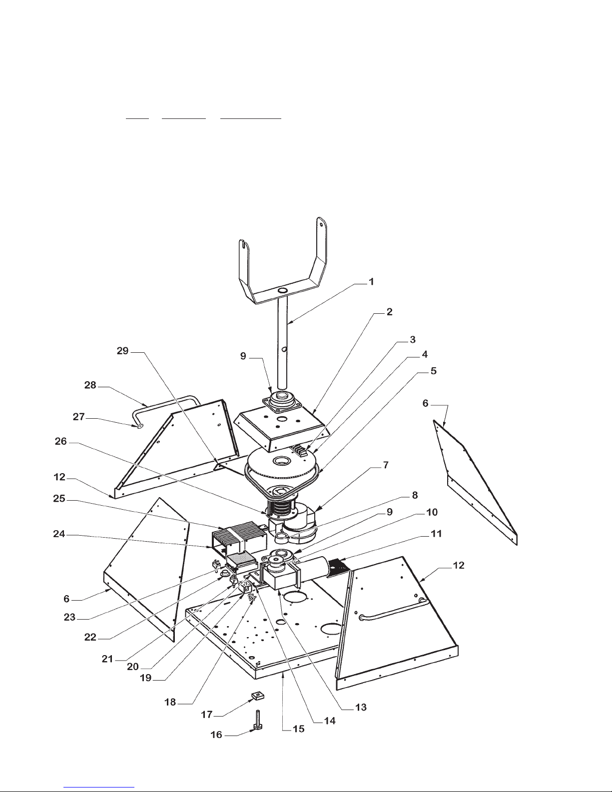
FIGURE 2
MiniTracker Base
Assembly No.3200366
8
Page 11

PARTS LIST
Figure 2
Item Part No. Description
1 3200375 Yoke & Column, Welded Assembly
2 3200372 Top Cap
- 4100371 Mounting Screw, 10-32 x 3/8" Pan Head
3 8162004 Barrier Strip
- 4100751 Mounting Screw, 10-32 x 3/4" Pan Head
4 3200416 Driven Sprocket
5 3198118 Roller Chain (3.69 feet req’d.)
- 3198119 Master Link
6 3200368 End Panel (2 req’d.)
- 4100371 Mounting Screw, 10-32 x 3/8" Pan Head
7 39938000 Squirrelcage Blower Assembly, 115 V.AC, 50/60 Hz. (B2)
- 4080506 Mounting Screw, 8-32 x 1/2" Pan Head
8 3107005 Taper Lock Bushing, 1-3/8" I.D.
9 3104039 Pillow Block & Bearing Assembly (2 req’d.)
- 4501500 Mounting Screw, 1/2-13 x 1-1/2" Hex Head
- 4507100 Flat Washer, 1/2"
- 4507001 Split Lockwasher, 1/2"
- 4508001 Hexnut, 1/2-13
10 3159006 Drive Sprocket
11 83131000 Blower Intake Grille
- 4100371 Mounting Screw, 10-32 x 3/8" Pan Head
12 3200376 Side Panel (2 req’d.)
- 4100371 Mounting Screw, 10-32 x 3/8" Pan Head
13 3133025 Gear Motor, 90 V.DC (M1)
- 4251003 Mounting Screw, 1/4-20 x 1" Hex Head
14 3200429 Motor Mounting Plate
- 4080506 Mounting Screw, 8-32 x 1/2" Pan Head
15 3200367 Base Plate
16 49226000 Leveling Foot (4 req’d.)
- 4508001 Locknut, 1/2-13 (not shown)
17 3200380 Mounting Block (4 req’d.)
- 410050B Mounting Screw, 10-32 x 1/2" Pan Head
18 4113004 Strain Relief, Squeeze Connector
- 3140007 AC Power Cord with Molded Plug (not shown)
19 3162010 Terminal Block
- 4060750 Mounting Screw, 6-32 x 3/4" Pan Head
20 3200377 Motor Bracket
- 4250752 Mounting Screw, 1/4-20 x 3/4" Hex Head
21 3161048 Toggle Switch, DPDT (S1,S2), 2 req’d.
22 3133003 Dial, Motor Speed Controller
23 3133003 Motor Speed Controller (R1)
- 4100371 Mounting Screw, 10-32 x 3/8" Pan Head
9
Page 12

PARTS LIST, Figure 2 (continued)
Item Part No. Description
24 25444000 Lamp Power Supply, 1200 Watt
25 3200378 Power Supply Retaining Strap
- 4100371 Mounting Screw, 10-32 x 3/8" Pan Head
26 3140043 Slip Ring Assembly
27 4377103 Flat Washer, 3/8" (8 Req’d.)
28 49342000 Handle, Chromed (2 req’d.)
- 4310500 Mounting Screw, 5/16-18 x 1/2" Hex Head
- 4317001 Lockwasher, 5/16"
29 3200379 Rotor Bracket
- 4100371 Mounting Screw, 10-32 x 3/8" Pan Head
SkyTracker/Strong Entertainment Lighting
EQUIPMENT W ARRANTY
SkyTracker/Strong Entertainment Lighting agrees that its products shall be free from
defects in materials and workmanship for a period of one year, from the date of original
shipment from its factory. This warranty is nontransferable and applies to the original
purchaser only. Said warranty will not apply if equipment is used in conditions of service
for which it is not specifically intended. The manufacturer is not responsible for damage to
its apparatus through improper installation, physical damage or poor operating practice.
If any device is found to be defective under the warranty, the buyer should notify the
manufacturer. Such equipment will be repaired or replaced, at manufacturer’s option, free
of all charge except transportation, F. O. B. its factory. Any such repair or replacement by
the manufacturer shall constitute fulfillment of all obligations to the purchaser. This
warranty does not include troubleshooting expense, labor charges associated with service
calls, and disassembly or reassembly of the lamp system. Should such a repair or
replacement require an on-site service call, the Purchaser shall bear the responsibility for
all costs and associated expenses. The manufacturer does not assume responsibility for
any unauthorized repairs to its products, even though defective, and unauthorized parts or
repairs shall void this warranty.
This warranty is the only warranty given with the manufacturer’s products. There are no
warranties of merchantability of fitness for a particular purpose or other warranties or
representations of any kind, express or implied, which are made with respect to these
products.
The remedies of the Owner set forth in this warranty are exclusive. In no event shall the
buyer be entitled to recover for incidental, special or consequential damages, arising from
the sale or use of these products, including but not limited to loss of profits or revenue,
other commercial losses, inconvenience, delay, labor, repairs, or other cost of rental or
replacement equipment.
10
Page 13
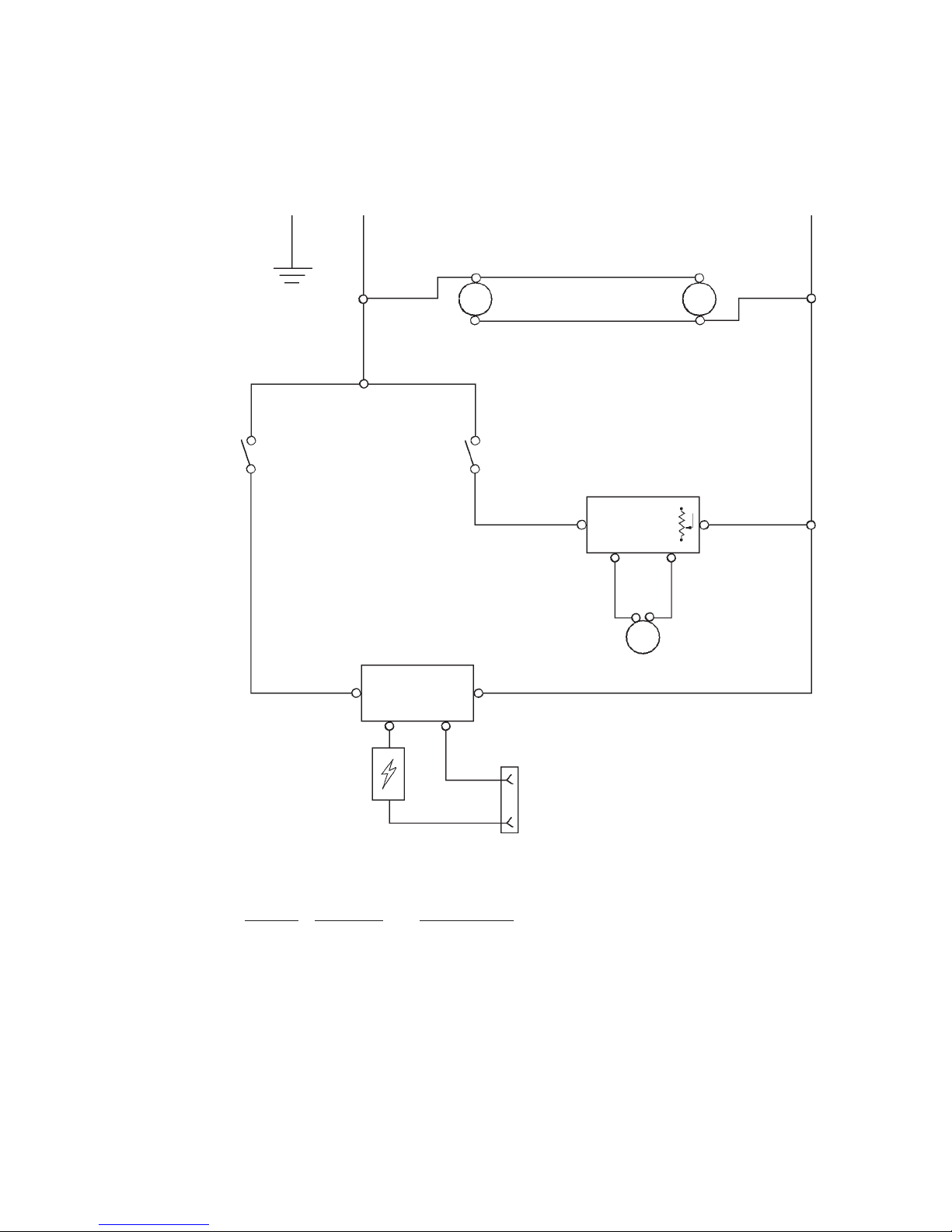
WIRING DIAGRAM
MiniTracker
AC Phase
S1 “LAMP” S2 “MOTION”
AC Neutral
B1 B2
MOTOR
SPEED
CONTROL
R1
M1
LAMP POWER
SUPPLY
J1
IGNITER
SOCKET,
TYPE G22
Ref.
Desig. Part No. Description
B1 6198002 Lamphead Blower, 115 V.AC, 50\60 Hz.
B2 39938000 Base Blower, 115 V.AC, 50\60 Hz.
J1 7140016 Lamp Socket, Two-Pin, Type G22
M1 3133025 Gear Motor, 90 V.DC
R1 3133003 Motor Speed Controller
S1 3161048 Switch, DPDT; “LAMP”
S2 3161048 Switch, DPDT; “MOTION”
- 25444000 Metal Halide Power Supply, 1200 Watt
- 3198147 Metal Halide Lamp Igniter Assembly
11
Page 14

 Loading...