

Page 1
MODELS:
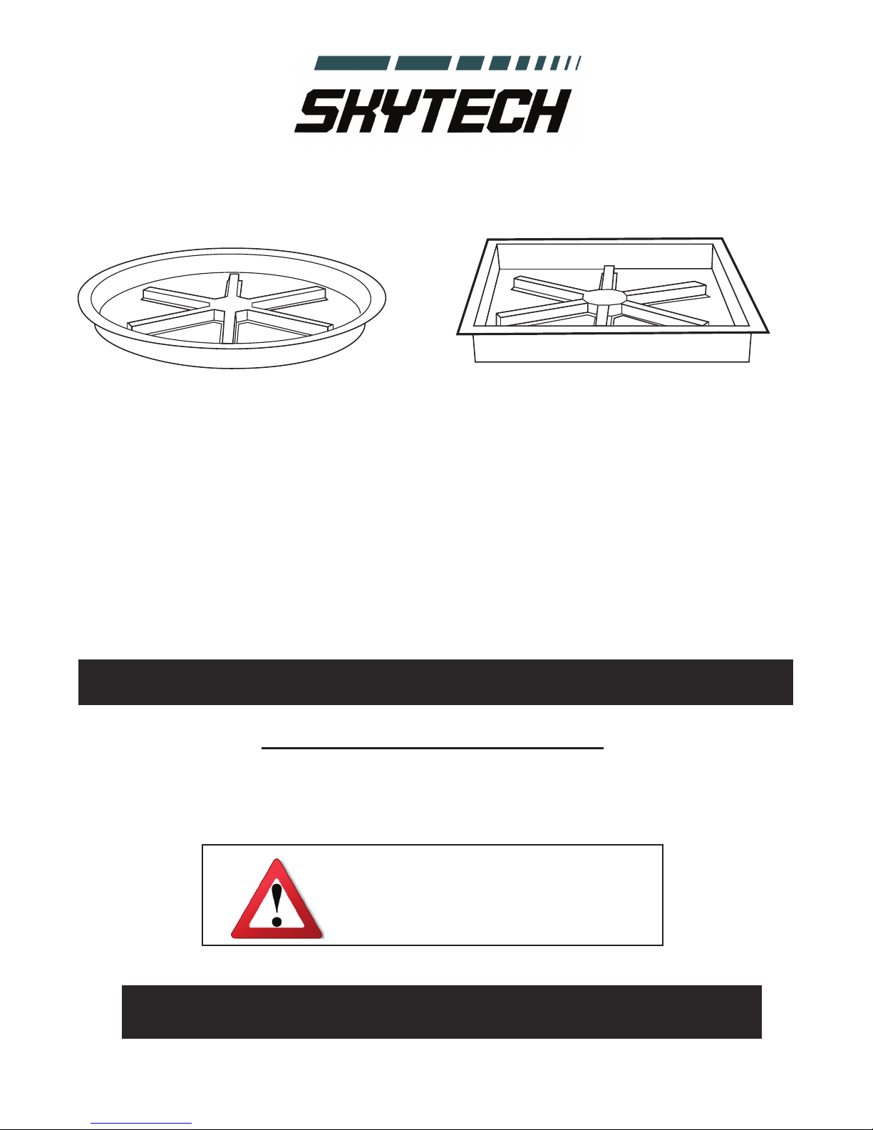
SFRSR19DSI (19-inch Round Fire Pit)
SFRSR25DSI (25-inch Round Fire Pit)
SFRSS20DSI (20-inch Square Fire Pit)
SFRSS26DSI (26-inch Square Fire Pit)
MODELS:
Outdoor Fire Pit
Installation and Operating Instructions
IF YOU CANNOT READ OR UNDERSTAND THESE INSTALLATION INSTRUCTIONS DO
NOT ATTEMPT TO INSTALL OR OPERATE THIS APPLIANCE
INSTALLTION PRECAUTION:
This re pit requires a minimum 18-square inches of cross ventilation. Failure to
provide proper ventilation can void the warranty.
PLEASE RETAIN THIS MANUAL FOR FUTURE REFERENCE
Warning: For Outdoor Use Only
Page 2
!! !!!"#$%&!
!
"#!$%&!'()**!+,'-!
!
1. Shut off gas to the appliance.
2. Extinguish any open flame.
3. If odor continues, keep away
from the appliance and
immediately call your gas
supplier or fire department.
!!'"&#(#$!
!
.%!/%0!'0%1)!%1!&')!+,'%*2/)!%1!%03)1!
#*,((,4*)!5,6%1'!,/7!*28&27'!2/!03)!
5292/20$!%#!032'!%1!%03)1!,66*2,/9):!
!
;/!<=>9$*2/7)1!/%0!9%//)90)7!#%1!&')!
'3,**!/%0!4)!'0%1)7!2/!03)!5292/20$!%#!032'!
%1!,/$!%03)1!,66*2,/9):!
!!!"#$%&! ! ! )"&*+#,-+#+.(!%,/"00"&!,
,
1234,56673589:,958,6;<=>9:,95;?<8,@<8<A3=:,
B2392,254,8<,<=<;C,
,
D438E,3F,38,58,:897<4:=,4659:,958,G377,H<>C,
,
#:I:;,>4:,F234,56673589:,38,58,:897<4:=,4659:,
4>92,54,5,95@6:;J,F:8FJ,95;,<;,2<@:C,
!
'"&#(#$-!!"#!03)!2/#%1(,02%/!2/!03)')!2/'01&902%/'!2'!/%0!#%**%?)7!)@,90*$A!,!#21)!%1!
)@6*%'2%/!(,$!1)'&*0!9,&'2/+!61%6)10$!7,(,+)A!6)1'%/,*!2/B&1$!%1!7),03:!
!
K+&,L+D&,M"K%1L,
.%!/%!'0%1)!%1!&')!+,'%*2/)!%1!%03)1!#*,((,4*)!5,6%1'!,/7!*28&27'!2/!03)!5292/20$!%#!
032'!%1!,/%03)1!,66*2,/9):!
!! !!'"&#(#$!
"(61%6)1!2/'0,**,02%/A!,7B&'0()/0A!
,*0)1,02%/A!')1529)!%1!(,2/0)/,/9)!9,/!
9,&')!2/B&1$!%1!61%6)10$!7,(,+):!!C),7!
03)!2/'0,**,02%/A!%6)1,02/+!,/7!
(,2/0)/,/9)!2/'01&902%/'!03%1%&+3*$!
4)#%1)!2/'0,**2/+!%1!')15292/+!032'!
)8&26()/0!!!!!!
'"&#(#$,
.%!/%0!*),5)!&/,00)/7)7!7&12/+!&'):!
.%!/%0!&')!#%1!9%%D2/+:!
E%**%?!,**!+,'!*),D!61%9)7&1)'!2/!032'!
(,/&,*!612%1!0%!%6)1,02%/:!
Skytech Fire Pits
REV. 1-6-12 Page 1
Page 3

!
"#$%&!#&$'!()!*+&!,(-$'!+..%(+)/$&0!+)'!12$!.-3'#/1&!3,!/345#&1(3)!3,!&#/2!,#$%&0!/3)1+()!
/2$4(/+%&!6)37!13!12$!81+1$!3,!9+%(,3-)(+!13!/+#&$!/+)/$-0!5(-12!'$,$/1&!+)':3-!312$-!-$.-3'#/1(;$!
2+-4<!=2(&!7+-)()*!(&!(&&#$'!.#-&#+)1!13!9+%(,3-)(+!>$+%12!?!8+,$1@!93'$!8$/<ABACD<E!
TABLE OF CONTENTS
Specications 3
Preparation for Non-Conbustible Structure
Hard Piping to Fire Pit 4
Cross Ventilation Requirements 4
Installation Into An Approved Enclosure
Requirements 5
Installation of Battery Pack 6
Installation of Lava Rock/Media 6
Learning the Remote to Module 7
Operation
Initial Start Up 8
Replacement Parts 9
Replacement Parts List 10
Fire Pit Maintenance 11
Trouble Shooting 11
Wiring Diagram 12
Accessory Parts 13
Warranty 14
Skytech Fire Pits
REV. 1-6-12 Page 2
Page 4
36”
96”
24”
Maximum
Overhang
Center of Flame
!
MODEL: SFRS19DSI SFRS25DSI
INSTALL
HEIGHT
(MINIMUM)
INSTALL
DIAMETER
(MIN/MAX)
18 " 18"
20" / 21" 26" / 27"
D1
D2
H1
H2
H3
W1
19"
21.75"
2.5"
4.5"
6"
10.5"
25"
27.75"
2.5"
4.5"
6"
10.5"
ALL DIMENSIONS ARE NOMI
UNLESS OTHERWISE N
D2
INSTALL DIAMETER
D1
H1
H2
H3
W1
GROUND LEVEL
INSTALL HEIGHT
MODEL SFRS19DSI SFRS25DSI SFRSS20DSI SFRSS26DSI
MINIMUM
INSTALL
HEIGHT
INSTALL
OPENING
(Min/Max)
D1 19” 25” 20” 26”
D2 21.75” 27.75” 22” 28”
H1 2.5” 2.5” 2.5” 2.5”
H2 4.5” 4.5” 4.5” 4.5”
H3 6” 6’” 6” 6”
W1 10.5” 10.5” 10.5” 10.5”
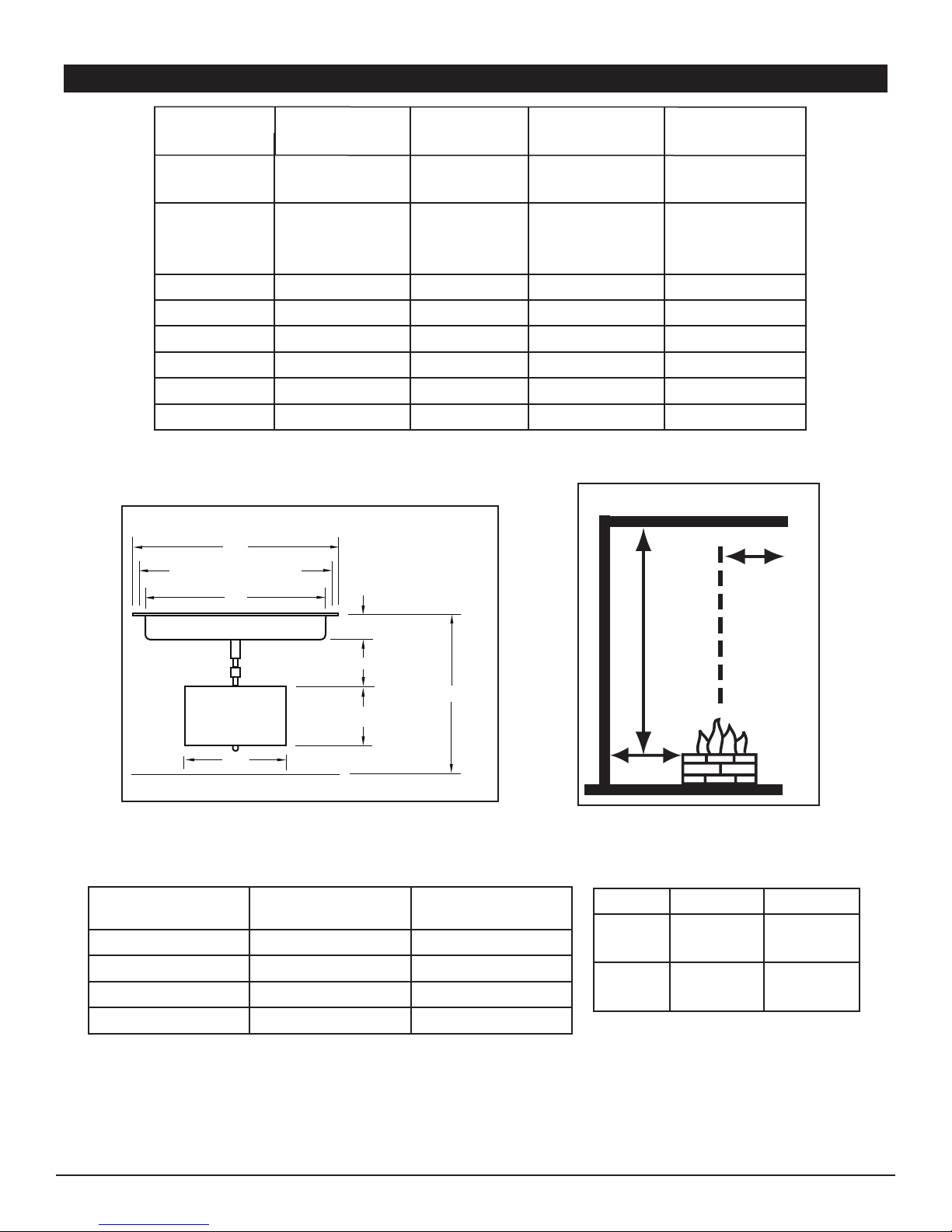
Table1. Fire Pit Dimensions
SPECIFICATIONS
18” 18” 18” 18”
20” / 21” Di-
ameter
26” / 27”
Diameter
21” / 22”
Square
27” / 28”
Square
Figure 1. Fire Pit Dimensions (refer to Table 1)
Model
High Btu’s
Natural/Propane (LP)
SFRSR 19DSI 80,000 Btu’s 50,000 Btu’s
SFRSR 25DSI 110,000 Btu’s 50,000 Btu’s
SFRSS 20DSI 80,000 Btu’s 50,000 Btu’s
SFRSS 26DSI 110,000 Btu’s 50,000 Btu’s
Table 2. Btu Specications
Skytech Fire Pits
Low Btu’s
Natural/Propane (LP)
Figure 2. Clearance to Combustibles
NG LP
Min.
5.0”WC 11.0”WC
Inlet
Max.
10.5”WC 13.0”WC
Inlet
Table 3. Gas Pressures
REV. 1-6-12 Page 3
Page 5
WARNING: Proper clearances from combustible, construction and materials must be maintained from all sides, top and
Fire Pit
Enclousure
2”x3”
Fire Pit
Examples of Cross Ventilation
3 - 2”x3” Slots Each Side
2- 1” x 9” Slots Each Side
Cross Flow Ventilation
(Min. 18 Sq. In. Per Side)
bottom of this appliance. This appliance should never be placed on any combustible surface. This appliance should
never be placed under any combustibles closer then 96-inches. This appliance should never be placed closer than
36-inches from any side to any combustible construction or materials (See g. 2, page 3).
PREPARING A NON-COMBUSTIBLE STRUCTURE
The Fire Pit is to be installed on a at, stable surface, away from any combustible materials. Install Fire Pit on any level,
outdoor non-combustible surface. NOTE: Do not place re pit directly on grass, dirt, or rocks this may prevent proper
ventilation (Fig. 1, pg. 3).
HARD PIPING TO FIRE PIT WITHOUT GAS PROXIMITY
1. Turn OFF gas supply system. NOTE: All gas connections (except for brass to brass) require the following. Clean pipe
threads using either a wire brush or steel wool. Apply Teon tape or pipe sealant to the steel ttings before making any
connection. BE CAREFUL! Ensure all gas connections are snug, but not over tighten!
2. Extend the gas supply system using minimum of ¾” black iron pipe or an approved exible gas line from existing house
supply. This can be accomplished by teeing off or tapping into a convenient gas line connection. Install necessary pipe for
the distance required and then install a manual shut-off valve at the exterior house wall. If pipe is to pass through a foundation or house wall, make sure to re-seal the area around the pipe with weather sealant.
3. From manual valve, extend gas pipe to the Fire Pit location. NOTE: If pipe is to be placed in an underground trench,
check with local codes for required depth and materials needed.
4. Install a ¾” female x ½” male ared brass tting to the end of the ¾” black iron pipe. Be sure to clean the pipe threads
and use Teon tape or pipe sealant.
5. Connect the ½” female ared ex connector from the Fire Pit to the ½” male ared brass tting secured to the black iron
pipe. Note: Flare to are connections do not require Teon tape or pipe sealant.
IMPORTANT
Installation of Natural or LP gas should be done by a qualied installer, service agency or gas supplier.
The appliance and its manual shutoff valve must be disconnected from the gas supply piping system during any
pressure testing of the system at test pressure testing of the system at test pressures in excess of ½ psig (3.5kPa).
This appliance must be isolated from the gas supply piping system by closing its manual shutoff valve during any
pressure testing of the gas supply piping system at test pressures equal to or less than ½ psig (3.5kPa)
NOTE: LP conversion kits are available in the accessory section of this manual. When converting a Fire Pit ensure you
follow the instructions supplied with the conversion kit.
VENTILATION FOR NON-COMBUSTIBLE ENCLOSURE
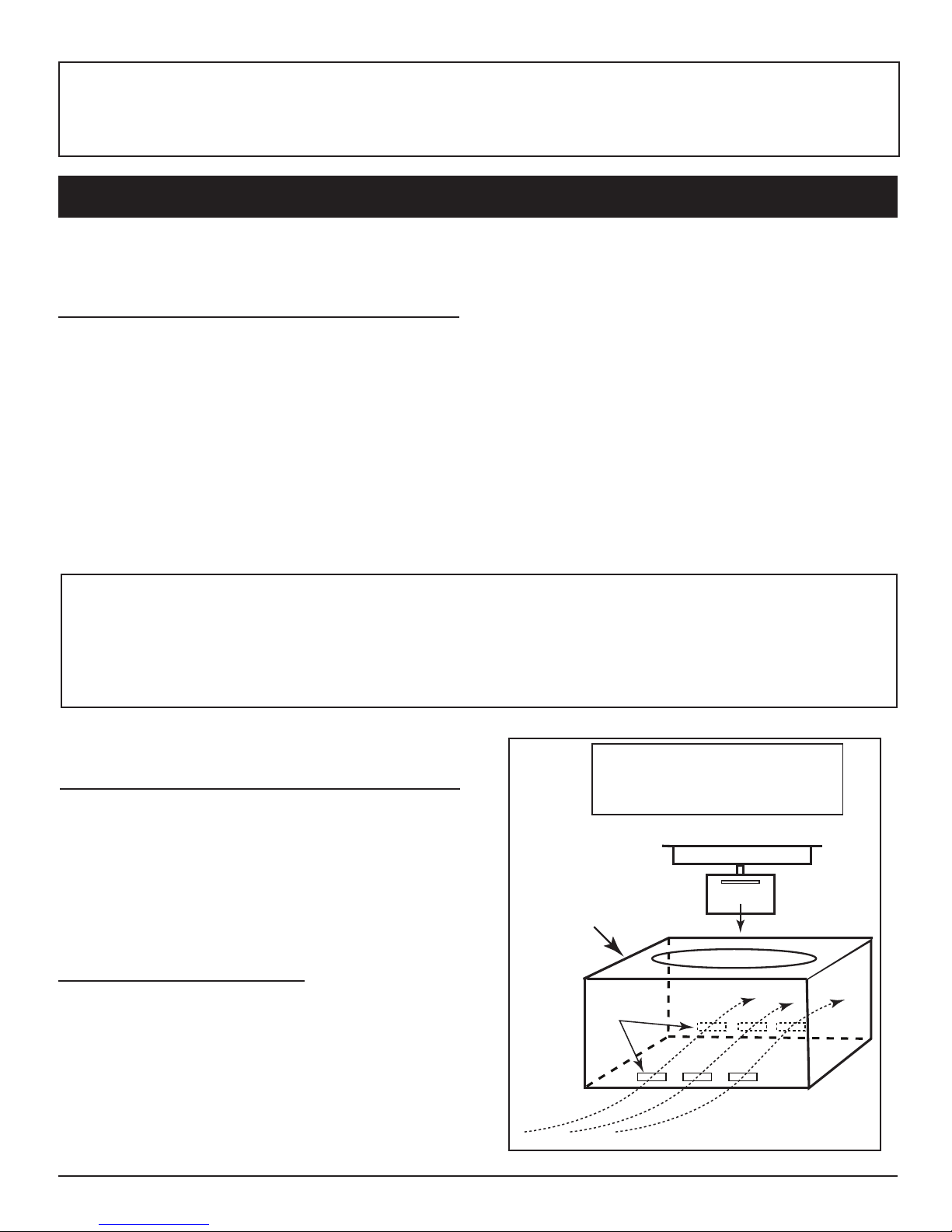
Fire pits are subjected to many outdoor elements such as
rain, snow, wind, heat or cold. These re pits have electronic
components that need to remain dry as possible in order to
operate properly. A minimum of 18 square inches of cross
ventilation (2 sides) is required to keep the components in
good working order. Use gure 3 as guide to assist to incor-
porate proper ventilation. NOTE: Ventilation is not required at
the bottom and may also be incorporated in the upper portion
of an enclosure.
HIGH ELEVATION INSTALLATION
This appliance is listed for elevations from 0-4500 feet in
Canada and the U.S. If elevation exceeds 4500 feet it may be
necessary to decrease the input rating by changing the existing burner orice to a smaller size. Input should be reduced
4% for each 1000 feet beyond the 4500 feet above sea level.
Check with your local gas utility for assistance in determining
the proper orice in your location. In some cases the heating
value may already be reduced and downsizing the orice may
not be necessary.
Skytech Fire Pits
Figure 3. Cross Ventilation Example
REV. 1-6-12 Page 4
Page 6

INSTALLATION OF FIRE PIT INTO AN APPROVED ENCLOSURE
REQUIREMENTS
1. Only non-combustible materials should come in direct contact with any part of the Fire Pit. Underneath area should
be non-combustible as well.
2. Only use ¾” gas supply line to the Fire Pit. Based on the selection of the re pit size, the proper brass ttings should
be used to ensure a proper installation.
3. Determine the size of the round or square Fire Pit you are preparing to install (Refer to page 3).
4. You must provide a round or square cut out to place the re pit into the non-combustible enclosure surround. Use
the pattern from the shipping carton for sizing.
5. Follow the local code requirements for the gas type being used. This Fire Pit should be installed in accordance with
local codes and ordinances or in the absence of local codes, with the latest National Fuel Gas Code, ANSI Z223.1
NFPA54 or CSA B149.1, Natural and Propane Installation Code in Canada.
6. Fire Pits create high temperatures, it is very important to have any combustibles at a safe distance.
7. Normal operation of the Fire Pit is with a battery box that is supplied with your system (Fig 4). The battery box has
12-feet of black sleeved wire that is to be passed through the junction box provided. This wire should not be cut or
spliced and the junction box can be placed in the facing of the vertical nish of the re pit, if you place the wire under
ground you should install those wires into an approved protective conduit/sleeve material.
8. If (optional) 120VAC adapter (Pg.13) is going to be used to power this system it is required to follow all local codes
or National Electrical Code ANSI/NFPA 70 for installation of this electrical outlet. A breaker on wall switch with
approved outdoor outlet must be used to insure safety to this Fire Pit. When not in use the breaker should be in the
OFF position.
9. Fire pit should never be left unattended while in operation. It should always be a safe distance from all trees and
combustible landscape materials.
10. Construction of the nished re pit should be stable and solid. From the bottom of the control box that houses the
gas valve and module, it should be a minimum if of 4-inches to the ground level. See gure #1. Drainage is critical to
ensure that water does not damage and valve components. Never install the re ring system below grade.
11. CAUTION: A minimum of 18 square inches of cross ventilation (2 sides) is required to keep the components
in good working order.
12. The insulation square pad provided with the Fire Pit is to be placed foil up toward the bottom of pan on top of the
valve box.
13. Never ll the cavity under and around the valve box with any material, this is a provided air space necessary for
ventilation.
14. These products are designed for outdoor use only. Not approved for any indoor use.
15. This Fire Pit is designed to have decorative rock, Lava rock/Media covering the spoke burner. Optional concrete
logs can be added to consumers taste. Decorative Rock is not provided. When purchasing decorative rock it is
recommended to use minimum of 1-inch diameter rock as a base to ll the burner pan. Decorative glass cover
ing may be loosely scattered on top of rock if desired or non-combustible logs may be added for a campre look.
NOTE: If using all glass media, glass must be a minimum of 1/4-inch diameter or larger.
16. Gas lines and ttings must be installed in to the non-combustible structure. All gas connections must be leak tested
before installation of the re pit. Soapy water leak detection is required before regular use of the re pit.
17. Do not use material that will absorb moisture over time and will not release this moisture quickly. Moisture can boil
in this material and can rapidly break apart and cause damage or personal injury.
18. Never leave any other combustible material on top of the re pit. This could cause unsafe operation of this system
and damage to the component that will not be covered under our warranty.
19. Cover the complete burner with lava or decorative Rock material (min. 1-inch diameter). Completely cover the
spoke burner, no more than 1 inch above the burner.
Skytech Fire Pits
REV. 1-6-12 Page 5
Page 7

INSTALLATION OF BATTERY PACK
Requires 4-AA 1.5V
alkaline batteries
B
a
ttery cove
r slid
es on/off
La
tching
S
olenoid
D
C Moto
r Driv
e
Slide Switch
to Latching
Solenoid
Lava Rock
Lava Rock
Lava Rock
Ignition Hood
Screen Cover
1. During the installation the location of the Battery Pack should be installed in the location that is easy to service.
The best location is in the vertical enclosure of the Fire Pit. The plastic junction box is provided for the installation
of the battery pack.
2. The wiring extending from the valve box is a 12-foot special 4-pin connector that connects to the battery pack and
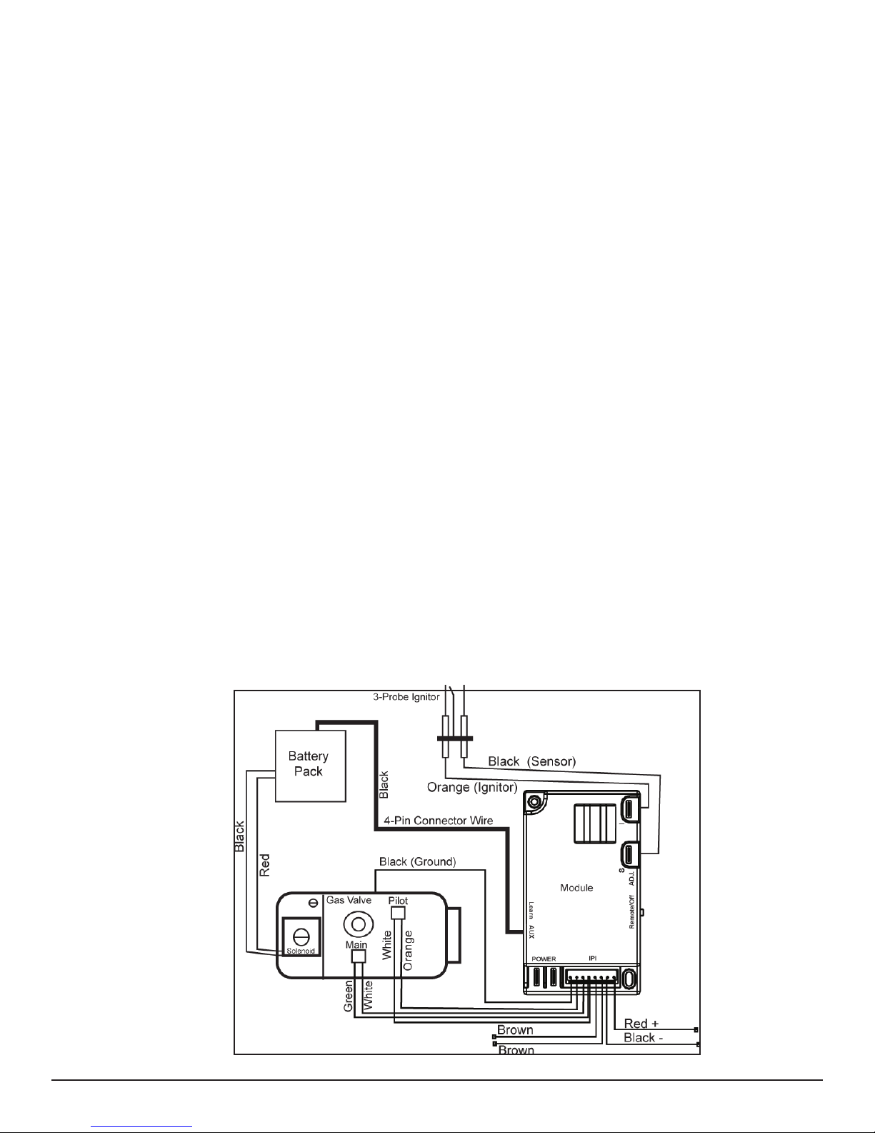
(2) two additional wires with 1/4’’ female connectors. A complete wiring diagram (Fig.12) is located on page 12.
3. Feed all wires into the plastic junction box and connect special 4-pin plug into back of the battery pack. Connect
1/4’’ female spade connectors to solenoid wires matching color, red-to-red and black-to-black.
4. Install the (4) AA batteries in to the battery compartment shown in gure 5. Double check to ensure the slide
switch is in the Latching Solenoid position on the battery pack. Then snap cover plate in place as shown in g.6.
Figure 6. Slide switch on latching solenoid
Figure 7. Cover plate installation
NOTE: If using optional 120V power adapter (AF-4000ADP24), you must use a switch or a breaker that can be turned
ON and OFF easily. Normal operations are with battery power, and nothing else would have to be done.
5. Reinstall the battery box into the plastic junction box, line up the two holes in the cover and install white screws
provided. Batteries can be changed or installed by removing the two screws that hold the cover plate battery box
in place. Remove assembly, slide cover away from the cover plate and install the (4) four AA batteries.
6. Be sure the batteries are installed positive-to-positive and negative-to-negative. If one battery is installed wrong
the system will not operate.
7. Once the re pit is installed into the enclosure, the burner and control system should be tested before the media
(lava rock) is installed.
INSTALLATION OF BATTERY INTO TRANSMITTER
You have one handheld transmitter (model RCAF-3) and you will need to install the included A23 (12-volt battery) into the
transmitter. On the backside of the transmitter, push the cover away from the case. Place the battery into the compartment matching positive-to-positive and negative-to-negative. To ensure the battery is properly installed push any button
on the transmitter and you will see a red LED light at the top of the transmitter glow. The LED light will only be lit when a
button is pushed.
INSTALLATION OF LAVA ROCK/MEDIA INTO BURNER PAN
Install lava rock/media into the burner pan. Ensure the media is a minimum of 1-inch diameter for proper operation.
Note: Do not pour Lava Rock directly from bag. Media should be placed naturally and NOT packed in tight. Loose tting
is important to ensure robust ames. Be sure rocks are free of any
excessive dust. This prevents the burner pan weep holes from being
plugged and holding water. IMPORTANT: Do not place media over
top or under the screen cover. The screen must be free of any debris to
ensure proper lighting of burner and good ame rectication (See g. 8).
Cover the burner completely with media but do not make the depth
greater than 1-inch overtop of the burner portholes.
Decorative glass may be loosely scattered on top of the lava rock. Do
NOT cover the stainless steel screen cover with any rock or glass. It
must be free an any debris to operate properly.
Skytech Fire Pits
Fig. 8 Keep screen cover exposed
REV. 1-6-12 Page 6
Page 8
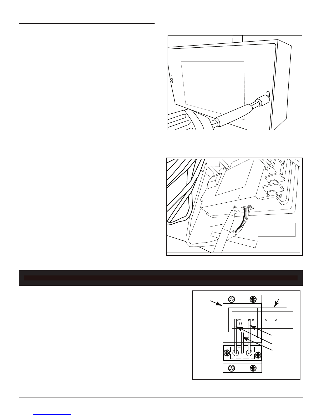
LEARNING THE REMOTE CONTROL TO THE MODULE
Learn Button
AU X
POWER
PEN
MODULE
INSIDE FIRE PIT
METAL BOX
Fire Pit Valve Box
Ignition
Hood
Spoke Burner
Sensor
Ignitor
Ground
The Skytech Fire Pit is unique that it comes standard with one
remote controlled transmitter (Model RCAF-3). The handheld
remote is shipped with this system are already learned (programmed) to the module inside the control box. Additional
transmitters can be learned to this electronic module; up to
a total of three Skytech transmitters are available. Contact
Skytech to discuss additional transmitter options or see the
accessory page of this instruction manual.
Matching new transmitters is simple, but will require pressing
the learn button on the module. You should learn any new
transmitters before the nal installation of the Skytech Fire
Pit. Follow the steps below:
1. Remove the two screws securing the cover on the
control box (See g. 9). The cover will slide
down exposing the gas valve and control module.
2. Find the black module attached to the inside of the
control box. Locate the “Learn Button” on the bottom
of the module.
3. Once the Learn button is located, press and release
the button once. You will hear a beep indicating that
the module is ready to receive a transmitter code
(See g. 10)
Fig. 9 Removing the cover from metal box.
4. Take the transmitter and press the OFF button. You
will hear a series of rapid beeps indicating the module
has accepted the new code.
NOTE: A maximum of three (3) codes can be programmed
to the module. After a total of three (3) codes have been programmed the memory is full and will not accept any additional
codes. To clear all codes, press and hold the learn button for
10 seconds. The module will beep three (3) times indicating the memory is clear of all codes. After codes have been
cleared see to Step #3 above to re-learn transmitter.
For proper ignition it is important that the ignitor probe be properly aligned
overtop of the burner. Use the Fig. 11 as a guide. Before lighting remove
any tape holding the screen cover of the ignition hood to the burner and
ensure the spark and sensor probes are directly overtop of a burner port
hole. The sparking and sensor probes must be in the path of a ame to
ignite the gas and the sense that ame is present for continued operation.
Replace the screen cover and follow the operating procedures.
Fig. 10 Learn button location
READ BEFORE OPERATING
Skytech Fire Pits
Fig. 11 Top View of Ignitor
REV. 1-6-12 Page 7
Page 9
OPERATION
To Close
CAUTION: Children and adults should be alerted to the hazards on high surface temperatures and should stay away to
avoid burns or clothing ignition. Young children should be carefully supervised when they are in the area of the appliance.
WARNING: Do not use this appliance if any part has been under water. Immediately call a qualied service technician
to inspect the appliance and to replace any part of control system and any gas control, which has been under water.
SAFETY WARNINGS
1. Never leave the Fire Pit unattended during operation.
2. Clothing or other ammable materials should not be placed on or near the appliance.
3. Any guard or other protective device removed for servicing the appliance must be replaced prior to operating the
appliance.
4. Installation and repair should be done by a qualied service person. The appliance should be inspected before
use and at least annually by a qualied service person. More frequent cleaning may be required as necessary. It
is imperative the control compartment, burners and circulating air passageways of the appliance be kept clean.
5. Inspect the fuel supply connection before each use of the appliance.
6. Temporary storage of this appliance indoors is permissible only if it has been disconnected from its fuel supply
(Natural or L.P. gas line).
WARNING
1. This appliance is hot when operated and can cause sever burns if contacted.
2. Do not burn any solid fuels in this appliance.
INITIAL START UP
1. Turn gas ON. Ensure you have leak tested the re pit before operating.
2. If using the optional 120V power adapter, you must turn the switch or breaker ON. If using the standard battery
pack, ensure batteries are installed and the Fire Pit is ready to operate.
3. Press the ON button on the handheld transmitter. You will hear the ignitor probe sparking, light the gas and re
pit will come on. WARNING: Do not stand over Fire Pit during ignition or operation due to high surface tempera
tures.
NOTE: It may take several cycles of ON/OFF to purge the airow from the gas lines. The direct spark ignition
will turn OFF after 15 seconds if the burner does not light after which you will need to press transmitter OFF button then
back ON to initiate ignition again. You can also bleed the gas line using the hand held remote control. Press and hold the
HI and LO buttons of the remote control at the same time. This will allow the probe to spark and gas to ow to bleed the
gas line and allow the burner to light until you release the buttons. Afterward, start normally by pressing the ON button to
light the re pit.
- There are two levels of ame height, HI and LO. By pressing the handheld transmitter you can operate ON-OFF-HI-LO.
The transmitter defaults to the HI setting when initially lighting the Fire Pit each time but
will remember the last setting used and change back to the last setting in approximately
5-seconds after lighting.
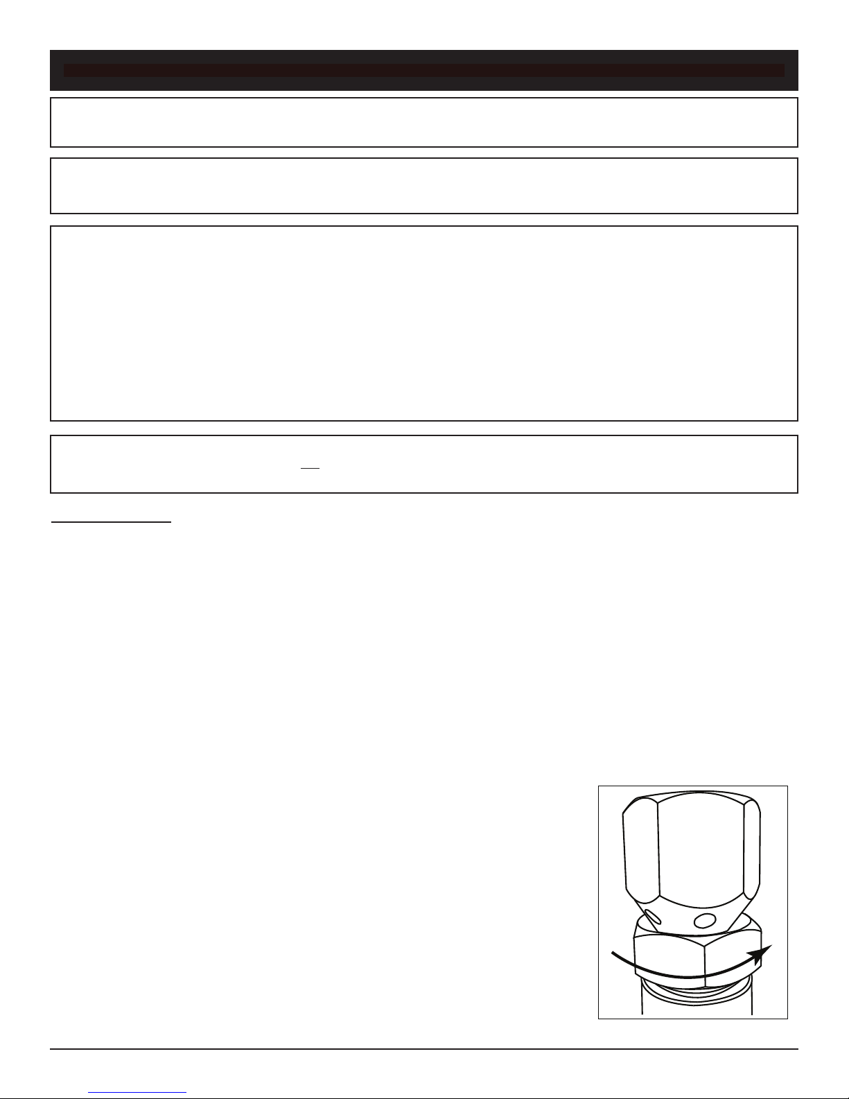
- Flame color adjustment can be made turning the air shutter nut under the burner pan.
It is recommended that the nut be opened until the gas/air mixture makes a rushing
sound (like a blow torch); then slowly closed until the rushing sound diminishes. A desirable ame is bright yellow with little or no brown at the tips. Too yellow ame can create
excessive sooting (See g. 11).
Skytech Fire Pits
Fig. 11 Air shutter adjustment
REV. 1-6-12 Page 8
Page 10
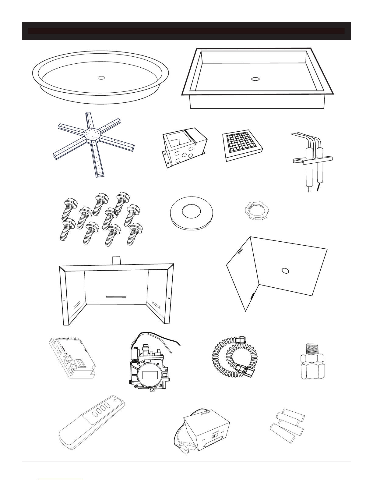
REPLACEMENT PARTS
ON
OFF
HI
LO W
SKYTECH
SKYTECH
SKYTECH
SKYTECH
1
3
7
8
2
5
6
4
9
14
Skytech Fire Pits
12
18
15
19
13
16
17
20
REV. 1-6-12 Page 9
Page 11

REPLACEMENT PARTS
Item
1 25-inch Round Stainless Burner Pan
1 19-inch Round Stainless Burner Pan
2 26-inch Square Stainless Burner Pan
2 20-inch Square Stainless Burner Pan
3 Spoke Burner (used on 19” & 20” Fire Pits)
3 Spoke Burner (used on 25” & 26” Fire Pits)
4 Ignition Hood
5 Stainless Screen Cover for Ignition Hood
6 3-probe Ignitor Assembly (AF-5000DSI3P03)
7 #10-24 x 1/2” Stainless Thread Cutting Screw
8 7/8” Flat Washer/Spacer
9 1/2” NPT Conduit Lock Nut
10 1 x 2 1/4” Blank Cover Plate (not shown)
11 DSI Valve Box Assembly (not shown)
12 Stainless DSI Fire Pit Valve Box Only
13 Stainless DSI Fire Pit Valve Box Cover Only
14 Control Module AF-5000MOD-1 (Inside valve box)
15 AF-4025 DSI Gas Valve - 5.0”WC (Natural Gas)
16 1/2” Flex Gas Line (24-inch Length)
17 Air Shutter Orice NG #13 (Used on 25/26” Fire Pits)
17 Air Shutter Orice LP #30 (Used on 25/26”: Fire Pits)
17 Air Shutter Orice NG #22 (Used on 19/20” Fire Pits)
17 Air Shutter Orice LP #35 (Used on 19/20” Fire Pits)
18 RCAF-3 Transmitter ON/OFF/HI/LO with 12V Battery
19 AF-4000BP12 (Battery Pack & 12-foot Wire Harness)
20 AA Batteries (Used in Battery Pack)
Description
Qty.
Part Number
1 ST3-100-1025
1 ST3-100-1024
1 ST3-100-1028
1 ST3-100-1029
1 ST3-100-1022
1 ST3-100-1023
1 ST3-100-1026
1 ST3-100-1027
1 ST3-091-1007
10 ST3-113-1028
1 ST3-113-1026
1 ST3-113-1027
1 ST3-100-1030
1 ST2-010-1010
1 ST3-100-1020
1 ST3-100-1021
1 ST3-030-1039
1 ST2-080-1025
1 ST3-094-1001
1 ST3-092-1006
1 ST2-092-1005
1 ST3-092-1004
1 ST2-092-1000
1 ST1-020-1034
1 ST3-040-1017
4 ST1-060-1001
Skytech Fire Pits
REV. 1-6-12 Page 10
Page 12

FIRE PIT MAINTENANCE
1. The Fire Pit should be inspected and cleaned before initial use at least annually by a qualied eld service person.
2. Any component that is found faulty must be replaced with an approved component.
3. Any tampering or modifying with the Fire Pit is dangerous and voids all warranties.
4. During winter months in cold climates and various seasons operation the Fire Pit may be affected by weather condi
tions. It is recommended to use a ventilated cover overtop of your Fire Pit to protect it from humid/rainy weather condi
tions when not in use. Heavy rains/downpours could affect the Fire Pit operation if not covered; if this occurs ensure
you allow the Fire Pit time to dry out before attempting to operate. NOTE: If a combustible type cover is used over the
Fire Pit when not in use be sure to remove it before operation to prevent a severe safety hazard.
5. Carbon (soot) may build up on the surface of logs (if installed) during heavy use. Sooting may also occur periodically
on the screen of the ignitor hood. To clean, brush off with a dry bristle brush or cloth. Keep soot away from clothing or
furniture.
6. Over time stainless steel parts discolor when heated, usually a golden or brown hue. This discoloration is normal and
does not affect the performance of the appliance.
TROUBLE SHOOTING
FAULT CODES
The AF-5000MOD-1 control module has built-in error detection for several common operating fault conditions. When the
control module detects an error, it will emit a series of beeps. The beeping pattern will help to determine the cause of the
operating fault.
Ignition Safety (Protection for Ignition system):
Error Code: One beep every one second.
Description of Fault: Warn users if the pilot is not successfully ignited in 15 seconds.
How to Clear: Press OFF then ON buttons to re-attempt ignition.
What to Check:
1. Ensure gas supply is turned on.
2. Ensure that the gas line is purged of air. Air is common in the gas line if the appliance has just been installed, has
been disconnected then re-connected to the gas line, or if the appliance has been unused for an extended period
of time.
3. Ensure there is no blockage in the gas line.
4. Make sure that the ame sensor electrode is clean. Soot buildup will insulate the electrode and will not allow for
proper ame sensing.
5. Ensure orange/white leads from module are plugged into the “PILOT” connection on the valve body.
6. Ensure green/white leads from module are plugged into the “MAIN” connection on the valve body.
7. Verify lead from igniter on electrode assembly is connected to the “I” terminal on the module.
8. Verify lead from ame sensor on electrode assembly is connected to the “S” terminal on the module.
9. Verify that the black ground lead from the module is connected to a proper ground on the appliance.
Sensor Safety (Protection for Flame sensor):
Error Code: 4 Beeps every one second (Constant beeping)
Description of Fault: Warn users that the ame sensor detects a ame already present when ignition sequence is initiated.
This fault will also occur if the ame sensor is shorted to ground.
How to Clear: Press OFF then ON buttons to re-attempt normal ignition.
What to Check:
1. Check if ame is actually present when valve is turned OFF (if so, replace valve).
2. Ensure that the ame sensor electrode is not touching the burner or another metal surface.
3. Check if the ame sensor wiring is worn, frayed, or otherwise damaged.
4. If 3-probe ignitor is exposed to excessive moisture/water it will need 24-48 hours to dry out.
6. Replace electrode assembly.
7. Replace module.
Skytech Fire Pits
REV. 1-6-12 Page 11
Page 13
Thermal Safety (Overheat Protection):
Error Code: 4 Beeps every 2 seconds.
Description of Fault: Warn users that the modules internal temperature exceeds 170°F.
How to Clear: Module’s internal temperature must cool to below 160°F and then press ON button.
What to Check:
1. Ensure that there is proper ventilation to the control module.
2. Is module located in unapproved location, too close to burner?
3. Move to cooler location.
Wireless Remote Transmitter Will Not Operate Appliance
1. Make sure that the transmitter is within the 25-foot operational range of the control module.
2. Ensure batteries in transmitter are fully charged and properly installed.
3. If using the battery pack, ensure batteries are fully charged and properly installed. Also, make sure that the bat
tery pack’s 4-pin connector is securely connected to the battery pack and control module.
4. If using optional AC adapter, ensure that the AC adapter leads are securely attached to “POWER” connection on
the control module. Also, ensure that the AC adapter is connected to a live 120VAC power source.
5. Ensure “Remote/Off” switch on control module is set to “Remote”.
6. Ensure the control module has learned the transmitter’s security code (learning section pg. 7).
7. Make sure that the remote transmitter is not placed/mounted to a metal surface, which will reduce the operating
range.
8. Make sure that there is not a large metal obstruction between the remote transmitter and the control module.
Igniter Electrode Sparks Frequently During Operation
1. The control module will generate a spark at the igniter electrode if the system is in the ON position, but does not
sense a ame.
2. Make sure that the ame sensor electrode is clean. Soot buildup will insulate the electrode and will not allow for
proper ame sensing.
3. Make sure that wind does not blow the ame off of the ame sensor. The sensor hood and the appliance media
(rocks, glass, etc.) provides shielding from the wind. Ensure that the sensor hood and appliance media is properly
positioned per the appliance instructions. If wind is too strong, and the ame will not maintain contact with the
ame sensor, the appliance should not be operated.
Flame Modulation Will Not Work or Works Backwards
1. Ensure that the black and red leads from the battery pack are securely connected to the red and black leads from
the Hi/Lo latching solenoid located on the valve body (red to red and black to black).
2. Verify that the selector switch on the battery pack is set to LATCHING SOLENOID only.
3. Check functionality with all transmitters to determine if there is an issue with the main control system or an
individual transmitter. If the issue is with an individual transmitter, make sure that the batteries in both the transmit
ter and battery pack are installed properly and fully charged.
Fig. 12 Wiring Diagram
Skytech Fire Pits
REV. 1-6-12 Page 12
Page 14
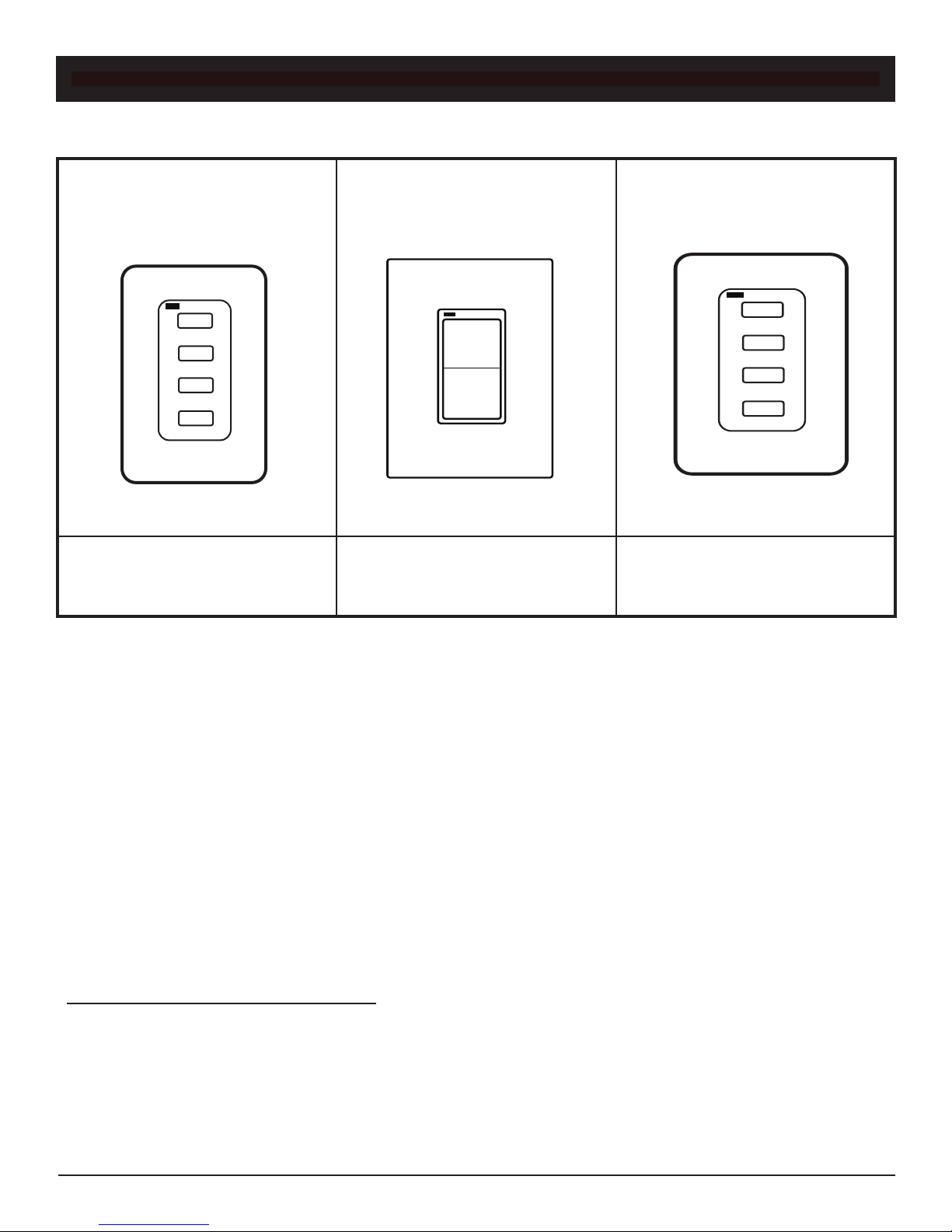
OPTIONAL ACCESSORIES
ON
OFF
HI
LO
30MIN.
60 MIN.
120 MIN.
OFF
The following accessories are available from your local Skytech dealer/distributor. Each accessory comes with a separate
installation manual. Read each instruction thoroughly before installing.
MODEL: 1322WT
Wireless wall switch with ON/OFF/
HI/LO
MODEL: SSB19DSI LP
Natural Gas to LP Gas Conversion Kit
used with 19/20-inch re pits
MODEL: 1001-DTX
Wireless wall switch with ON/OFF
ONLY
MODEL: SSB25DSI LP
Natural Gas to LP Gas Conversion Kit
used with 25/26-inch re pits
MODEL: TMR-AF1TX
4-Button Timer with 30/60/120/OFF
Minutes
MODEL: AF-4000ADP24
120 Volt adapter converts to 6DCV to
eliminate batteries with re pits
NOTE: THE MANUFACTURER IS NOT RESPONSIBLE FOR ANY RADIO OR TV INTERFER ENCE CAUSED BY
UNAUTHORIZED MODIFICATIONS TO THIS EQUIPMENT. SUCH MODIFICATIONS COULD VOID THE USER’S
AUTHORITY TO OPERATE THE EQUIPMENT.
FOR TECHNICAL SERVICE CONTACT:
Skytech Fire Pits
FCC REQUIREMENTS
Skytech
9230 Conservation Way
Fort Wayne, IN 46809
1- (888) 672-8929
Fax (260) 459-1592
WEB SITE: www.skytechsystem.com
REV. 1-6-12 Page 13
Page 15

WARRANTY
The warranty for the Skytech Outdoor Fire Pits is (5) ve years on only the Stainless Steel Components for the original owner, and this warranty is not transferable. Should any of the Stainless Steel
components fail because of the workmanship or material for the original date of purchase. Skytech
will repair or, at Skytech option, replace the defective components.
Skytech warranties all non-stainless steel components for one year to the original owner in
commericial applications. This would be the gas valve, electric module and all other components.
This warranty is covering component failure for workmanship or material for the original owner.
This warranty does not cover claims, which do not involve defective workmanship or materials.
Damage to the Skytech Outdoor Fire Pits caused by accident, misuse, abuse, or installation error,
whether performed by a contractor, Service Company, or owner, is not covered by this warranty.
Modication of the Skytech product will void this warranty.
IN NO EVENT SHALL SKYTECH BY LIABLE FOR INCIDENTAL AND CONSEQUENTIAL INCLUDING THE IMPLIED WARRANTIES OF MERCHANTABILITY AND FITNESS, ARE LIMITED TO
THE DURATION OF THIS WRITTEN WARRANTY. THIS WARRANTY SUPERSEDES ALL OTHER
ORAL OR WRITTEN WARRANTIES.
Some states do not allow the exclusion or limitation of incidental and consequential damages or
limitation on how long and implied warranty lasts, so the above limitation may not apply to you. This
warranty gives you specic rights and you may have other rights, which vary form state, province,
and nation.
Warranty claim process will start with all of this information. Skytech will reserve the right to
physically inspect the product for defects, by authorized representatives.
Skytech Fire Pits
REV. 1-6-12 Page 14
 Loading...