

Page 1
!
Electronic
Fan Speed Control
HI
MH
ML
LO
OFF
FAN
SPEED
TEST
FAN TURNS ON TO
SELECTED SPEED
7 MINUTES AFTER MAIN
FLAME IS TURNED ON
FAN TURNS OFF
12 MINUTES AFTER MAIN
FLAME IS TURNED OFF
TEST WILL TURN FAN
ON HIGH AS LONG AS
BUTTON IS PRESSED
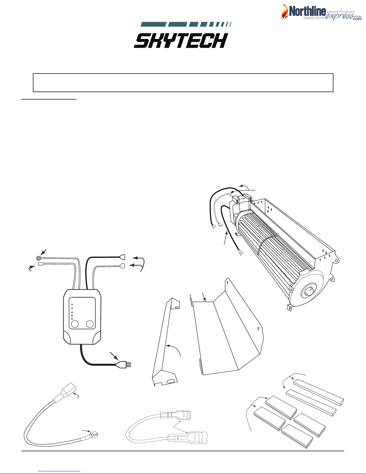
2 - 1/4” Female
Connectors
1 - 1/4” Female
Connector
1- 1/4” Ring Connector
1- Polorized Plug
1 - 3/16” Piggyback Connector
1 - 1/4” Male Connector
!
Model: FK-165-ESC Fan Kit
1/4” Female Connectors
F-165
Ground
(greeen)
Power Wires
Air Deector
Mounting
Bracket
Magnetic Strips
Foam Strips
INSTALLATION AND OPERATION INSTRUCTIONS
IF YOU CANNOT READ OR UNDERSTAND THESE INSTALLATION INSTRUCTIONS
DO NOT ATTEMPT TO INSTALL OR OPERATE
INTRODUCTION
The FK-165-ESC Fan Kit has been designed as a retrot or new fan kit to circulate room air through many hearth products
in the industry. The FK-165-ESC operates on 120VAC, 60Hz power. The fan dimensions are 12-3/4” W x 4” H x 3-1/2” D.
Power must be provided through an approved factory installed junction box from the hearth product’s manufacturer.
A speed control (FK-ESC) is provided with the Fan Kit System to adjust the air output. The speed control will turn ON the
fan automatically 7-minutes after the main ame has been turned ON and turn the fan OFF 12-minutes after the main
ame has been turn OFF. There are four speeds, Hi, Medium Hi, Medium Lo, Lo and OFF. You can manually adjust the
speed by pressing the FAN SPEED button on the FK-ESC. The FK-ESC will remember the last setting used and remain
on that setting until manually changed.
Compare the contents of your package with the gure drawings below.
1. F-165-1 Fan with two leads and a ground wire
2. FK-ESC (speed control)
3. Air Deector and Mounting Bracket
4. Jumper Wire (used for IPI valves only)
5. Jumper Wire (used to jump power strip when applicable)
6. (2) Magnetic and (2) Foam Strips
7. (6) Phillips Sheet Metal Screws (not shown)
1
2
4
Skytech FK-165-ESC
NorthlineExpress.com
NorthlineExpress.com
5
3
www.NorthlineExpress.com
www.NorthlineExpress.com
6
REV 4-10-12 Page 1 of 5
Toll-Free 1-866-667-8454
Toll-Free 1-866-667-8454
Page 2
PRECAUTIONS
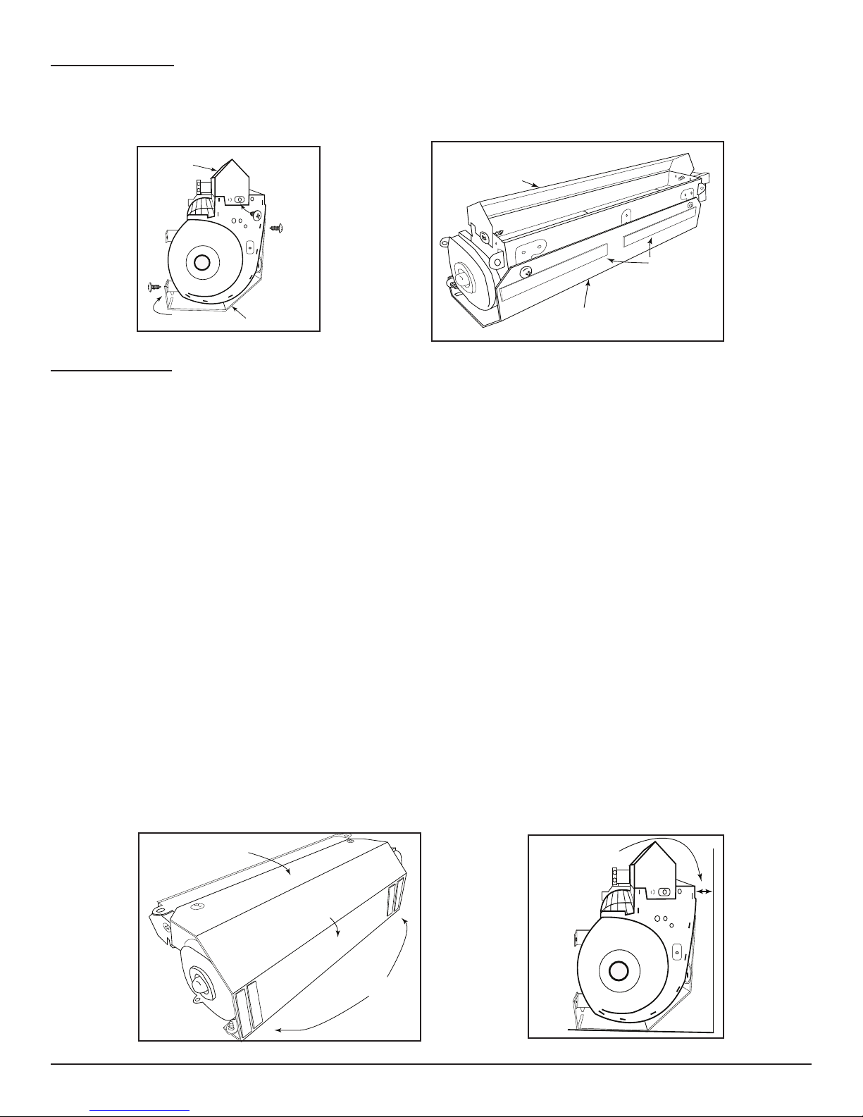
Mounting Bracket
Bend Tab
Air Deector
Air Deector
Mounting Bracket
Foam Strips
Mounting Bracket
Bottom of Mounting
Bracket
Magnetic Strips
1/8” - 1/4” Spacing
From Back Wall
Please read all the instructions before proceeding with installation. NOTE: Not all parts included with fan may be
necessary for installation.
CAUTION: A qualied electrician should complete all wiring. Install following all local codes and in compliance with the
National Electric Code ANSI/AFPA NO. 70 or CSA C22.1 for all of North America.
Fig. 1
Fig. 2
INSTALLATION
NOTE: Novus appliances do not require the use of the air deector.
WARNING: Turn electrical power OFF at the circuit breaker before beginning this installation.
1. Unplug the old fan system (if applicable) and remove it from the appliance. In some cases the existing mounting
bracket may be used. If not use the mounting bracket supplied with this fan kit.
2. Mount the air deector on the F-165-1 fan. See Figure #1. The deector sits on top of the fan as shown and
secures to the middle hole of the fan on each side. Note: Some installations may not require air deector.
3. If using the mounting bracket supplied with the FK-165-1 bend the tabs as shown in Figure #1. Note: In some
installations you may use the existing mounting bracket from the appliance. Secure the mounting bracket for the
fan in four places using the supplied sheet metal screws mating to the aligned holes on the fan housing.
4. Peel the protective covering from the foam strips and place them to the mounting bracket as shown in Figure #2.
5. Cut the magnets in half using tin snips as shown on front page (part #5). Peel the protective coating from the
magnets place them on the bottom of the
two of the magnets to secure the FK-ESC to the base of the appliance.
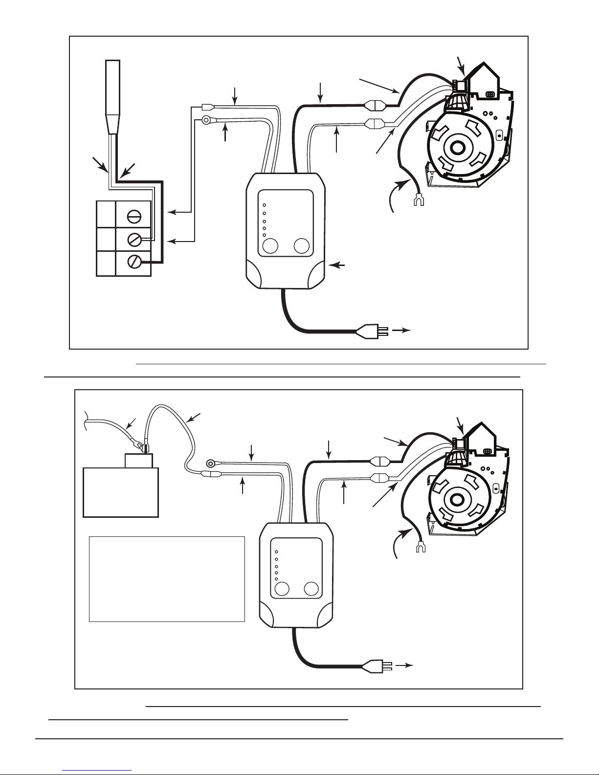
6. Attach the FK-ESC wires to the F-165-1 fan as shown in the wiring diagram (Fig.5).
7. Install the new F-165-1 fan housing in the rear of the appliance where the previous fan was installed.
8. Pull the fan housing slightly away from the back metal wall (1/8’’ to 1/4’’) of the appliance. The magnetic feet will
hold the housing in place. (See Figure #1)
9. Attach the F-165-1 fan ground (green) wire to an accessible ground source.
10. Plug the FK-ESC into an approved electrical junction box and lay inside appliance accessible for operation.
11. If installing this kit into an appliance with a Millivolt valve system use Figure #5. If installing this kit into an IPI
electronic system use Figure #6.
mounting bracket as shown in gure #3. OPTION: You can use
Skytech FK-165-ESC
NorthlineExpress.com
NorthlineExpress.com
Fig. 3
www.NorthlineExpress.com
www.NorthlineExpress.com
Fig. 4
REV 4-10-12 Page 2 of 5
Toll-Free 1-866-667-8454
Toll-Free 1-866-667-8454
Page 3
Electronic
Fan Speed Control
HI
MH
ML
LO
OFF
FAN
SPEED
TEST
FAN TURNS ON TO
SELECTED SPEED
7 MINUTES AFTER MAIN
FLAME IS TURNED ON
FAN TURNS OFF
12 MINUTES AFTER MAIN
FLAME IS TURNED OFF
TEST WILL TURN FAN
ON HIGH AS LONG AS
BUTTON IS PRESSED
Fan Hot (Black)
Fan Netural
(white)
120VAC
Power
Source
TH
TP
TH
TP
Millivolt Valve
Terminal
Thermopile
White
Red
F-165 Fan
FK-ESC
Ground (green)
Sense -
(black)
Sense +
(red)
Fig. 5 Millivolt Wiring Diagram
Electronic
Fan Speed Control
HI
MH
ML
LO
OFF
FAN
SPEED
TEST
FAN TURNS ON TO
SELECTED SPEED
7 MINUTES AFTER MAIN
FLAME IS TURNED ON
FAN TURNS OFF
12 MINUTES AFTER MAIN
FLAME IS TURNED OFF
TEST WILL TURN FAN
ON HIGH AS LONG AS
BUTTON IS PRESSED
Fan Hot
(Black)
Fan Netural
(white)
120VAC
Power
Source
Sense -
(black)
Sense +
(red)
Dexen
or SIT IPI
Valves
Jumper Wire
(red)
Disconnect the 3/16” connector
from main coil of gas valve. Place
red jumper with piggyback
connector to valve and reconnect
the main coil wire removed from
valve to piggyback connector.
F-165 Fan
Ground (green)
Main Coil Wire
of Gas Valve
WIRING NOTES: This is a polarity sensitive system. Ensure you wire it exactly as shown in the diagram
above. Thermopile wires must also be located with Red at TH/TP and White at TP on the gas valve.
WIRING NOTES: When wiring an IPI system the Sense - (black) wire must be secure to a ground on
the gas valve or to metal on the appliance for proper operation.
Fig. 6 IPI Wiring Diagram
Skytech FK-165-ESC
NorthlineExpress.com
NorthlineExpress.com
www.NorthlineExpress.com
www.NorthlineExpress.com
REV 4-10-12 Page 3 of 5
Toll-Free 1-866-667-8454
Toll-Free 1-866-667-8454
Page 4
!
!
NEUTRAL
HOT
5 4 3 2 1
5 4 3 2 1
FAN
REM/AUX
TRANS
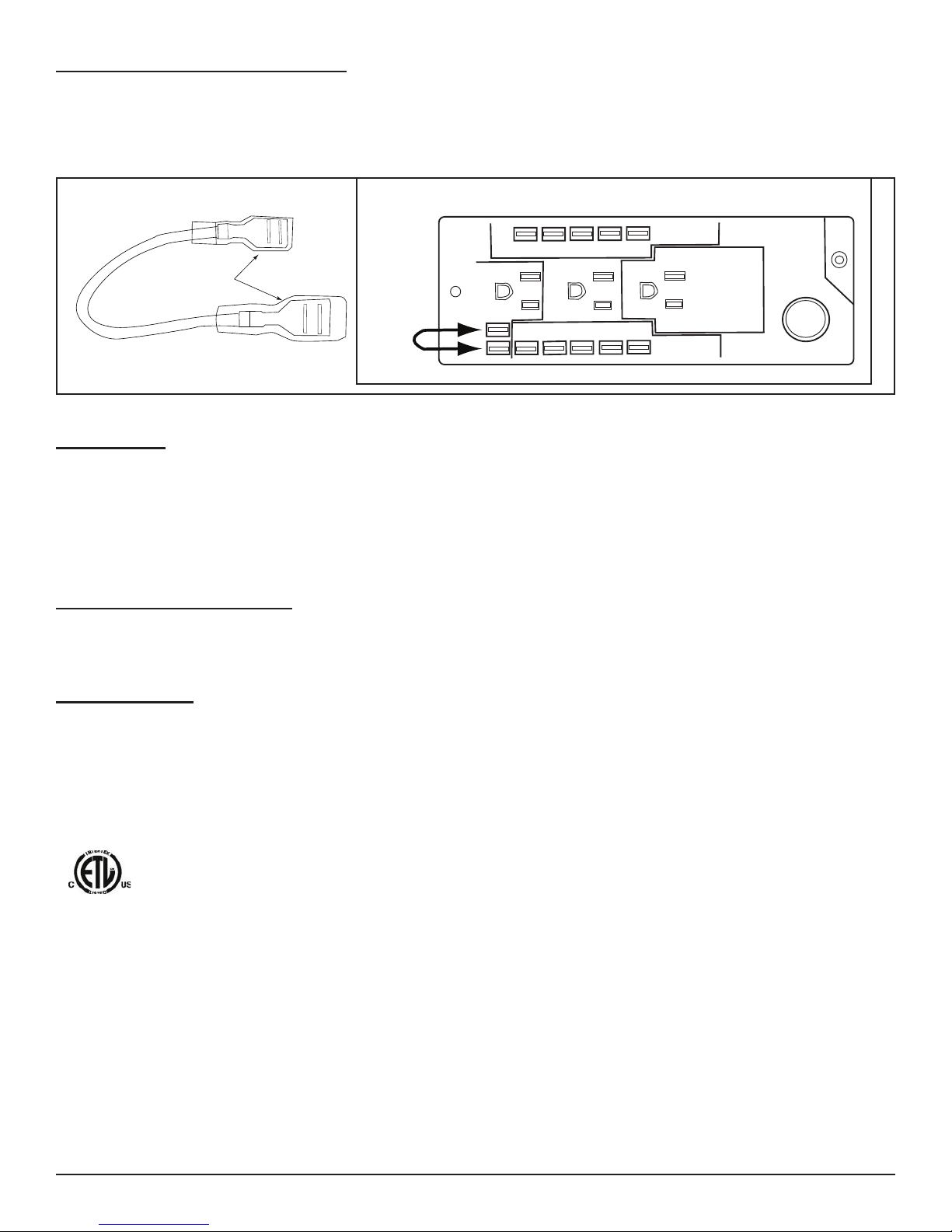
Jumper
Wire
Power Strip
1/4” Female Connectors
!
POWER SOURCE INFORMATION
When plugging in the FK-ESC into a 120VAC power source, some replaces use a standard metal junction box and other
replaces may use a power strip. If a power strip is used (as shown below in gure 4) and no power is found in the FAN
outlet use the red jumper wire with the 1/4” connectors and attach as shown below. With the jumper installed the FAN
outlet will provide the power necessary to operate the FK165-1 system.
Fig. 4 Power strip jumper connection
OPERATION
The speed control will turn ON the fan automatically 7 minutes after the main ame has been turned ON and turn the fan
OFF 12 minutes after the main ame has been turn OFF. There are four speeds, Hi, Medium Hi, Medium Lo, Lo and OFF.
Manually adjust fan speed by pressing the FAN SPEED button on the FK-ESC.
To check the fan for proper wiring press the TEST button. This is a manual override that will operate the fan on HI as long
as the button is depressed. The FK-ESC will remember the last setting used and remain on that setting until changed.
OPTIONAL ACCESSORIES
16 SPT 2 – Optional 16-inch extension cord to plug into junction box for greater mobility of the FK-ESC.
MAINTENANCE
Cleaning on a semi-annual basis is required to keep the warranty in place. Dust or dirt must be removed from the fan
blades, air inlets and blower outlet for the fan kit to maintain the efciency of the system. Carefully use a vacuum with a
brush to remove any dust. If unable to reach fan with a vacuum remove the fan from the appliance for easier cleaning.
Recognized component according to UL 1004-1 and UL 1004-3 and CSA C22.2 No. 100-04 and CSA C22.2
No 77-95 R2004
Skytech FK-165-ESC
NorthlineExpress.com
NorthlineExpress.com
www.NorthlineExpress.com
www.NorthlineExpress.com
REV 4-10-12 Page 4 of 5
Toll-Free 1-866-667-8454
Toll-Free 1-866-667-8454
Page 5

TWO YEAR LIMITED WARRANTY
SKYTECH II warrants this fan system for two years or 24 months from the date of purchase to the
original owner. This warranty is NOT transferable to another person. Should any part fail because
of defective workmanship or material from the original date of purchase SKYTECH II will repair or
replace the part at SKYTECH II option.
Damage to the Fan system caused by accident, misuse, abuse, or installation error, whether by a
contractor, service company, or owner is not covered by this warranty. Modication of the Fan System
will void the warranty.
The owner must provide a bill of sale, to verify purchase date and establish warranty period.
SKYTECH II is not responsible for: Travel expenses, Diagnostic costs, and Service labor to repair the
defective Fan system. Freight charges will not be covered on warranty parts or Fan systems.
This warranty does not cover claims, which do not involve defective workmanship or materials.
IN NO EVENT SHALL SKYTECH II BE LIABLE FOR INCIDENTAL AND CONSEQUENTIAL
OCCURRENCES, INCLUDING THE IMPLIED WARRANTIES OR MERCHANTABILITY AND FITNESS, ARE LIMITED TO THE DURATION OF THE THIS WRITTEN WARRANTY. THIS WARRANTY
SUPERSEDES ALL OTHER ORAL OR WRITTEN WARRANTIES.
Some states do not allow the exclusion or limitation of incidental and consequential damages or
limitation on how long an implied warranty lasts, so the above limitation may not apply to you. This
warranty gives you specic rights and you may have other rights, which vary from state, province, and
nation.
Warranty claims process will start with all information; SKYTECH II will reserve the right to physically
inspect the product for defects, by authorized representatives.
For Technical Questions Call:
Skytech Products Group
9230 Conversation Way
Ft. Wayne, IN 46809
1-(888) 672-8929
www.skytechsystem.com
Skytech FK-165-ESC
NorthlineExpress.com
NorthlineExpress.com
www.NorthlineExpress.com
www.NorthlineExpress.com
REV 4-10-12 Page 5 of 5
Toll-Free 1-866-667-8454
Toll-Free 1-866-667-8454
 Loading...