

Page 1
Model: 5320P
INSTALLATION AND OPERATION INSTRUCTIONS
IF YOU CANNOT READ OR UNDERSTAND THESE INSTALLATION INSTRUCTIONS DO
NOT ATTEMPT TO INSTALL OR OPERATE
NOTE: This product is designed for use with an attended hearth appliance or re feature. Adults must be present when
the Control System is operating. DO NOT program or thermostatically set this Control to operate a hearth appliance or re
feature when Adults are not physically present. Furthermore, DO NOT leave the hearth appliance or re feature burning
unattended; it may cause damage or serious injury. If an Adult is going to be away from the hearth appliance or re
feature for any length of time, then the handheld/wall mount, receiver/control module and application should be in the
“OFF” position.
INTRODUCTION
This remote control system was developed to provide a safe, reliable, and user-friendly remote control system for gas
heating appliances. The system can be operated thermostatically, manually or with the built-in factory program inside the
transmitter. The built-in program has two segments, a weekdays and a weekend segment. The factory presets are time
periods for each day. SEE PROGRAM SEQUENCE BELOW. Custom programming may be achieved after the initial
setup has been performed.
This system operates on radio frequencies (RF) within a 20-foot range using non-directional signals. The system
operates one of 1,048,576 security codes that are programmed into the transmitter at the factory; the remote receiver’s
code must be matched to that of the transmitter prior to initial use.
Built-in Factory Programs
Weekdays - Mon. Tues. Wed.Thurs. Fri.
MORN
Program 1 (P1)
Weekends - Sat. Sun.
Program 1 (P1)
Table 1 Factory program.
5:00AM
72°
MORN
6:00AM
72°
9:00AM
10:00AM
Program 2 (P2)
Program 2 (P2)
4:00PM
5:00PM
DAY
10:00PM
72°
DAY
10:00PM
72°
Skytech: 5320P
REV. 8-11-20 Page 1
Page 2
MODE
SET
PROG
1
1
2
2
3
4
3
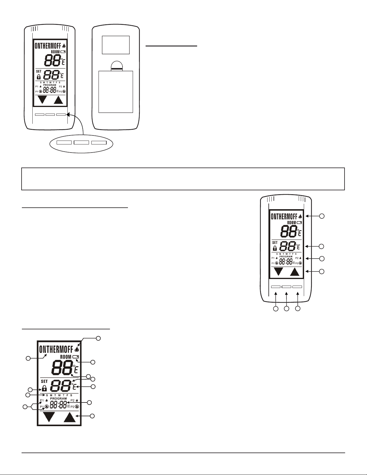
TRANSMITTER
MODE
BATTERY
COMPARTMENT
BACK
FRONT
SET
PROG
PROG
MODE
SET
The transmitter operates on (4) AAA 1.5V batteries that are included.
Install the batteries supplied with the unit into the battery compartment. It
is recommended that ALKALINE batteries always be used for this product.
Be sure the batteries are installed with the (+) and (-) ends facing the
correct direction.
When you start up the remote, if a low battery signal appears or if the LCD
screen does not illuminate when you touch it, check battery position and if
the batteries are fully charged.
Fig. 1 Transmitter.
Review COMMUNICATION SAFETY under TRANSMITTER section and THERMO SAFETY under
REMOTE RECEIVER section. These signal and temperature safety features shut down the replace system
when a potentially unsafe condition exists.
KEY AND TOUCHSCREEN SETTINGS
1. MODE - Switches the appliance On/Thermo/Off.
2. PROGRAM - Turns ON and OFF the program function.
3. SET - Used in different functions to conrm settings.
4. UP and DOWN - Used to change the time, set temp, and programming functions.
LCD - LIQUID COLOR DISPLAY
6
2
8
9
11
10
Fig. 3 LCD display.
Skytech: 5320P
Fig. 2 Button settings.
1. BATTERY ICON - Battery power is low. Replace Batteries in 2 - 4 weeks.
5
2. ROOM - Indicates CURRENT room temperature.
3. SET- Indicates desired SET room temperature for THERMO operation.
4. FAHRENHEIT/CELSIUS - Indicates degrees Fahrenheit or Celsius.
1
5. FLAME- Indicates burner/valve in operation.
6. MODE – Indicates operation mode of system.
3
7. UP and DOWN – These are used to adjust the Time, Set temperature, and Program
4
functions.
8. TIME and PROGRAM TIME – Indicates current time or program time setting when
editing program settings.
9. LOCK ICON - Disables the transmitter when lock is visible on the LCD screen.
10. PROGRAM ON/OFF – Indicates when Program 1 (P1) is on or off, and indicates when
7
Program 2 (P2) is on or off.
11. DAY of WEEK - Indicates current day of week, or program segment when editing
program settings.
REV. 8-11-20 Page 2
Page 3
BASIC TRANSMITTER FUNCTIONS AND INITIAL SETUP
SET
SET
SET
SET
NOTE: Touch anyplace on the screen and the back light will light up and
stay lit for 5 seconds.
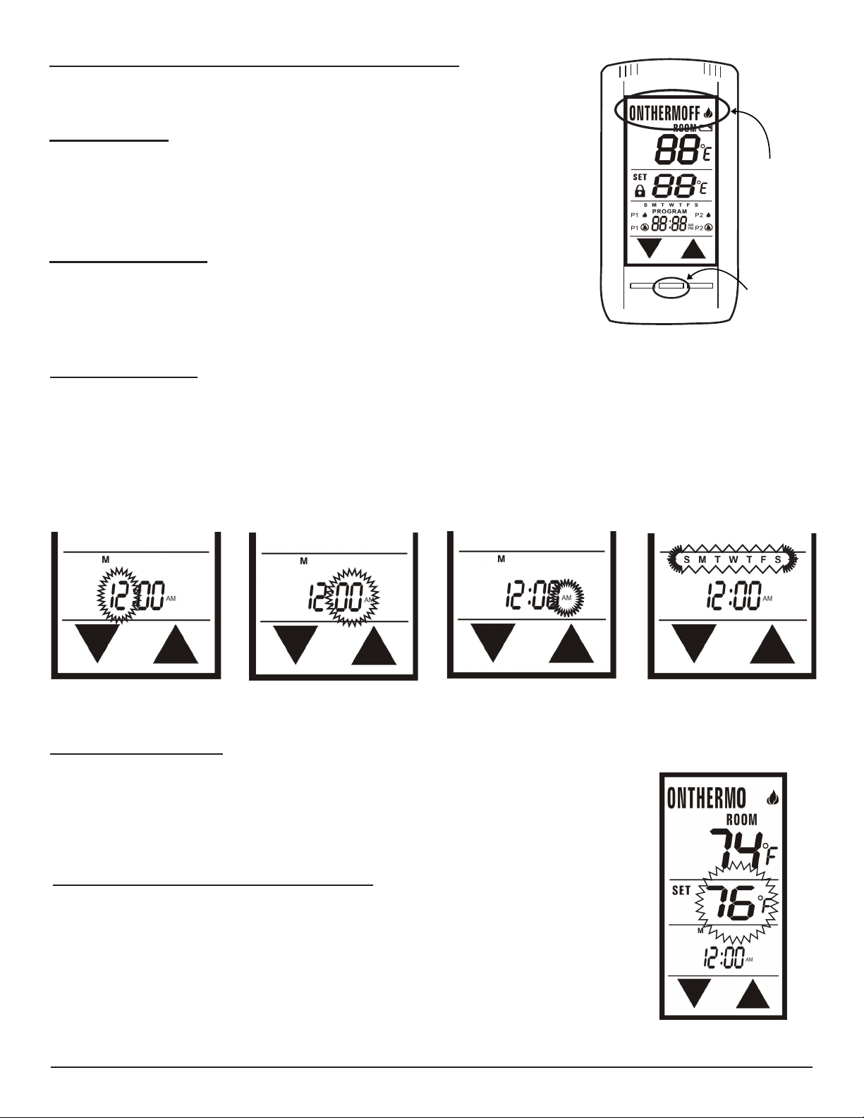
MODE FUNCTION
To select an operational mode, press the MODE (top) button or touch the MODE( top)
SECTION of the touch screen.
• ON turns the appliance manually ON; the ame icon will appear.
• THERMO sets the remote to Thermostatic mode.
• OFF turns the appliance OFF; the ame icon will disappear.
SETTING ºF / ºC SCALE
The factory setting for temperature is ºF. To change this setting to ºC, rst press and hold
the UP touch button and the DOWN touch button on the transmitter at the same time.
Follow this same procedure to change from ºC back to ºF.
PROG
MODE
SET
Fig. 4 Transmitter functions.
SETTING THE CLOCK
• Press and hold the SET button, or touch the SET (middle) section on the touch screen, for 5 seconds. The hour sec-
tion should begin to ash. (Fig. 5)
• Use the UP and DOWN touch buttons to select the hour, then press SET.
• The minutes will be ashing. Use the UP and DOWN touch buttons to select the minute, then press SET. (Fig. 6)
• The AM PM will be ashing. Use the UP and DOWN touch buttons to select one of them, then press SET. (Fig. 7)
• One of the days of the week will be ashing (above the clock). Select the correct day by pressing the UP and DOWN
touch buttons, then press SET. Your time will automatically be accepted. (Fig. 8)
Mode: Touch
Portion
Mode: Button
Fig. 5 Hours.
Fig. 6 Minutes.
Fig. 7 AM/PM. Fig. 8 Days of week.
THERMOSTAT FUNCTION
This remote control system can be thermostatically controlled when the transmitter is in
the THERMO mode (THERMO must be displayed on the screen). To set the desired room
temperature, press the MODE button to place the transmitter into thermo mode, then press
the UP or DOWN touch buttons to select the desired room temperature. The highest set
temperature is 99º F (32º C).
THERMO UPDATING FEATURE - TRANSMITTER
When in thermo mode, the transmitter reads the ROOM temperature every 2 minutes,
checks the room temperature against the SET temperature then sends a signal to the
receiver.
NOTE: The thermo feature operates the appliance whenever the room temperature varies a
certain number of degrees from the set temperature. This variation is called the “swing” or
temperature differential. This feature lets the appliance turn off and on 2º F (1º C) above or
below the set temperature of the room. This is to cushion the number of times the appliance
is turned ON and OFF. See Swing setting on page 6, Figure 19.
Skytech: 5320P
Fig. 9 Thermo mode.
REV. 8-11-20 Page 3
Page 4
PROGRAM FUNCTION
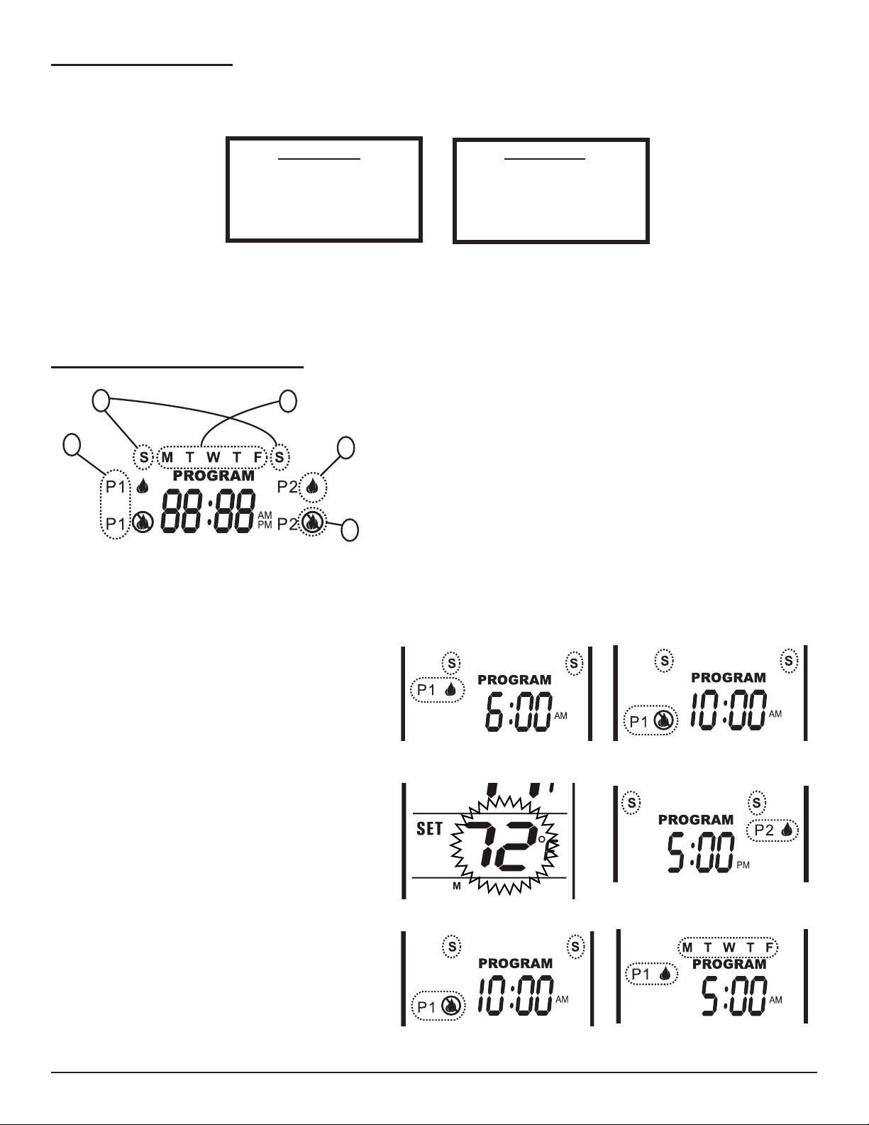
This remote has two default program segments (P1) and (P2): A weekday segment and a weekend segment. To enter
program mode, push the PROG button or touch the PROGRAM (bottom) portion of the touchscreen; the word PROGRAM
will appear above the display time to indicate program operation is active.
The factory presets are:
To turn the program function OFF, touch the PROGRAM portion on the touchscreen, or press the PROG Button at the
bottom of the transmitter. The word PROGRAM will disappear from the LCD screen.
WEEKENDS
“P1 ON” 6:00 AM at 72ºF
“P1 OFF” 10:00 AM
“P2 ON” 5:00 PM at 72ºF
“P2 OFF” 10:00 PM
WEEKDAYS
“P1 ON” 5:00 AM at 72ºF
“P1 OFF” 9:00 AM
“P2 ON” 4:00 PM at 72ºF
“P2 OFF” 10:00 PM
EDITING PROGRAM SETTINGS
2
1
Fig. 10 Edit segments.
3
1. Program Segment: (P1) Program 1 (left side of LCD screen), or
(P2)Program 2 (right side of LCD screen).
2. Weekend Segment: Saturday and Sunday.
3. Weekday Segment: Monday through Friday.
4
4. Flame ON: Flame icon shows your appliance to turn ON.
5. Flame OFF: Flame icon shows your appliance to turn OFF.
5
NOTE: P1 CAN ONLY BE SET FROM 12:00AM to 12:00PM
P2 CAN ONLY BE SET FROM 12:00PM to 12:00 AM
To edit the program settings press either the PROG button or touch the Program section of the touch screen and
hold for 5 seconds, the program section of the LCD screen will begin to ash.
• P1 ON and “S S” (Weekend Segment) should be
ashing. Select the time you want your appliance to
turn ON by using the UP and DOWN touch buttons.
Then press SET (See Fig. 11).
• P1 OFF will be ashing. Select the time you want your
appliance to turn OFF. Then press SET (See Fig.12).
• The set temperature will begin to ash. Use the UP and
DOWN touch buttons to select a temperature for P1,
then press SET (See Fig. 13).
• Now the P2 ON will begin to ash. Select the time you
want your appliance to turn ON by using the UP and
DOWN touch buttons. Then press SET. (See Fig. 14).
• P2 OFF will be ashing. Select a time you want your
appliance to turn OFF. Then press SET (See Fig. 15).
• The set temperature will begin to ash. Use the UP and
DOWN touch buttons to select a temperature for P2,
then press SET (See Fig. 11).
Fig. 11 Program ON at 6:00AM.
Fig. 13 Temperature set 72°F.
Fig. 12 Program OFF at 10:00AM.
Fig. 14 Program ON at 5:00PM.
• “MTWTF” (Weekday Segment) will replace “S S”. P1
ON will be ashing. Repeat the above steps to set the
ON and OFF times and set temperatures for weekdays.
(See Fig. 16)
Skytech: 5320P
Fig. 15 Program OFF at 10:00PM. Fig.16 Weekday segments (Mon-Fri).
REV. 8-11-20 Page 4
Page 5
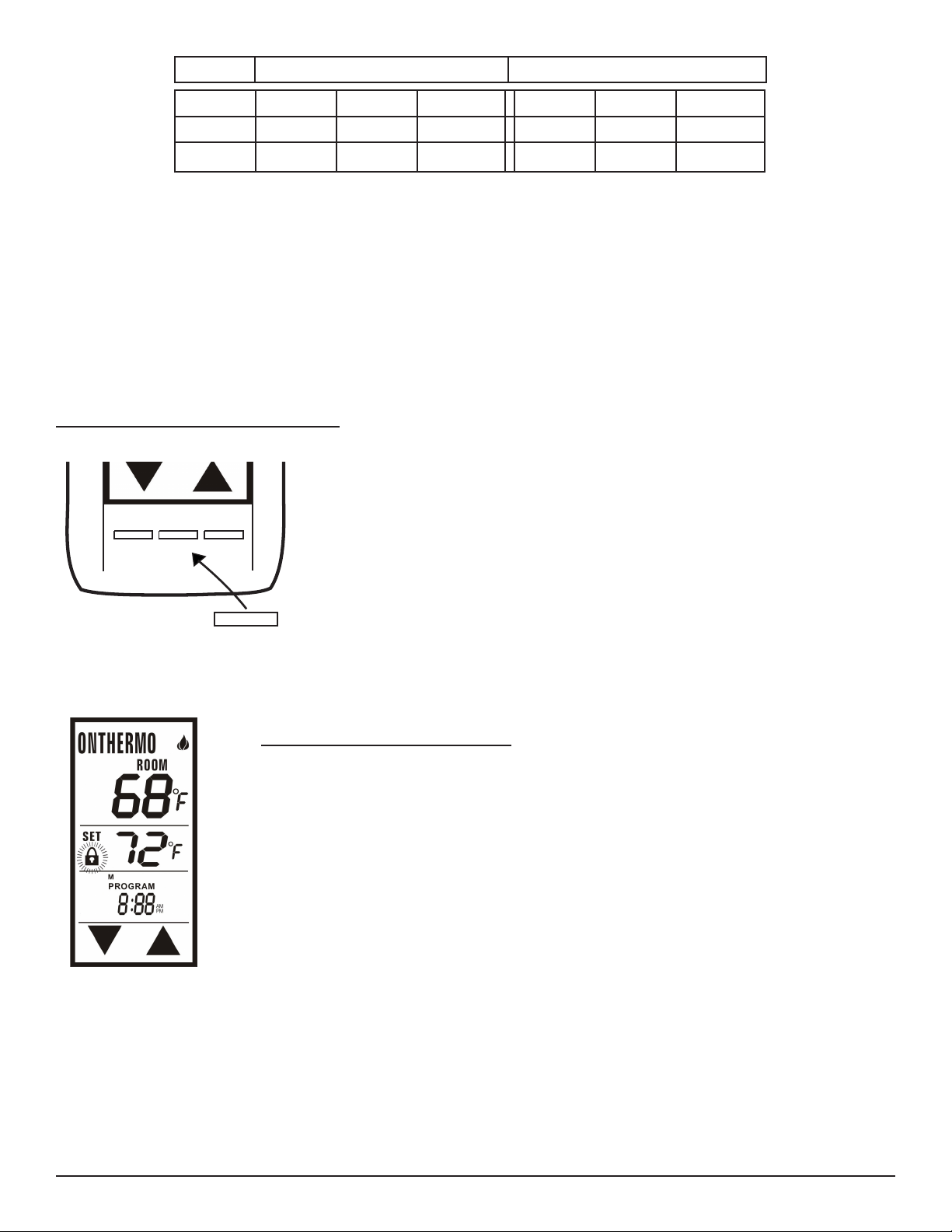
Weekends (Sat. - Sun.) Weekdays (Mon. - Fri.)
MODE
Program
ON OFF TEMP ON OFF TEMP
P1
P2
Table 2 To note custom programming
NOTE:
If you are in Manual Mode, then change to Program Mode during the Program Off segments, the transmitter will switch to
Manual OFF.
If you are in the Thermostat Mode, then change to Program Mode during the Program OFF segments, the transmitter will
switch back to Thermostat mode.
To turn the Program Mode OFF, press the PROG button. The word PROGRAM will disappear from the LCD screen
remote.
COMMUNICATION - SAFETY (C/S - TX)
This remote control has a COMMUNICATION –SAFETY function built into its software.
It provides an extra margin of safety when the Transmitter is out of the normal 20-foot
operating range of the receiver.
At all times and in all OPERATING MODES, the transmitter sends an RF signal every
MODE
PROG
SET
Fig. 17 Operating modes.
15 minutes, to the receiver, indicating that the transmitter is within the normal operating
range of 20-feet. Should the receiver NOT receive a transmitter signal every 15
minutes, the receiver will begin a 2 hour (120 minute) countdown timing function. If
during this 2-hour period, the receiver does not receive a signal from the transmitter,
the receiver will shut down the appliance being controlled by the receiver. The
receiver will then emit a series of rapid “beeps” for a period of 10 seconds. Then after
10 seconds of rapid beeping, the receiver will continue to emit a single “beep” every
4 seconds until a transmitter MODE button is pressed to reset the receiver.
Fig. 18 Childproof lock-out.
Skytech: 5320P
CHILDPROOF “LOCK-OUT” - (CP)
This remote control includes a CHILDPROOF “LOCK-OUT” feature that allows
the user to “LOCK-OUT” operation of the appliance from the TRANSMITTER.
• To activate the “LOCK-OUT” feature, press and hold the UP touch button and the SET
button together for 5 seconds. The lock icon will appear on the LCD screen.
• To disengage the “LOCK-OUT”, press and hold the UP touch button and the SET
button together for 5 seconds or more, the lock icon will disappear from the LCD
screen and the transmitter will return to its normal operating condition.
• When the Transmitter is in “LOCK-OUT” mode, programmed functions will go on without interruption; Only manual functions are prevented.
REV. 8-11-20 Page 5
Page 6
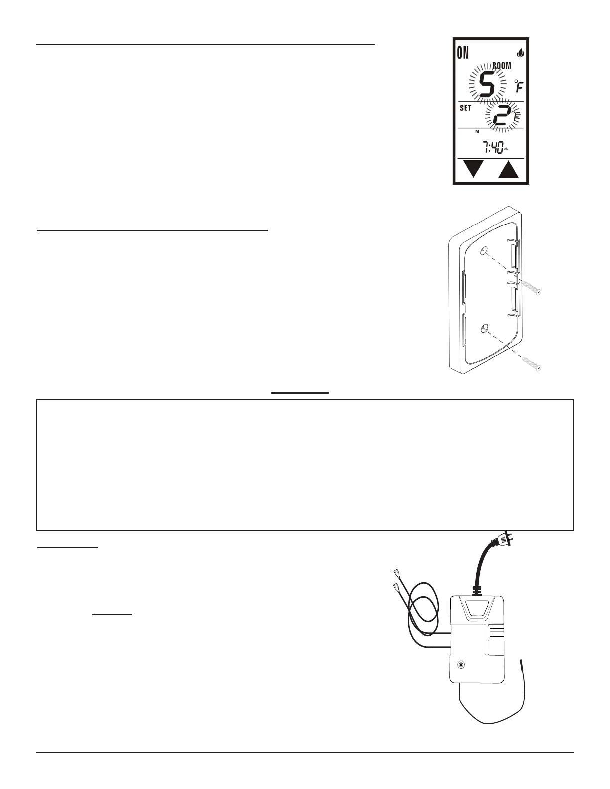
SETTING THE TEMPERATURE SWING (TEMPERATURE DIFFERENTIAL)
LEARN
The Thermo Mode on the transmitter operates the appliance whenever the room
temperature varies a certain number of degrees from the set temperature. This
variation is called the “SWING” or TEMPERATURE DIFFERENTIAL. The factory
preset swing temperature is 2º F (1º C). To change the “Swing Setting:”
• Press the SET button and the DOWN touch button simultaneously to display the
current “swing” setting in the set temp frame. The letter “S” will display in the
room temp frame on the LCD screen.
• Press the UP or DOWN touch button to adjust the “SWING” temperature (1º- 3º F)
(1º- 2º C).
• To store the “swing” setting press the SET button, and the new “swing” setting will
be automatically programmed.
TRANSMITTER WALL MOUNT BRACKET
The transmitter can be placed on a wall using the mount provided.
• Wood - Drill 1/8’’ pilot holes and install with screws provided.
• Plaster/Wallboard - Drill 1/4’’ holes, use a hammer to tap in the two plastic
anchors. Then install with the screws provided.
Fig. 19 Swing setting.
WARNING
This remote control system must be installed exactly as outlined in these instructions. Read all instructions completely
before attempting installation. Follow instructions carefully during installation. Any modications of this remote control
or any of its components will void the warranty and may pose a re hazard.
Consult gas appliance manufacturer’s instructions and wiring schematics for proper placement of all wires. All electronic
modules are to be wired to manufacturer’s specications.
The following wiring diagrams are for illustration purpose only. Follow instructions from manufacturer of gas valve and/
or electronic module for correct wiring procedures. Improper installation of electric components can cause damage to
electronic module, gas valve and remote receiver.
Fig. 20 Wall plate mounting.
RECEIVER
When plugged into a standard 110-120 VAC receptacle, the remote receiver
operates on commands from the transmitter or from the slide switch on the face
of the receiver (This switch is to be used during a power outage to operate the
appliance manually).
• ON: will manually turn ON the appliance.
• REMOTE: will allow use of handheld transmitter. If the system does not
respond to the transmitter on initial use, ensure it is plugged into a 110120VAC receptacle . If that does not work, see the LEARNING TRANSMITTER TO RECEIVER section.
• OFF: will disable the remote receiver.
• Place the slide switch in the OFF position if you will be away from
your home for an extended period of time.
The remote receiver is manufactured with a “dry contact” relay in its circuitry
that operates like an ON/OFF switch. However, no power or current passes
from the 110-120VAC input side to the wires leading from the output side of the
remote receiver.
Fig. 21 Electric receiver.
Skytech: 5320P
REV. 8-11-20 Page 6
Page 7
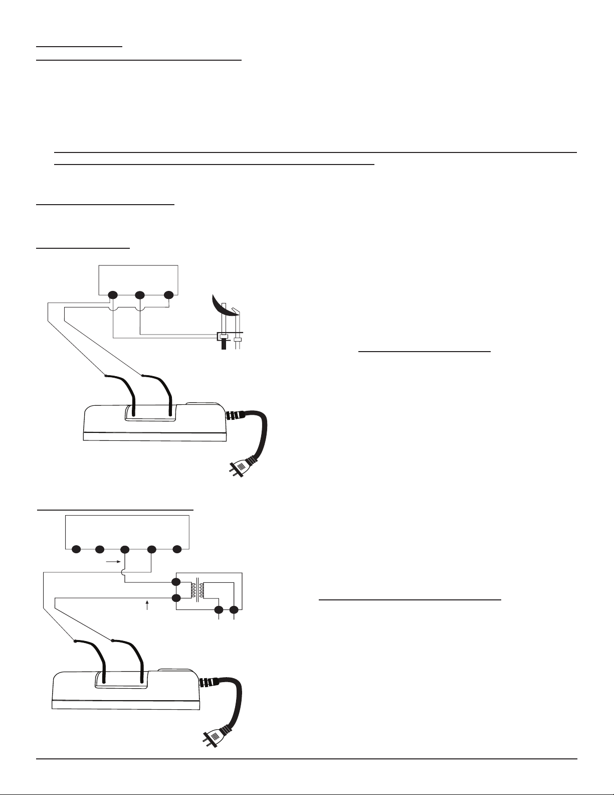
INSTALLATION
REMOTE RECEIVER
TERMINAL BLOCK
ON MILLIVOLT
GAS VALVES
TH
TP
TP
TH
THERMOPILE/
PILOT LIGHT
ELECTRONIC MODULE
TR
TH
neutral wire
24VAC
hot wire
110/24VAC
Transformer
REMOTE RECEIVER
Protection from extreme heat is very important. The remote receiver should be kept away from temperatures exceeding
130ºF. Extreme heat can cause damage, which is not covered under warranty.
• Before installation, make sure you turn the slide switch to OFF. After installation, make sure you turn the slide switch
to REMOTE.
• The remote receiver can be placed on the replace hearth or under the replace behind the control access panel.
• Use the wires attached to the remote receiver to connect to the gas valve or the electric module (piggyback
connectors have both male & female terminals for exibility).
• Be sure that the connectors do not touch each other or other bare metal surfaces; this will cause the appliance to turn
ON. The connectors may be wrapped with electrical tape to prevent this.
WIRING INSTRUCTIONS
A qualied electrician should install the remote control system.
MILLIVOLT VALVES
• Connect one wire from the remote receiver to the TH terminal
on the gas valve.
• Connect the other wire from the remote receiver to the TH/TP
terminal on the gas valve.
Fig. 22 Millivolt wiring.
ELECTRONIC SPARK IGNITIONS
Fig. 23 Electronic wiring.
MILLIVOLT SYSTEM CHECK
• Ensure that the pilot ame is lit.
• Slide the 3-position button on the remote receiver to the ON
position. The main gas ame (i.e., the re) should ignite.
• Slide the button to OFF. The main ame should extinguish
(the pilot ame will remain on).
• Slide the button to REMOTE, then press the ON button on
the transmitter to change the system to ON. The main gas
ame should ignite.
The remote control receiver can be connected, in series, to a 24VAC
transformer to the TR (transformer) terminal on the ELECTRONIC
MODULE. Connect the hot wire from the 24VAC transformer to
either of the wires on the remote receiver. Connect the other wire from
the receiver to the TH (thermostat) terminal on the
ELECTRONIC MODULE.
ELECTRONIC SPARK SYSTEM CHECK
• Slide the 3-position button on the remote receiver to the ON
position. The spark electrode should begin sparking to ignite
the pilot. After the pilot ame is lit, the main gas valve should
open and the main gas ame should ignite.
• Slide the button to OFF. The main gas ame and pilot ame
should both extinguish.
• Slide the button to REMOTE, then press the ON button on
the transmitter to change the system to ON. The spark electrode should begin sparking to ignite the pilot. After the pilot
is lit, the main gas valve should open and the main gas ame
should ignite.
Skytech: 5320P
REV. 8-11-20 Page 7
Page 8
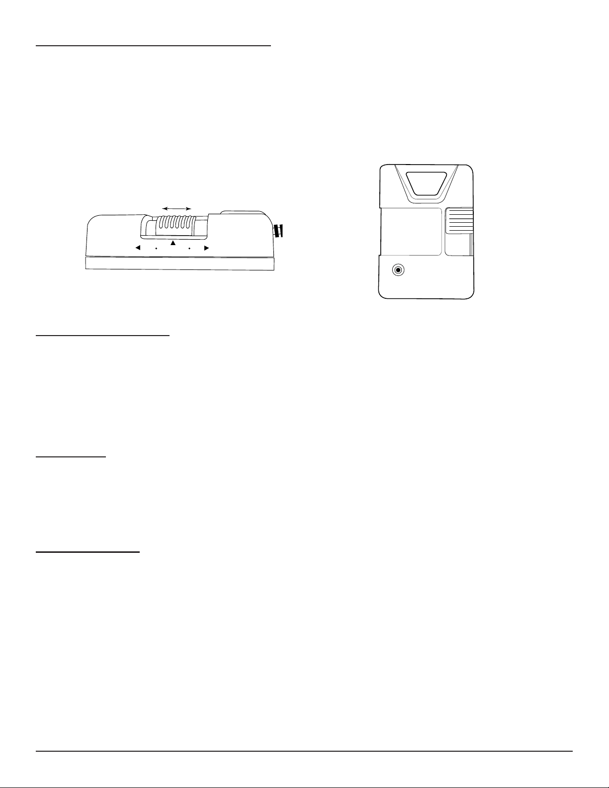
LEARNING TRANSMITTER TO RECEIVER
ON
REMOTE
OFF
Each transmitter uses a unique security code. It will be necessary to press the LEARN button on the receiver to accept
the transmitter security code upon initial use or if a replacement transmitter is purchased from your dealer or the factory.
In order for the receiver to accept the transmitter security code, be sure the slide button on the receiver is in the REMOTE
position; the receiver will not LEARN if the slide switch is in the ON or OFF position. The LEARN button in located on
the front face of the receiver; inside the small hole labeled LEARN. Press and Release the black LEARN button inside
the hole. When you release the LEARN button the receiver will emit an audible “beep”. After the receiver emits the beep
press the transmitter MODE button and release. The receiver will emit several beeps indicating that the transmitter’s code
has been accepted into the receiver.
Fig. 24 Receiver slide switch.
LEARN
Fig. 25 Learn button.
THERMO SAFETY FEATURE
If the receiver at anytime should reach 130ºF, the receiver will automatically shut down and begin to beep 3 beeps every 2
seconds. Once the temperature has dropped between 120ºF and 130ºF, the user can reactivate the appliance by
pressing the MODE button, but the beeping will continue until temperatures drop below 120ºF. This is to tell the user that
the receiver needs to be relocated to reduce temperatures.
If this situation happens, the receiver should be placed somewhere else where it will not reach temperatures in excess of
130ºF.
BATTERY LIFE
Life expectancy of the alkaline batteries in the transmitter should be at least 12 months. Check and replace all batteries:
• Annually.
• When operating range becomes reduced.
• When transmissions are not received by the remote receiver.
• If the hand held transmitter batteries measure less than 5.3 volts all (4) batteries in combination).
TROUBLE SHOOTING
If you encounter problems with your replace system, the problem may be with either the replace itself or with the remote. Review the replace manufacturer’s operation manual to make sure all connections are properly made, then check
the operation of the remote in the following manner:
• Make sure all batteries are correctly installed in the transmitter and receiver. Also check that the batteries are fully
charged.
• Check batteries in transmitter to ensure contacts are touching (+) and (-) ends of battery. Bend metal contacts in for
tighter t.
• Be sure receiver and transmitter are within 20 to 25-foot operating range.
• Keep receiver from temperatures exceeding 130º F.
• If no beeps are heard from the receiver clear codes by pressing and holding the learn button for 10 seconds, then
release.
• Check to ensure the pilot knob (on gas valve) is in the ON position.
• If receicver is beeping, refer to page 5 for COMMUNICATION SAFETY.
• If receiver is installed in a tightly enclosed metal surrounding, the operating distance will be shortened.
• Make sure the hand-held transmitter and remote receiver are communicating properly (see LEARNING
TRANSMITTER TO RECEIVER on page 8).
Skytech: 5320P
REV. 8-11-20 Page 8
Page 9

FCC REQUIREMENTS
NOTE: THE MANUFACTURER IS NOT RESPONSIBLE FOR ANY RADIO OR TV INTERFERENCE CAUSED BY UNAUTHORIZED
MODIFICATIONS TO THE EQUIPMENT. SUCH MODIFICATIONS COULD VOID THE
USER’S AUTHORITY TO OPERATE THE EQUIPMENT
Federal Communication Commission Interference Statement
This equipment has been tested and found to comply with the limits for a Class B digital device, pursuant to Part 15 of the FCC
Rules.
These limits are designed to provide reasonable protection against harmful interference in a residential installation. This
equipment generates, uses, and can radiate radio frequency energy and, if not installed and used in accordance with the
instructions, may cause harmful interference to radio communications. However, there is no guarantee that interference will not
occur in a particular installation.
If this equipment does cause harmful interference to radio or television reception, which can be determined by turning the
equipment off and on, the user is encouraged to try to correct the interference by one or more of the following measures:
• Reorient or relocate the receiving antenna.
• Increase the separation between the equipment and receiver.
• Connect the equipment into an outlet on a circuit different from that to which the receiver is connected.
• Consult the dealer or an experienced radio/TV technician for help.
This device complies with Industry Canada license - exempt RSS standard(s).
Operation is subject to the following two conditions:
(1) This device may not cause interference, and
(2) This device must accept any interference, including interference that may cause undesired operation of the device.
Cet appareil est conforme aux normes RSS exemptes de licence d’Industrie Canada.
Le fonctionnement est soumis aux deux conditions suivantes:
(1) Cet appareil ne doit pas causer d’interférences et
(2) Cet appareil doit accepter toute interférence, y compris les interférences pouvant entraîner un fonctionnement indésirable de
l’appareil.
This device complies with RSS 210 of Industry Canada. This Class B device meets all the requirements of the Canadian
interference causing equipment regulations.
Cet appareil est conforme à la norme RSS 210 d’Industrie Canada. Cet appareil de classe B respecte toutes les exigences du
règlement canadien sur le matériel brouilleur.
FOR TECHNICAL U.S. INQUIRIES CANADIAN INQUIRIES
SERVICE, CALL: (855) 498-8324 or (260) 459-1703 (877) 472-3923
Skytech Products Group
9230 Conservation Way
Fort Wayne, IN 46809
Sales Support: (888) 699-6167
Website: www.skytechpg.com
Skytech: 5320P
MANUFACTURED EXCLUSIVELY FOR SKYTECH II, INC
REV. 8-11-20 Page 9
Page 10

LIMITED WARRANTY
1. Limited Warranty. Skytech II, Inc. (“Skytech”) warrants that each new Skytech Control System, including all hard-
ware, parts and components (the “System”), when used in accordance with the instructions furnished by Skytech
provided with each System, shall be free in all material respects, of defects in materials and any workmanship under
normal use, subject to proper installation (“Limited Warranty”). This Limited Warranty is non-transferrable and setsforth our sole and exclusive liability and the sole and exclusive remedies available in relationship to any nonconformity, defect or similar claim. This Limited Warranty only extends to the original retail purchaser of the System (the
“Customer”) and expires upon any sale or transfer of the home where the System is installed by the Customer.
2. System Sold As Is. Subject to this Warranty and any applicable state law, each System is sold by Skytech to a
Customers, limitations, reservations of rights, exclusions, and qualications set forth on Skytech’s website, www.
skytechpg.com, all of which are considered part of the Warranty and are incorporated herein (collectively, the “Additional Terms”). Each Customer, by purchasing and/or using any System or any portion thereof, does so subjectto the
Warranty and the Additional Terms.
3. Installation and Use of System. Improper Installation, adjustment, alteration, service, or maintenance can cause
property damage, personal injury, or loss of life. Thoroughly read the installation and operating instructions of this
Control as well as the appliance it will be used in conjunction with as a system. If applicable, read the maintenance
instructions before installing this control. This product is designed for use with an attended hearth appliance or re
feature. Adults must be present when the Control System is operating. DO NOT program or thermostatically set this
Control to operate a hearth appliance or re feature when Adults are not physically present. Furthermore, DO NOT
leave the hearth appliance or re feature burning unattended; it may cause damage or serious injury. If an Adult is going to be away from the hearth appliance or re feature for any length of time, then the handheld/wall mount, receiver/
control module and application should be in the “OFF” position.
4. Repair or Replacement of System or Parts. Should any System, or any hardware, components and/or parts contained therein fail due to a defect in workmanship or material provided by Skytech after the purchase of a System by a
Customer, Skytech shall repair or, at its option, replace the defective System or part, hardware or component, subject
to the Customer’s compliance with all terms and conditions contained herein governing service and claims under the
Warranty. Skytech shall provide replacement parts at no charge for the rst (5) ve years of this warranty, and at market cost for the Lifetime of the product to the original Customer. Gas valve and gas valve components will be available
at no charge for one (1) year. If Skytech does not have the parts for an individual model, then a comparable replace-
ment System will be provided at no charge within the rst (5) ve years after purchase, and then at market cost for the
Lifetime of that product to the Customer.
5. Warranty Claims; Skytech Service. To submit a valid claim under the Warranty (each, a “Valid Claim”), a Customermust comply with the following:
a) Obtain a Return Material Authorization (“RMA”) number from Skytech by calling (855) 498-8324; and
b) Provide written notice to a Skytech or an Authorized Dealer (“Dealer”) and provide the Name, House Address, Email
Address and Telephone Number of the Customer;
c) Describe the System model number and nature of the defect, nonconformity, or other problem with the System;
d) Provide such notice within thirty (30) days of discovery of such defect, nonconformity, or problem;
e) securely pack and ship the defective Skytech Product to Skytech II, Inc. ATTN: Warranty Department at 9230
Conservation, Fort Wayne, IN 46809. Customer assumes all costs and risks associated with transportation to Skytech (i)
the RMA number is only valid for thirty (30) days from the date the RMA was issued, (ii) the RMA number should be
clearly marked on the outside of each box being returned. Skytech may refuse shipments that DO NOT meet all of the
Valid Claim requirements. Skytech is not responsible for any refused shipments or any damage caused due to shipping,
whether or not it was a Valid Claim. Skytech shall be responsible for return shipment charges. Compliance with these
requirements is a condition to coverage under this Limited Warranty.
Skytech may refuse any shipment(s) that does not meet all of the Valid Claim requirements. Skytech is not responsible for
any refused shipments or any damage caused due to shipping, whether or not it was a Valid Claim. Skytech shall be
responsible for reasonable return shipment charges for any Skytech System returned whether or not Skytech
determines there is no defect with the System, reject for failure of the Customer to submit a Valid Claim, or otherwise
determine is not eligible for service under the Warranty.
Upon receipt of a Valid Claim and the properly-returned System, Skytech shall, at its option, either (a) repair the System,
at no charge to the Customer, or (b) replace the returned System with a new comparable System, at no charge to the
Customer, or (c) provide the Customer with a refund in an amount equal to the price paid by the Customer for the
defective System not including any service or labor cost associated with the installation or otherwise. Any System or
Skytech: 5320P
REV. 8-11-20 Page 10
Page 11
hardware, component or part repaired by Skytech hereunder, or any replacement System, hardware, component or part
shall be shipped to the Customer by Skytech at Skytech’s cost and the Warranty, the Additional Terms, and all other
terms and conditions set forth herein shall extend to such repaired or replacement System, hardware, component or part.
Skytech shall pay no refund before Skytech from the Customer receives the defective System, hardware, component and/
or parts. Any obligation of Skytech under this Section 4 shall be and remain subject to Skytech’s right to physically inspect
the defective System, hardware, component and/or part returned to Skytech by the Customer. Some States do not allow
the exclusion or limitation of incidental and consequential damages or limitation on how long an implied warranty lasts, so
the above limitation may not apply to you. This warranty gives you specic rights and you may have other rights, which
vary from state, province, or nation. To the extent allowable under any law, the liability of Skytech is limited to the express
terms of this warranty, and Skytech expressly disclaims any and all implied warranties, including any warranties of tness
for a particular purpose or merchantability.
REV. 2-24-17
Print information and detach at dotted line and return to: Skytech Products Group, Attn. Warranty Dept.,
9230 Conservation Way, Fort Wayne, IN 46809 Phone: (855)498-8224
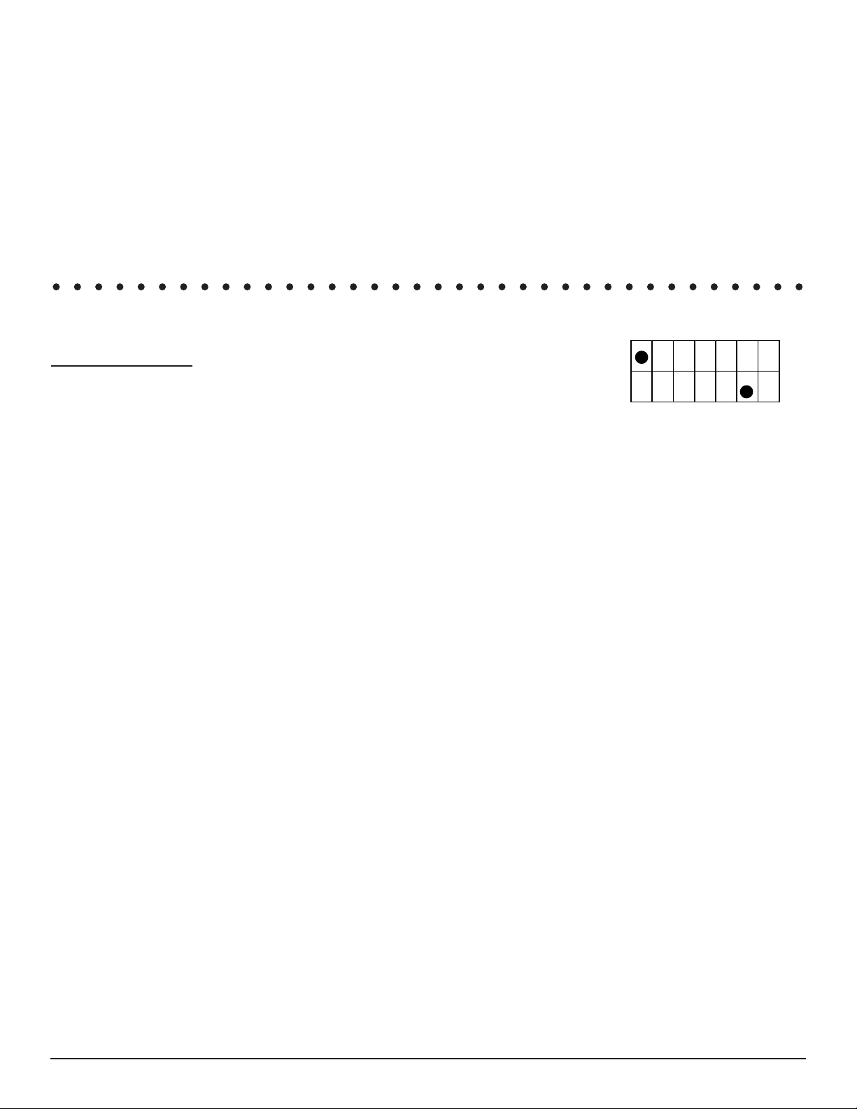
Back of remote date code sample
Warranty Information
Purchase Date: _____________ Model: _______________ Date Code: _________
Purchased From: ________________________________________________
19
20
1 2 3 4 5 6
7 8 9 10 11 12
1-12 indicates Month remote was produced.
19-20 indicates Year remote was produced.
Sample date codes above is 1911
Customer Name: ________________________________________________ Phone: _________________
Address: ______________________________________________________
City: _________________________________ State/Prov. ___________________ Zip/Postal Code _____________
E-mail Address: _____________________________________
Please send a Proof of Purchase (original receipt) copy along with your warranty form.
Skytech: 5320P
REV. 8-11-20 Page 11
 Loading...