

Operation Manual
Models: TEC6200 (Ref: 171.100) 2 x 100W RMS
TEC6300
(Ref: 171.102) 2 x 150W RMS
TEC6500
(Ref: 171.104) 2 x 250W RMS
TEC6950
(Ref: 171.106) 2 x 500W RMS
Stereo Power Amplifier
A range of high output, high quality stereo power amplifiers offering
greater reliability for a wide range of Disco, Stage and P.A. applications.
Featuring . . .
• High quality design
• Robust construction
• Low noise and low distortion
• Gain controls for each channel
• Clip indication for each channel
• Short circuit protection with
protect LED indicator
• Low noise fan cooling
• 19” Rack mounting.
0 10 0 10
LEFT RIGHT
CLIP CLIPPROTECTPOWER

2
IMPORTANT
Then wires in the mains lead are coloured in accordance with the
following code:
Green & Yellow: Earth (E)
Blue: Neutral (N)
Brown: Live (L)
As the colours of the wires in the mains lead of this apparatus may not
correspond with the coloured markings identifying the terminals in your plug
proceed as follows:
The wire which is coloured green and yellow must be connected to the
terminal which is marked by the letter E or by the safety earth symbol or
coloured green and yellow.The wire which is coloured blue must be
connected to the terminal which is marked with the letter N or coloured
black. The wire which is coloured brown must be connected to the terminal
which is marked with the letter L or coloured Red. If a 13Amp (BS1363) plug
or any other type of plug is used, a 5 Amp fuse must be fitted either in the
plug or at the distribution board.
WARNING: THIS APPLIANCE MUST BE EARTHED
OPERATION MANUAL - STEREO POWER AMPLIFIERS
WARNING: SHOCK HAZARD - DO NOT OPEN
AVIS: RISQUE DE CHOC ELECTRIQUE - NE PAS OUVRIR
CAUTION
RISK OF ELECTRIC SHOCK
DO NOT OPEN
GB
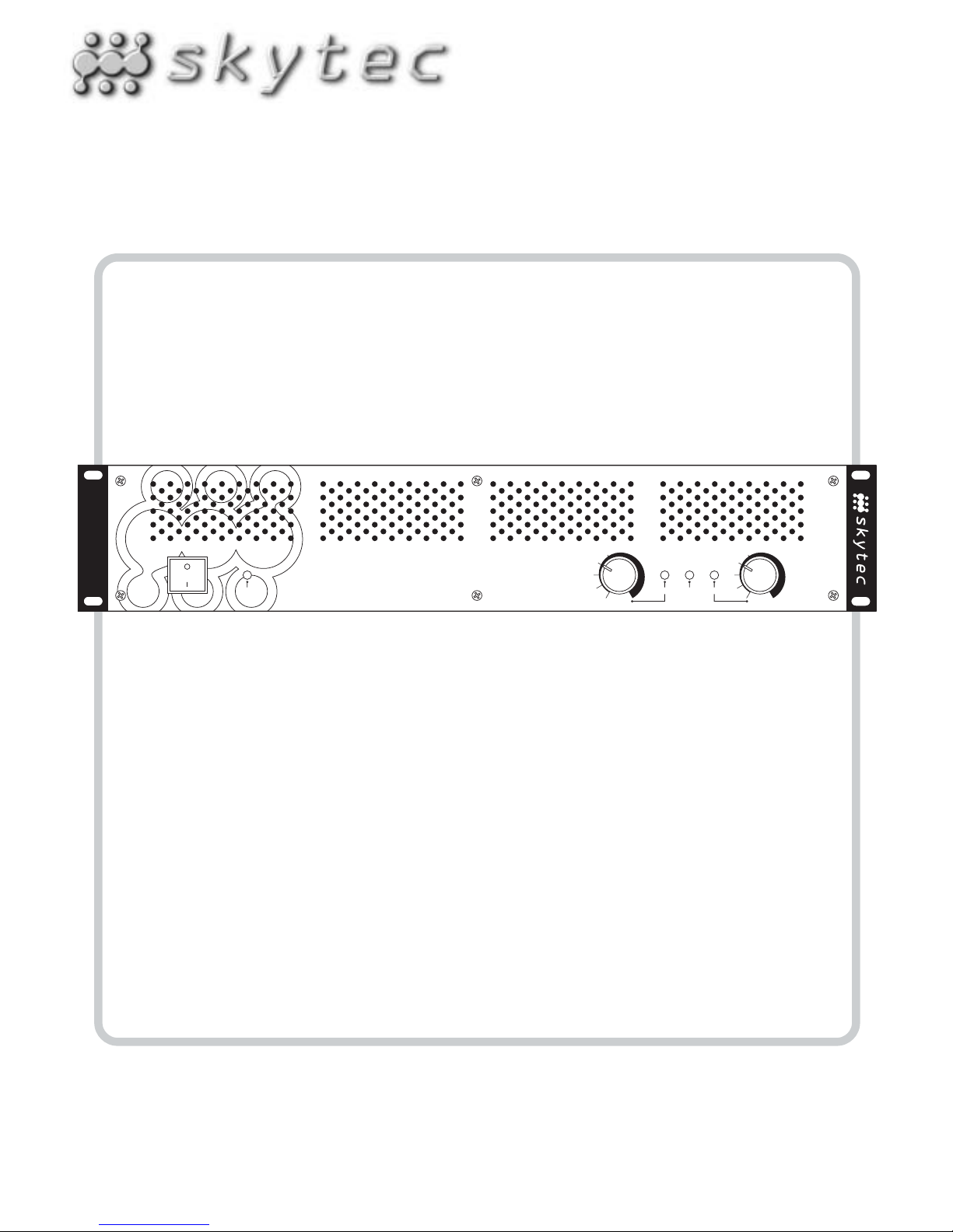
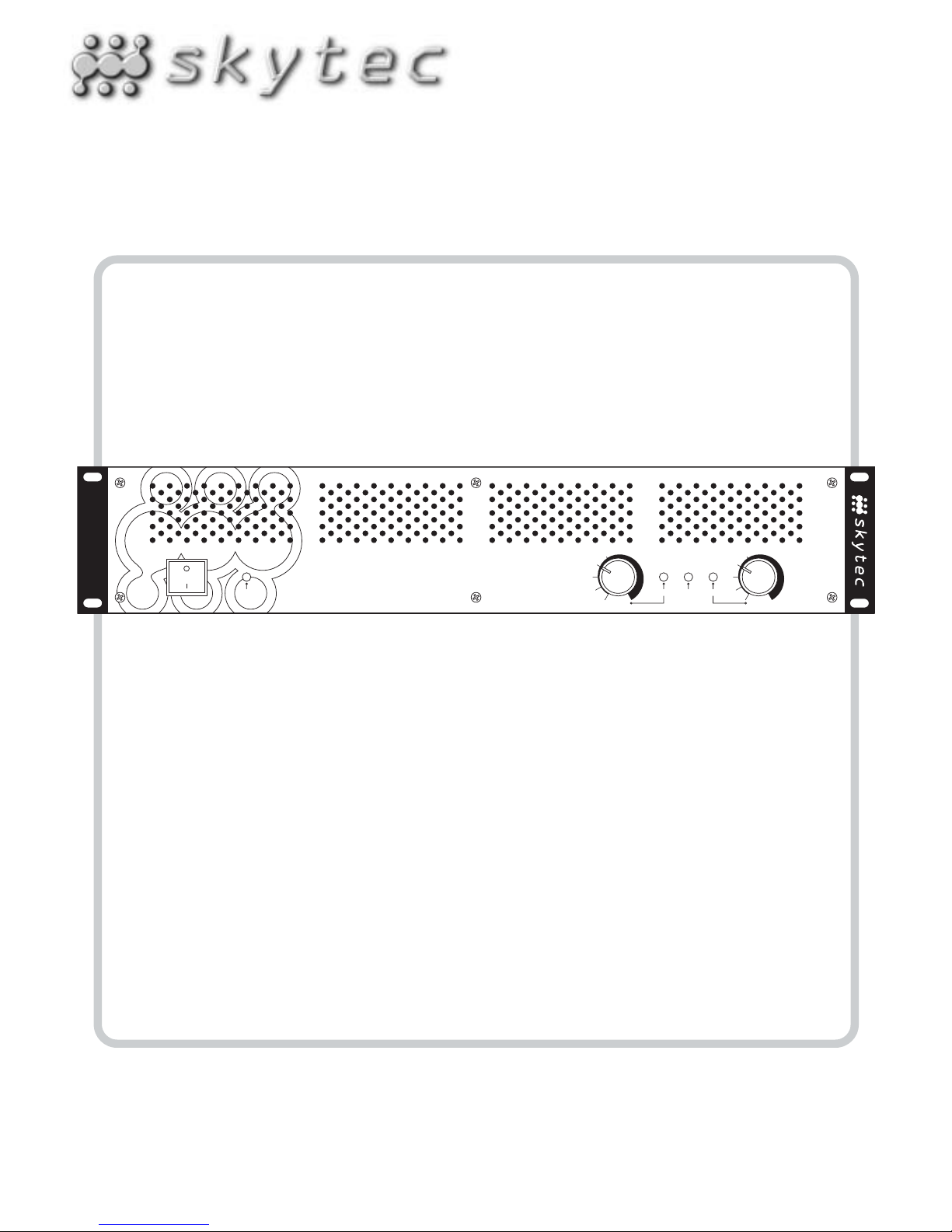
Front Panel (All models)
0 10 0 10
LEFT RIGHT
CLIP CLIPPROTECTPOWER
L
R
INPUT
OUTPUT
LEFTRIGHT
LEFT
RIGHT
Rear Panel (TEC6200 and TEC6300)
1. Power switch
2. Power on/off LED indicator
3. LH channel gain control
4. LH clip indicator
5. Protect indicator
6. RH clip indicator
7. RH channel gain control.
1. RH channel input ( 6.3mm mono socket)
2. R + L inputs ( RCA phono sockets)
3. LH channel input ( 6.3mm mono socket)
4. RH channel output ( 6.3mm mono socket)
5. LH channel output ( 6.3mm mono socket)
6. Fuse holder
7. Mains input power socket
INPUT
LEFTRIGHT
L
R
OUTPUT
LEFTRIGHT
Rear Panel (TEC6500)
1. RH channel input (Combination XLR
/6.3mm socket, unbalanced)
2. L+R channel inputs (RCA phono sockets)
3. LH channel input (Combination XLR /
6.3mm socket, unbalanced)
4. RH channel output (Speakon connector)
5. LH channel output (Speakon connector)
6. Fuse holder
7. Mains input power socket
12 34 5 6 7
12 3 4 5 6 7
12 3 4 5 6 7
Rear Panel (TEC6950)
1. RH channel input (Combination XLR
/6.3mm socket, unbalanced)
2. L+R channel inputs (RCA phono sockets)
3. LH channel input (Combination XLR /
6.3mm socket, unbalanced)
4. RH channel output (Speakon connector)
5. LH channel output (Speakon connector)
6. Mains input socket and fuse.
1 2 3 4 5 6
OPERATION
1. Connect loudspeaker system (MINIMUM load 4 ohms) with sufficient handling capacity to the output terminals of the amplifier.
2. Connect output from mixer ( or any other suitable signal source) to the appropriate input sockets of the power amplifier.
NOTE. All inputs are UNBALANCED and connections for the XLR input are Pin 1 = Gnd, 2=+IN, 3= Gnd.
3. Connect the power cord to the mains.
4. Turn gain controls to minimum , switch on the amplifier and the red power LED will illuminate.
5. Adjust gain controls to required level. NOTE. If the audio input signal is too high, distortion will result and the CLIP indicator will light.
If the clip LED is lit permanently or flashes, the gain level should be reduced.
6. Protect LED. These power amplifiers feature a unique short circuit relay protection system. When the output is shorted the amplifier
will go into protect mode with the yellow LED illuminating. Switch OFF the unit and remove the short circuit. Switch ON the amplifier
and the output will be returned immediately.
For reliable and trouble free operation, please observe the following points:
• Ensure all input / output connections are correct and secure.
• The handling capacity of the loudspeakers is adequate for the output of the amplifier.
• Always site the amplifier in a well ventilated location
• Protect unit from severe shocks
3
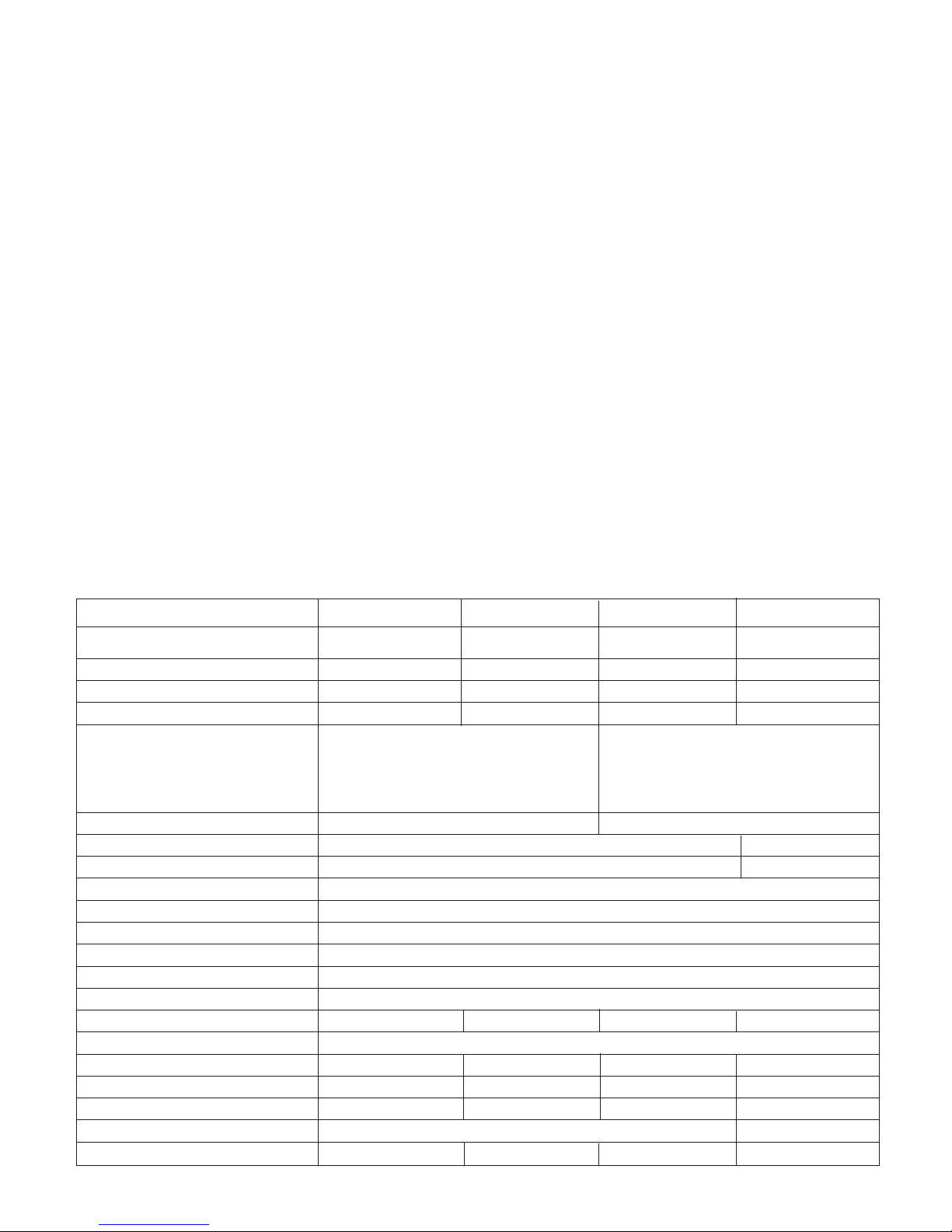
TEC6200 TEC6300 TEC6500 TEC6950
Stereo output power RMS @ 0.1% THD 2 x 100W 2 x 150W 2 x 250W 2 x 500W
Maximum output power 2 x 200W 2 x 300W 2 x 500W 2 x 950W
Single channel driven 4Ω load 110W 165W 270W 540W
Load impedance minimum 4Ω 4Ω 4Ω 4Ω
Input connectors RCA phono socket RCA phono socket
1/4” (6.3mm) jack socket Combination XLR/jack
(mono) (1=Gnd, 2=+IN, 3=Gnd)
(mono)
Output connectors 1/4” (6.3mm) jack socket (mono) Speakon (+1 /-1)
Input sensitivity 775mV 4dBBu (1.2V)
Input impedance 10K 10k
Frequency response 20Hz-20kHz ±3dB
THD +N <0.05% @ 1kHz and rated power single channel
Signal to noise ratio > 90dB
Cross-talk > 50dB @ 1kHz
Protection Protection against short circuit and DC on output
Indicators Power on, CLIP-L, CLIP-R, PROTECT
Cooling 80mm fan 80mm fan 80mm fan 80mm fan
Mains power 230V, 50Hz
Power consumption 550VA 750VA 1100VA 2100VA
Fuses AC mains T3.15A T3.15A T5A T10A
DC T3.15A T3.15A T5A T12.5A
Dimensions (WxDxH) 482 x 88 x 330mm (2U) 482 x 88 x 335mm
Weight 10kg 10.3kg 10.5kg 14kg
4
Gebruiksaanwijzing
Modellen: TEC6200 (Ref: 171.100) 2 x 100W RMS
TEC6300
(Ref: 171.102) 2 x 150W RMS
TEC6500
(Ref: 171.104) 2 x 250W RMS
TEC6950
(Ref: 171.106) 2 x 500W RMS
Stereo Power Amplifier
Een serie versterkers met een hoog uitgangsvermogen en uitmuntende
geluidskwaliteit voor gebruik in Disco, Stage en P.A. applicaties.
uitgerust met . . .
• High quality ontwerp
• Robuste constructie
• Lage S/N waarde en vervorming
• Gain controle voor ieder kanaal
• Clip indicatie voor ieder kanaal
• Kortsluitbeveiliging met
indicatieled
• Low noise ventilator koeling
• 19” Rack montage
0 10 0 10
LEFT RIGHT
CLIP CLIPPROTECTPOWER

5
Waarschuwing: Apparatuur moet worden geaard
OPERATION MANUAL - STEREO POWER AMPLIFIERS
WARNING: SHOCK HAZARD - DO NOT OPEN
AVIS: RISQUE DE CHOC ELECTRIQUE - NE PAS OUVRIR
CAUTION
RISK OF ELECTRIC SHOCK
DO NOT OPEN
NL
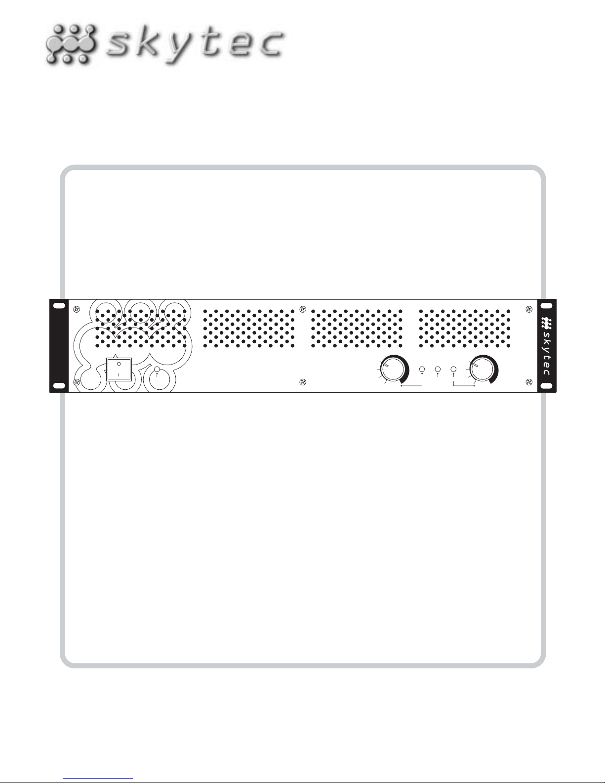
1. Netschakelaar
2. Power on/off LED indicatie
3. Linkerkanaal gain regelaar
4. Clip indicatie links
5. Protect indicatie
6. Clip indicatie rechts
7. Rechterkanaal gain regelaar.
1. Ingang rechterkanaal ( 6.3mm mono jack)
2. Rechts en Links ingang ( RCA connectoren)
3. Ingang linkerkanaal ( 6.3mm mono jack)
4. Uitgang rechterkanaal ( 6.3mm mono jack)
5. Uitgang linkerkanaal ( 6.3mm mono jack)
6. Zekeringhouder
7. IEC socket
1. Ingang rechterkanaal (Combinatie XLR
/6.3mm conn., ongebalanceerd)
2. Rechts en Links ingang (RCA connectoren)
3. Ingang linkerkanaal (Combinatie XLR
/6.3mm conn., ongebalanceerd)
4. Uitgang rechterkanaal (Speakon connector)
5. Uitgang linkerkanaal (Speakon connector)
6. Zekeringhouder
7. IEC socket
Voorzijde (Alle modellen)
0 10 0 10
LEFT RIGHT
CLIP CLIPPROTECTPOWER
L
R
INPUT
OUTPUT
LEFTRIGHT
LEFT
RIGHT
Achterzijde (TEC6200 et TEC6300)
INPUT
LEFTRIGHT
L
R
OUTPUT
LEFTRIGHT
Achterzijde (TEC6500)
12 34 5 6 7
12 3 4 5 6 7
12 3 4 5 6 7
Achterzijde (TEC6950)
1 2 3 4 5 6
1. Ingang rechterkanaal (Combinatie XLR
/6.3mm conn., ongebalanceerd)
2. Rechts en Links ingang (RCA connectoren)
3. Ingang linkerkanaal (Combinatie XLR
/6.3mm conn., ongebalanceerd)
4. Uitgang rechterkanaal (Speakon connector)
5. Uitgang linkerkanaal (Speakon connector)
6. IEC socket en zekeringhouder

6
Gebruik
1. Sluit de luidsprekers aan (MINIMAAL 4 ohms impedantie) welke het aangeboden vermogen kunnen verwerken aan op de uitgangen van
de versterkerversterker.
2. Sluit de uitgang van de mixer (of een andere geschikte signaalbron) aan op de juiste ingang van de versterker.
NOOT. Alle ingangen zijn ongebalanceerd en de specificaties voor de XLR-ingang zijn: Pin 1 = Aarde, Pin 2 = +IN, Pin 3 = Aarde.
3. Sluit de netspanning aan.
4. Draai de gain regelaar naar de minimale stand en schakel de versterker in, de rode LED zal nu oplichten.
5. Stel de gain regelaars in op het gewenste niveau. NOOT. Indien het uitgangssignaal te hoog is zal er vervorming optreden. De Clip
indicatie licht op, indien deze continue oplicht of knippert dient u de gain instelling naar beneden toe aan te passen.
6. Protect LED. Deze versterkers zijn uitgerust met een kortsluitbeveiliging. Indien een uitgang wor dt kortgesloten gaat de ve rsterker in de
Protect modus en de gele LED licht op. Schakel de versterker uit en hestel de verbindingen. Schakel de versterker in en er wordt week een
signaal aangeboden op de uitgang.
Voor betrouwbaar en probleemloos bebruik neemt u a.u.b. de volgende punten in acht:
• Verzeker u ervan dat alle aansluitingen op de juiste wijze zijn gemaakt.
• De aangesloten luidsprekers geschikt zijn voor gebruik bij de betreffende versterker.
• Zorg voor voldoende ventilatie, t.b.v. warmteafvoer.
• Voorkom blootstelling aan vocht en heftige schokken
6
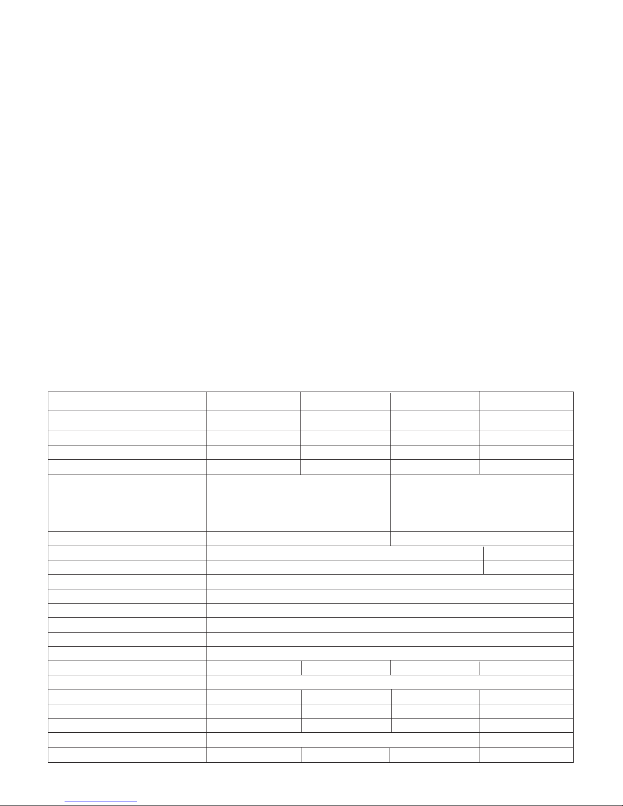
TEC6200 TEC6300 TEC6500 TEC6950
Stereo vermogen RMS @ 0.1% THD 2 x 100W 2 x 150W 2 x 250W 2 x 500W
Stereo max. uitgangsvermogen 2 x 200W 2 x 300W 2 x 500W 2 x 950W
Gebrugd vermogen (4 ohm belasting) 110W 165W 270W 540W
Impedantie minimaal 4Ω 4Ω 4Ω 4Ω
Ingangs connectoren RCA connectoren RCA connectoren
1/4” (6.3mm) jack Combinatie XLR/jack
(mono)
(1=Aarde, 2=+IN, 3=Aarde)
(mono)
Uitgangs connectoren 1/4” (6.3mm) jack (mono) Speakon (+1 /-1)
Ingangs gevoeligheid 775mV 4dBBu (1.2V)
Ingangs impedantie 10K 10k
Frequentiebereik 20Hz-20kHz ±3dB
THD +N <0.05% @ 1kHz and rated power single channel
S/N ratio > 90dB
Cross-talk > 50dB @ 1kHz
Beveiliging Beveiliging tegen kortsluiten en DC op de uitgang
Indicaties Power on, CLIP-L, CLIP-R, PROTECTIE
Koeling 80mm ventilator 80mm ventilator 80mm ventilator 80mm ventilator
Netspanning 230V, 50Hz
Opgenomen vermogen 550VA 750VA 1100VA 2100VA
Zekeringen AC T3.15A T3.15A T5A T10A
DC T3.15A T3.15A T5A T12.5A
Afmetingen (BxDxH) 482 x 88 x 330mm (2U) 482 x 88 x 335mm
Gewicht 10kg 10.3kg 10.5kg 14kg

7
Mode d’Emploi
Modèles: TEC6200 (Réf: 171.100) 2 x 100W RMS
TEC6300
(Réf: 171.102) 2 x 150W RMS
TEC6500
(Réf: 171.104) 2 x 250W RMS
TEC6950
(Réf: 171.106) 2 x 500W RMS
Amplificateur de Puissance
Stéréo
Une gamme d’amplificateurs de puissance stéréo de haute qualité qui se
caractérisent par leur fiabilité, pour une grande variété d’applications
Disco, de Scène et de Public Address
• Conception de grande qualité
• Construction robuste
• Faible bruit et faible distorsion
• Contrôles de gain sur chaque canal
• Indication de clipping sur chaque canal
• Protection contre les courts-circuits
avec indicateur lumineux
• Ventilation silencieuse
• Montage en rack 19”.
0 10 0 10
LEFT RIGHT
CLIP CLIPPROTECTPOWER

8
ATTENTION: CET APPAREIL DOIT ETRE BRANCHE
SUR UNE PRISE DE TERRE
MODE D’EMPLOI - AMPLIFICATEURS STEREO DE PUISSANCE
WARNING: SHOCK HAZARD - DO NOT OPEN
AVIS: RISQUE DE CHOC ELECTRIQUE - NE PAS OUVRIR
CAUTION
RISK OF ELECTRIC SHOCK
DO NOT OPEN
F
1. Interrupteur M/A
2. Voyant de tension
3. Contrôle de gain canal gauche
4. Indicateur de clipping canal gauche
5. Voyant de protection
6. Indicateur de clipping canal droit
7. Contrôle de gain canal droit
1. Entrée canal droit ( J.mono fem. 6.3mm)
2. Entrées G + D ( Fiches RCA femelles)
3. Entrée canal gauche (J.mono fem. 6.3mm)
4. Sortie canal droit (J.mono fem. 6.3mm)
5. Sortie canal gauche (J.mono fem. 6.3mm)
6. Porte-fusible
7. Fiche d'entrée secteur
1. Entrée canal droit (combiné XLR/J. fem.
6,3mm, asymétrique)
2. Entrées canaux G+D (RCA femelles)
3. Entrée canal gauche (combiné XLR/J. fem.
6,3mm, asymétrique)
4. Sortie canal D (Fiche Speakon)
5. Sortie canal G (Fiche Speakon)
6. Fiche d'entrée secteur et porte-fusible
Façade (tous les modèles)
0 10 0 10
LEFT RIGHT
CLIP CLIPPROTECTPOWER
L
R
INPUT
OUTPUT
LEFTRIGHT
LEFT
RIGHT
Arrière (TEC6200 et TEC6300)
INPUT
LEFTRIGHT
L
R
OUTPUT
LEFTRIGHT
Arrière (TEC6500)
12 34 5 6 7
12 3 4 5 6 7
12 3 4 5 6 7
Arrière (TEC6950)
1 2 3 4 5 6
1. Entrée canal droit (combiné XLR/J. fem.
6,3mm, asymétrique)
2. Entrées canaux G+D (RCA femelles)
3. Entrée canal gauche (combiné XLR/J. fem.
6,3mm, asymétrique)
4. Sortie canal D (Fiche Speakon)
5. Sortie canal G (Fiche Speakon)
6. Porte-fusible
7. Fiche d'entrée secteur

9
FONCTIONNEMENT
1. Branchez un système d’enceintes (charge MINIMUM 4 Ω) d’une puissance suffisante sur les fiches de sortie de l’amplificateur.
2. Branchez la sortie de la table de mixage (ou autres sources de signaux appropriées) sur les fiches d’entrée correspondantes de
l’amplificateur. NOTE: Toutes les entrées sont ASYMETRIQUES. Les connexions pour l’entrée XLR sont: Pin 1 - Masse, 2 - Entrée +, 3 Masse
3. Branchez le cordon d‘alimentation sur une prise secteur.
4. Baissez complètement les contrôles de gain et mettez l’amplificateur sous tension. Le voyant de tension rouge doit s’allumer.
5. Réglez les contrôles de gain sur le niveau requis. NOTE: Si le signal d’entrée audio est trop fort, une distor sion se produira et l’indicateur
CLIP s’allumera
6. LED de protection: Ces amplificateurs de puissance contiennent un système de protection unique par relais contre les courts-circuits.
Lorsque la sortie est en court-circuit, l’amplificateur commutera en mode de protection et la LED jaune s’allume. Eteignez
l’amplificateur et rémédiez au court-circuit. Remettez l’amplificateur sous tension.
Pour un fonctionnement stable et sans problèmes, respectez les consignes suivantes:
• Vérifiez toutes les connexions d’entrée et de sortie.
• La puissance des haut-parleurs doit convenir à la puissance de sortie de l’amplificateur.
• Placez toujours l’amplificateur en un endroit bien ventilé.
• Protégez l’amplificateur contre les chocs.
TEC6200 TEC6300 TEC6500 TEC6950
Puiss. de sortie stéréo RMS à 0.1% THD 2 x 100W 2 x 150W 2 x 250W 2 x 500W
Puissance de sortie max. 2 x 200W 2 x 300W 2 x 500W 2 x 950W
Monocanal sous 4 Ω 110W 165W 270W 540W
Impédance de charge minimum 4Ω 4Ω 4Ω 4Ω
Connecteurs d’entrée Fiches RCA femelle RCA femelle
Jack femelle 6.3mm Combiné XLR/jack
(mono) (1=Masse, 2=+IN, 3=M)
(mono)
Fiches de sortie 1/4” (6.3mm) jack socket (mono) Speakon (+1 /-1)
Sensibilité d’entrée 775mV 4dBBu (1.2V)
Impédance d’entrée 10K 10k
Bande passante 20Hz-20kHz ±3dB
THD +N <0.05% à 1kHz et puissance nom. monocanal
Rapport signal/bruit > 90dB
Cross-talk > 50dB @ 1kHz
Protection Contre les courts-circuits et DC sur la sortie
Indicateurs Tension, CLIP-G, CLIP-D, PROTECT
Refroidissement Ventilateur 80mm Ventilateur 80mm Ventilateur 80mm Ventilateur 80mm
Alimentation secteur 230V, 50Hz
Consommation 550VA 750VA 1100VA 2100VA
Fusibles secteur T3.15A T3.15A T5A T10A
DC T3.15A T3.15A T5A T12.5A
Dimensions (LxPxH) 482 x 88 x 330mm (2U) 482 x 88 x 335mm
Poids 10kg 10.3kg 10.5kg 14kg

10
Bedienungsanleitung
Modelle: TEC6200 (Best.Nr.: 171.100) 2 x 100W RMS
TEC6300
(Best.Nr: 171.102) 2 x 150W RMS
TEC6500
(Best.Nr: 171.104) 2 x 250W RMS
TEC6950
(Best.Nr: 171.106) 2 x 500W RMS
Stereo Leistungsverstärker
Diese Reihe hochwertiger Stereo-Leistungsverstärker von größter
Zuverlässigkeit eignet sich für eine große Anzahl von
Disco-, Bühnen- und PA-Anwendungen.
Sie besitzen...
• Hochwertiges Design
• Robuste Konstruktion
• Geräusch- und verzerrungsarm
• Gain-Regler auf jedem Kanal
• Clip Anzeige für jeden Kanal
• Kurzschlussschutz mit LED
Anzeige
• Geräuscharme Luftkühlung
• 19” Gerätereackeinbau.
0 10 0 10
LEFT RIGHT
CLIP CLIPPROTECTPOWER

11
WARNUNG: DIESES GERÄT MUSS AN EINE
GEERDETE SCHUTZKONTAKTDOSE
ANGESCHLOSSEN WERDEN
BEDIENUNGSANLEITUNG - STEREO LEISTUNGSVERSTÄRKER
WARNING: SHOCK HAZARD - DO NOT OPEN
AVIS: RISQUE DE CHOC ELECTRIQUE - NE PAS OUVRIR
CAUTION
RISK OF ELECTRIC SHOCK
DO NOT OPEN
D
1. Ein-/Ausschalter
2. Betriebsanzeige
3. Gainregler linker Kanal
4. Clip Anzeige linker Kanal
5. Schutzanzeige
6. Clip Anzeige rechter Kanal
7. Gain Regler rechter Kanal
1. Eingang rechter Kanal ( 6.3mm Monobuchse)
2. R + L Eingänge ( Cinch Buchsen)
3. Eingang linker Kanal ( 6.3mm Monobuchse)
4. Ausgang rechter Kanal (6.3mm Monobuchse)
5. Ausgang linker Kanal ( 6.3mm Monobuchse)
6. Sicherungshalter
7. Netzeingangsbuchse
1. Eingang rechter Kanal (XLR /6.3mm
Kombibuchse, asymmetrisch)
2. L+R Eingangskanäle (Cinch Buchsen)
3. Eingang linker Kanal (XLR /6.3mm
Kombibuchse, asymmetrisch)
4. Kanalausgang rechts (Speakon Verbinder)
5. Kanalausgang links (Speakon Verbinder)
6. Sicherungshalter
7. Netzeingangsbuchse
Frontseite (Alle Modelle)
0 10 0 10
LEFT RIGHT
CLIP CLIPPROTECTPOWER
L
R
INPUT
OUTPUT
LEFTRIGHT
LEFT
RIGHT
Rückseite (TEC6200 und TEC6300)
INPUT
LEFTRIGHT
L
R
OUTPUT
LEFTRIGHT
Rückseite (TEC6500)
12 34 5 6 7
12 3 4 5 6 7
12 3 4 5 6 7
Rückseite (TEC6950)
1 2 3 4 5 6
1. Eingang rechter Kanal (XLR /6.3mm
Kombibuchse, asymmetrisch)
2. L+R Eingangskanäle (Cinch Buchsen)
3. Eingang linker Kanal (XLR /6.3mm
Kombibuchse, asymmetrisch)
4. Kanalausgang rechts (Speakon Verbinder)
5. Kanalausgang links (Speakon Verbinder)
6. Netzeingangsbuchse und Sicherungshalter
12
BETRIEB
1. Eine Lautsprecheranlage (MINDESTLAST 4Ω) mit genügender Leistung an die Ausgangsbuchsen des Verstärkers anschließen.
2. Ausgang vom Mischpult (oder jeder anderen geeigneten Signalquelle) an die entsprechenden Buchsen am Verstärker anschließen.
HINWEIS: Alle Eingänge sind ASYMMETRISCH. Die Anschlüsse für den XLREingang sind: Pin 1 = Masse, 2= +IN, 3= Masse
3. Stecker in eine Netzsteckdose stecken.
4. Alle Gainregler ganz herunterfahren und den Verstärker einschalten. Die rote Betriebs-LED leuchtet.
5. Die Gainregler auf den richtigen Pegel einstellen. HINWEIS: Bei zu starkem Audiosignal entsteht Verzerrung und der CLIP Anzeiger
leuchtet. Wenn die CLIP LED ständig leuchtet oder blinkt, muß der Gain Pegel heruntergestellt werden.
6. Schutz LED. Diese Leistungsverstärker besitzen ein einzigartiges Schutzsystem gegen Kurzschlüsse. Wenn ein Kurzschluß am Ausgang
vorliegt, schaltet der Verstärker in Schutzbetrieb und die gelbe LED leuchtet. Schalten Sie das Gerät aus und entfernen Sie den
Kurzschluß. Gerät wieder einschalten. Der Betrieb kann nun normal weitergehen.
Für einen zuverlässigen, problemlosen Einsatz beachtenSie bitte folgende Regeln:
• Alle Ein- und Ausgangsverbindungen müssen fest und sicher sitzen
• Die Leistung der Lautsprecher muss der Ausgangsleistung des Verstärkers entsprechen
• Den Verstärker stets an einem gut belüfteten Ort aufstellen
• Das Gerät vor schwerenStössen schützen.
TEC6200 TEC6300 TEC6500 TEC6950
Stereoausg.leistung RMS @ 0.1% THD 2 x 100W 2 x 150W 2 x 250W 2 x 500W
Max. Ausgangsleistung 2 x 200W 2 x 300W 2 x 500W 2 x 950W
Einzelkanal unter 4Ω Last 110W 165W 270W 540W
Lastimpedanz mindestlast 4Ω 4Ω 4Ω 4Ω
Eingangsverbinder Cinch Buchse Cinch Buchse
6.3mm Kinkenbuchse XLR/Klinke Kombibuchse
(Mono) (1=Masse, 2=+IN, 3=M.)
(Mono)
Ausgangsverbinder 6.3mm Kinkenbuchse (Mono) Speakon (+1 /-1)
Eingangsempfindlichkeit 775mV 4dBBu (1.2V)
Eingangsimpedanz 10K 10k
Frequenzgang 20Hz-20kHz ±3dB
THD +N <0.05% bei 1kHz Einzelkanalleistung
Störabstand > 90dB
Cross-talk > 50dB @ 1kHz
Schutzvorrichtung Kurzschluß und DC am Ausgang
Anzeigen Ein, CLIP-L, CLIP-R, SCHUTZ
Kühlung 80mm Ventilator 80mm Ventilator 80mm Ventilator 80mm Ventilator
Betriebsspannung 230V, 50Hz
Stromverbrauch 550VA 750VA 1100VA 2100VA
Sicherungen Netz T3.15A T3.15A T5A T10A
DC T3.15A T3.15A T5A T12.5A
Abmessungen (BxTxH) 482 x 88 x 330mm (2U) 482 x 88 x 335mm
Gewicht 10kg 10.3kg 10.5kg 14kg
13
Bruger vejledning
Typer: TEC6200 (Varenr:171.100) 2 x 100W RMS
TEC6300
(Varenr:171.102) 2 x 150W RMS
TEC6500
(Varenr:171.104) 2 x 250W RMS
TEC6950
(Varenr:171.106) 2 x 500W RMS
Stereo Effektforstærker
Serie af effektforstærkere til professionel anvendelse.Velegnet til discotek,
musiker, orkester, scene, teater etc.
Features .. .
• High quality design
• Robust konstruktion
• Lav støj og lav forvrængning
• Gain regulering for hver kanal
• Clip indikation for hver kanal
• Beskyttelses kredsløb mod
kortslutning og LED indikator
• Low noise blæserkøling
• 19” Rack montering
0 10 0 10
LEFT RIGHT
CLIP CLIPPROTECTPOWER

14
VIGTIGT
Inderlederne i lysnetkablet er farvekodet efter følgende
standard kode:
Grøn & Gul: Jord (E)
Blå: Nul (N)
Brun: Fase (L)
Inderlederne skal forbindes til de tilsvarende terminaler i den anvendte
stikprop.
Lederen med farvekoden grøn og gul,skal forbindes til terminalen i
stikproppen mærket E eller med symbolet for jordforbindelse. Lederen
med farvekoden blå skal forbindes til terminalen i stikproppen mærket
N eller nul (neutral). Den sidste leder,med farvekoden brun,skal
forbindes til den terminal der er mærket L eller fase (Live).Apparatet
må udelukkende tilsluttes en lovlig 230Vac elinstallation, med 10A
sikring ved installationens hovedmåler/eltavle.
BEMÆRK: DETTE APPARAT SKAL JORDFORBINDES
BRUGER MANUAL - STEREO EFFEKTFORSTÆRKERE
ADVARSEL: DET ER FORBUNDET MED
LIVSFARE AT ÅBNE APPARA TET
ADVARSEL
RISIKO FOR ELEKTRISK SHOCK
MÅ IKKE ÅBNES
DK
1. Tænd/sluk kontakt
2. Tænd/sluk LED indikator
3. Venstre kanal, gain kontrol
4. Venstre kanal, clip indikator
5. Protect indikator
6. Højre kanal, clip indikator
7. Højre kanal, gain kontrol.
1. Højre kanal, indgang (6.3mm mono jack)
2. H + V indgange (RCA phono bøsninger)
3. Venstre kanal, indgang (6.3mm mono jack)
4. Højre kanal, udgang (6.3mm mono jack)
5. Venstre kanal, udgang (6.3mm mono jack)
6. Sikringsholder
7. Indgangsbøsning til netspænding
1. Højre kanal, indgang (kombineret XLR
/6.3mm jack,unbalanceret)
2. H + V kanal,indgange (RC A phono)
3. Venstre kanal, indgang (kombineret XLR /
6.3mm jack,unbalanceret)
4. Højre kanal, udgang (Speakon stik)
5. Venstre kanal, udgang (Speakon stik)
6. Sikringsholder
7. Indgangsbøsning til netspænding
Forside (alle typer):
0 10 0 10
LEFT RIGHT
CLIP CLIPPROTECTPOWER
L
R
INPUT
OUTPUT
LEFTRIGHT
LEFT
RIGHT
Bagside (TEC6200 og TEC6300):
INPUT
LEFTRIGHT
L
R
OUTPUT
LEFTRIGHT
Bagside (TEC6500)
12 34 5 6 7
12 3 4 5 6 7
12 3 4 5 6 7
Bagside (TEC6950)
1 2 3 4 5 6
1. Højre kanal, indgang (kombineret XLR
/6.3mm jack,unbalanceret)
2. H + V kanal,indgange (RC A phono)
3. Venstre kanal, indgang (kombineret XLR /
6.3mm jack,unbalanceret)
4. Højre kanal, udgang (Speakon stik)
5. Venstre kanal, udgang (Speakon stik)
6. Indgangsbøsning til netspænding og
sikringsholder

15
IBRUGTAGNING / INSTALLATION
1. Tilslut højttalerne til udgangsbøsningerne . Disse skal være MINIMUM 4 ohm, og kunne tåle den nødvendige effekt.
2. Tilslut indgangssignal fra mixeren (eller tilsvarende liniesignal kilde) til de ønskede indgangsbøsninger på forstærkeren.
BEMÆRK:Alle indgange er UNBALANCEREDE og kodning for XLR indgangene er Pin 1 = Gnd,2=+IND, 3= Gnd.
3. Tilslut lysnetkablet til en 230 Vac / 50 Hz stikkontakt.
4. Drej begge Gain-kontroller til MINIMUM.Tænd forstærkeren,og den røde LED lyser.
5. Juster Gain-kontrollerne til det ønskede niveau. BEMÆRK: Hvis indgangssignalet er for kraftigt,vil forstærkeren forvrænge og CLIP
lysdioderne lyser/blinker.Skru omgående ned for gainkontrollerne således,at CLIP indikatorerne ikke lyser.
6. Protect LED. Disse effektforstærkere er konstrueret med et unikt beskyttelseskredsløb, der udkobler hvis forstærkeren er
kortsluttet på højttalerudgangen. Hvis kredsløbet registrerer en kortslutning,udkobles forstærkeren og Protect LED’en lyser gult.
Sluk straks apparatet,fjern kortslutningen, og tænd igen. Hvis kortslutningen er væk,star ter forstærkeren straks igen.
For problemfri drift,bemærk da følgende:
• Check at alle indgange/udgange er korrekt og forsvarligt tilsluttet - uden kortslutninger i stik etc. Check også polaritet (+/-).
• Vær sikker på,at de tilsluttede højttalere er på min.4 ohm, og kan tåle forstærkerens udgangseffekt.
• Forstærkeren skal placeres et sted med god ventilation, alm.stuetemperatur og fugtfrit.
• Undgå overbelastning,samt stød og slag på apparatet.
TEC6200 TEC6300 TEC6500 TEC6950
Stereo udganseffekt RMS @ 0.1% THD 2 x 100W 2 x 150W 2 x 250W 2 x 500W
Maximum udgangseffekt 2 x 200W 2 x 300W 2 x 500W 2 x 950W
Enkelt kanal i 4Ω belastning 110W 165W 270W 540W
Minimum impedans,højttaleree 4Ω 4Ω 4Ω 4Ω
Indgangs bøsninger RCA phono bøsninger RCA phono bøsninger
1/4” (6.3mm) jack bøsninger Kombineret XLR/jack
(mono) (1=Gnd,2=+IN, 3=Gnd)
(mono)
Højttaler tilslutning (udgange) 1/4” (6.3mm) jack bøsning (mono) Speakon (+1 /-1)
Indgangs følsomhed 775mV 4dBBu (1.2V)
Indgangs impedans 10 Kohm 10 Kohm
Frekvens område 20Hz-20kHz ±3dB
THD +N <0.05% @ 1kHz og max effekt,1 kanal
Signal / støj forhold > 90dB
Cross-talk > 50dB @ 1kHz
Beskyttelse Kortslutning og DC på udgangen
Indikatorer Tændt, CLIP-L,CLIP-R, PROTECT
Blæserkøling 80mm blæser 80mm blæser 80mm blæser 80mm blæser
Strømforsyning 230V,50Hz
Effektforbrug 550VA 750VA 1100VA 2100VA
Sikringer, AC lysnet T3.15A T3.15A T5A T10A
DC T3.15A T3.15A T5A T12.5A
Dimensioner (BxDxH) 482 x 88 x 330mm (2U) 482 x 88 x 335mm
Vægt 10kg 10.3kg 10.5kg 14kg

www.skytronic.com
 Loading...