

Skytec STX-120 User Manual
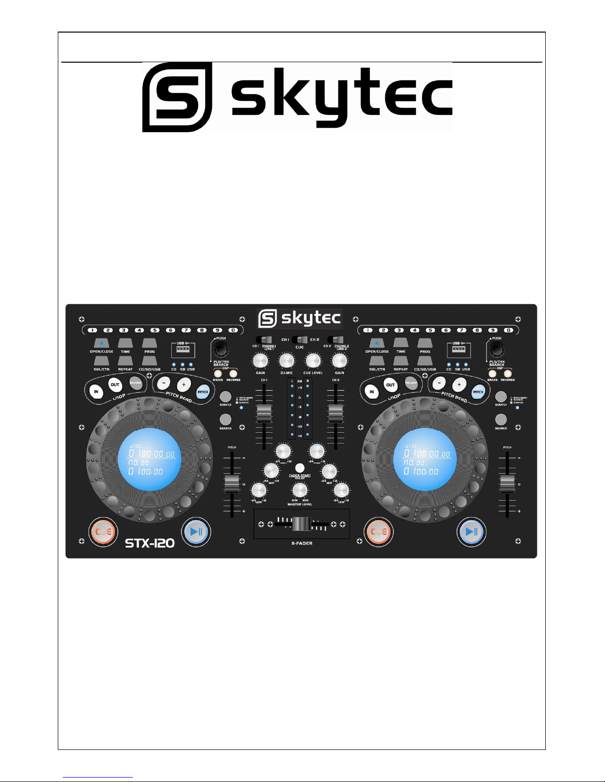
STX-120
PROFESSIONAL DUAL CD/USB/SD
MIXING CONSOLE
172.812
USER’S MANUAL
HANDLEIDING
GEBRAUCHSANLEITUNG
2
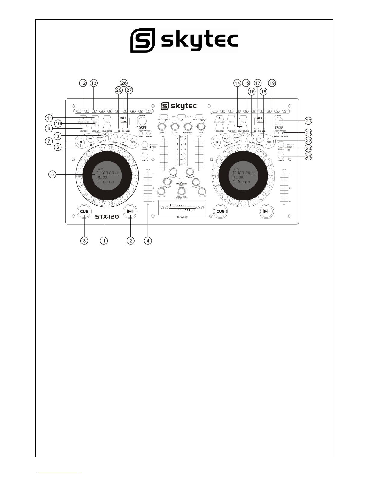
TOP VIEW
IMPORTANT
Use of controls or adjustments or performance of procedures other than those specified herein may
result in hazardous radiation exposure.
CD player Function:
1. JOG & SHUTTLE WHEELS
Shuttle: Use the dial to select the scanning direction and speed. The disc is scanned in the
forward direction when the shuttle dial is turned clockwise from the neutral position, in the reverse
direction when the shuttle dial is turned counterclockwise. The scanning speeds up when the
shuttle dial is turned faster.
Jog: In pause mode, if you turn the jog, the point at which the sound is being produced moves by
a number of frames corresponding to the number of clicks. Clockwise moves the point forward;
counterclockwise moves the point backward. In play mode, the jog increases or decreases the
speed of the song. (Clockwise: increase, counterclockwise: decrease).
2. PLAY/PAUSE BUTTON
Each time you press the PLAY/PAUSE button, the operation changes from play to pause or from
pause to play.
3. CUE BUTTON
Pressing the CUE button during play provides a return to the position at which play was started.
4. PITCH CONTROL
Use this fader to increase or decrease the speed of the track.

3
4. DISPLAY
LCD Display lndicate the Track/Numbers/Time/Remain/Pitch/Continue/Single.
5. IN BUTTON ( LOOP SYSTEM )
This button sets the beginning of the loop. The Loop indicator on the display flashes.
6. OUT BUTTON ( LOOP BUTTON )
When you press this button, you set the end point of the seamless loop and you start the loop. To
finish the loop, press again this button.
7. RELOOP BUTTON ( LOOP SYSTEM )
This button is used to start the last saved loop. To finish the loop, press the reloop button.
8. CONT. / SINGLE BUTTON
Press these to switch between the SINGLE and CONTINUOUS play mode. The selected mode is
indicated on the LCD. In SINGLE mode, after each track, the unit stops the reading. In
CONTINUOUS mode, the unit read all track and stops.
9. REPEAT BUTTON
Use this button to repeat one track or all the track of the CD.
10. TIME BUTTON
Used this knob to choose the time mode : Elapsed time, remaining time or total remaining time.
11. OPEN/CLOSE BUTTON
Press to load or eject disk. Each press will open or close the disk tray.
NOTE: disc holder will not open unless stop or pause button has been pushed fir.
12. TRACK SELECT BUTTONS
Pressing 0-9 buttons, allow you to select tracks from the CD.
13. CD/USB/SD BUTTON
Press this button to choose CD or USB or SD mode while USB connect and the CDs in the tray
and the SD CARD insert the main unit.
14. PROG BUTTON
In STOP mode, you can program several tracks (20 tracks max.):
- Press the STOP button to enter in the stop mode
- Press the PROG button to enter in the program mode
- Use the skip track buttons to choose the track you want to listen then press the PROG button to
enter your choice.
- Use one more time the skip track buttons to choose the track you want to listen then press the
PROG button to enter your choice.
- Repeat the operation to select all the track you want to listen
- Press the PLAY / PAUSE button to start the playback
15. PITCH BEND - BUTTON
The pitch will drop while the - button is pressed and return to the original pitch when it is released.
16. USB PORT
Allows the connection of any USB memory stick.
17. PITCH BEND + BUTTON
The pitch will automatically rise when the + button is pressed and return to the original pitch when
it is released.
4
18. PITCH BUTTON
If you push this button, the adjustement of the pitch potentiometer is available.
19. FOLDER/TRACK SEARCH
Allows you to navigate through folders or tracks similarly in either USB or CD mode. When
navigating a standard CD turn the rotary to the right to advance the selection or turn the rotary to
the left to decrease the selection.
20. DSP/REVERSE
Push the reverse button to play your track in reverse, push the reverse button again to cancel this
feature.
21. DSP/BRAKE
In play mode, push the brake button at first, and then push play/pause button, the operation
changes is slowness from play to pause, push play/pause button again to cancel this feature.
22. SCRATCH BUTTON
When the LED indicator is flashed the dual wheel is in SCRATCH mode, you may press the
SCRATCH button to exit SCRATCH mode.
23. SEARCH BUTTON
Pressed the button to switch the function of jog dial between SEARCH and PITCH BEND, when
the indicator LED is light, dial the jog for quick search forward and backward, when the indicator
LED is off, dial the jog for pitch bend functional the jog is unmoved for 8 seconds, the indicator is
off, and the jog is for pitch bend function.
24. WHEN YOU ENTER INTO CD WORK MODE. THE LAMP CAN LIGHT.
25. WHEN YOU ENTER INTO SD WORK MODE. THE LAMP CAN LIGHT.
26. When you enter into USB work mode. the lamp can light.
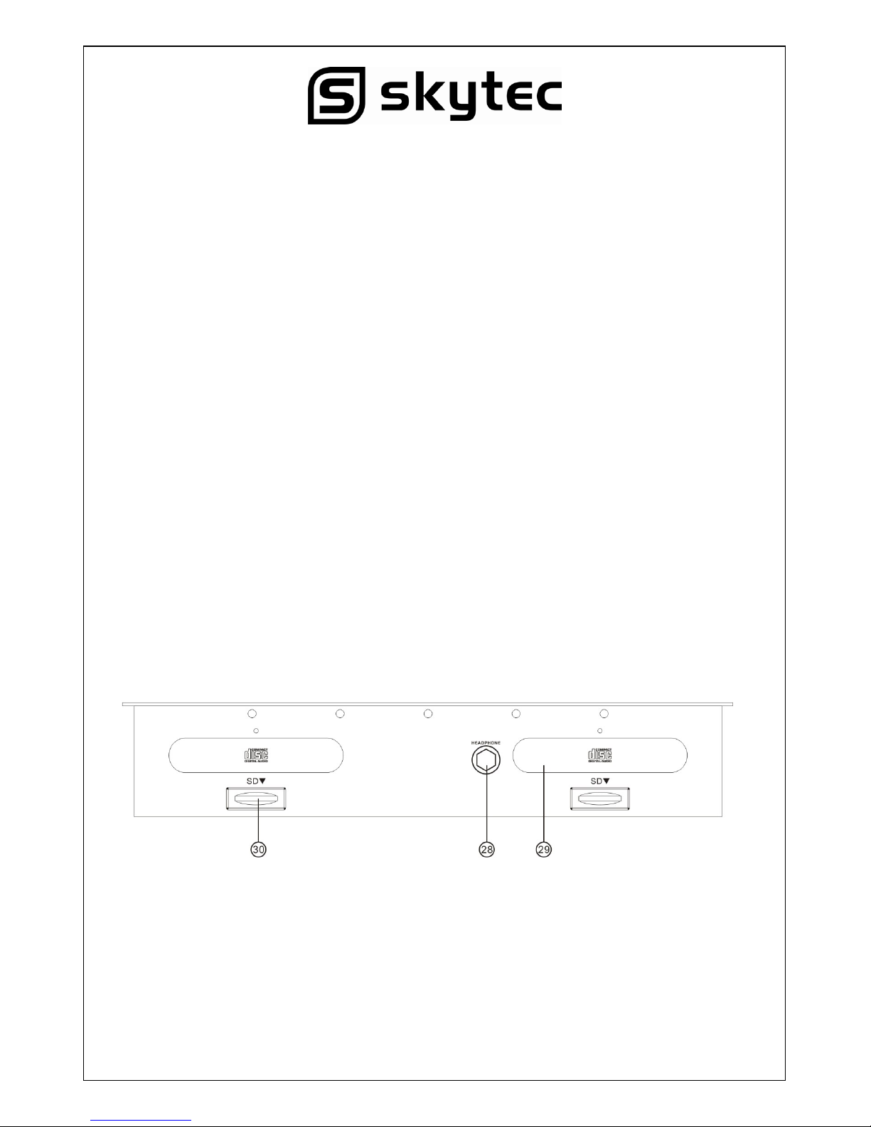
FRONT VIEW
28. HEADPHONE JACKS
Use to connect for audio monitoring with headphones.
29. DISC-TRAY
To enter the disc, please refer to the explanations under 6.2 CD-tray.
30. SD CARD PORT
Support SD playing but only when enter into SD work mode.
5
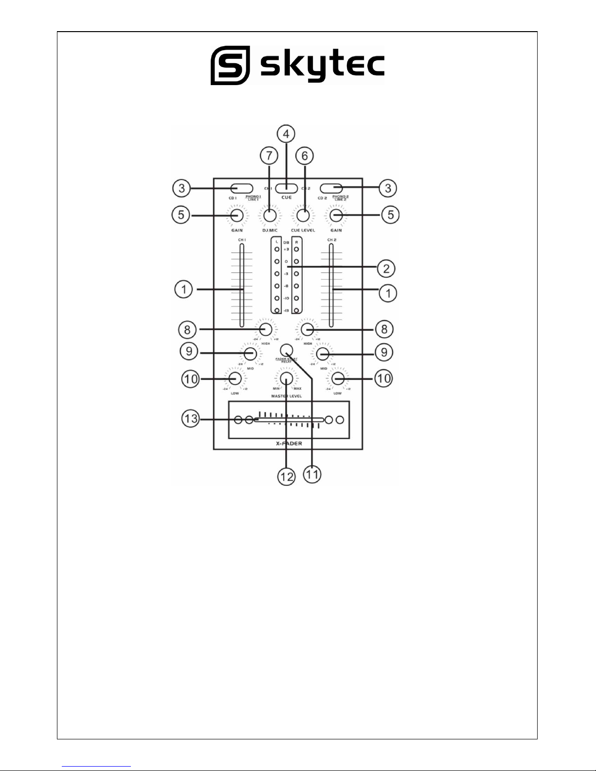
Mixing Console Function:
1. INPUT FADER
Controls individual source levels for CH1-2 in the mix.
2. LED METER
Indicates the master output level.
3. INPUT TOGGLE SWITCH
Selects which source will be live to that channel based on what you have connected to the rear
panel input section. In CD1-2 position the internal CD units are active.
4. CUE FOR CH1-2
Selects which source will be live to that channel for CH1 &CH2.
5. CH1&CH2 GAIN CONTROL
Adjusts CH1&CH2 level
6. CUE LEVEL CONTROL
Adjusts Cue volume
7. DJ. MIC
Adjusts microphone level
6
8. HIGH FADER 1-2
Adjust CH1&CH2 equalization of high frequencies.
9. MID FADER 1-2
Adjust CH1&CH2 equalization of mid frequencies.
10. LOW FADER 1-2
Adjust CH1&CH2 equalization of low frequencies.
11. FADER START
Activation allows you to start the CD players from you crossfader. Travel from left to right will start
the right CD player and pause the left CD player.
12. MASTER LEVEL
Adjusts master level output signal.
13. REPLACEABLE CROSSFADER
Achieves clean segues between the two input channels. Hard left selects channel 1.”Hard right”
selects channel 2. With the crossfader centered, both assigned channels are live. Use the
crossfader for fast and seamless segues from one selected channel to the other.
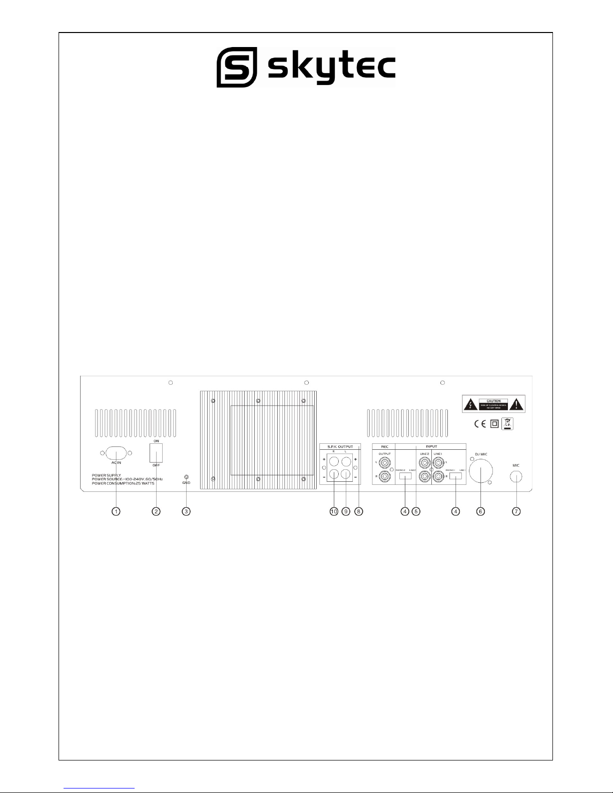
Connections:
1. AC CORD
Use this cable to connect the AC mains power to the unit.
2. POWER BUTTON
Press the power switch to turn the unit on. To switch the POWER off press the POWER switch
again.
3. GND
Grounding lug for turntable connection. Always use this connection when using turntables (your
turntable cable should have a grounding wire).
4. LINE/PHONO INPUT SWITCH
Use this to allow either line level or phono level equipment to be plugged into your channel inputs
when phono input is selected, your signal is fed directly to the high-quality RIAA phono preamplifiers. Line level sources will overload the sensitive phono pre-amps and will sound very bad,
so always be sure to toggle the line/phono switch over to line before connection of line sources.
7
5. INPUT
Plug in the line level device such as tape deck or additional CD player here.
6. DJ MIC
Plug XLR type microphone plug in here.
7. MIC INPUT
Plug 1/4” microphone plug in here.
8. STEREO MAIN OUTPUT
Unbalanced RCA connectors controlled by the master fader.
9. SPEAKER OUTPUT LEFT
Speaker left channel output terminal connecting to left channel speaker.
10. SPEAKER OUTPUT RIGHT
Speaker right channel output termial connecting to right channel speaker.
WARRANTY CONDITIONS
skytec equipment is covered by a 1-year warranty on parts and labour except for faders(90 days).The
follwing rules apply from the day the equipment leaves the factory:
The date on the invoice is considered to be the date the warranty begins.
Only companies approved by Tronios are allowed to work on the equipment.Warranty becomes void
when other service technicians open the equipment.
During warranty period,defective equipment must be sent by pre-paid mail in the original box.
Tronios will return the goods by pre-paid mail during the first year of warranty;thereafter the mailing
cost is to be paid by the recipient.
Potentiometers have a limited lifetime and are not covered by the manufacturer for more than normal
use.
For all service enquiries,refer to your local distributor,as he is best able to help you.
SPECIFICATIONS:
Anti-Shock Buffer Memory: 40 seconds
Power supply: ~220-240V,/50Hz
Dimensions : 482 x 260 x 122mm
 Loading...