

Skytec STM-3007 Instructions Manual
USER GUIDE
STM-3007
INSTRUCTIONS
GEBRUIKSAANWIJZING
BEDIENUNGSANLEITUNG

172.736
Safety Precaution
Read all documentations carefully before operating the equipment.Retain this manual for future reference.Follow all
instructions printed on unit for proper operation.
Do not open cover (or back cover) to reduce the risk of electric shock or fire.
There are no user serviceable parts inside.Refer servicing to qualified service Personnel.
This symbol is used to alert the poerator to the presence of important operationg instructions and precautions detailed in
the documentation manual.
This symbol is used to warn operators that uninsulated dangerous voltages are present within the products enclosure that
may pose a risk of electric shock.
Warning: To avoid fire or risk of electric shock,do not expose this unit to rain or moisture.
Notes:
.Make sure power outlets conform to the power requirements listed on the back of the unit.
.Main voltage must be correct and the same as that printed on the rear of the unit.
.Do not use the unit if the electrical cord is frayed or broken.
.The unit shall not be exposed to dripping or splashing and that no objects filled with liquids,such as vases, shall be placed
on unit.
.The unit shall be connected to mains socket outlet with a protective earthing connection.
.Power plug sa a equipment that separate from power supply system, it must be easy to operating.
Warning:
.Using, adjustintg or changing program control beyond this specification may cause dangerous radiation.
.The unit should be serviced by qualified service personnel.
.When repairing,use only same specification parts.
Notes:
.Select the voltage requirement through the voltage selector switch at the real panel.
.Make sure that the power of the equipment is off and disconnected from the main voltage before switching the voltage
selector to the required setting .We will not be responsible for damages arising from the improper installation,wiring or
operation due to the fault or negligence of the user.
Record your model and serial number here:
Importance:
1) Read manual ---Please read through safety and operating instruction carefully before using this unit.
2) Keep manual ---Please keep this manual for future reference.
3) Attach importance to warning and note ---Please operate it according warning and bote of manual.
4) Do it according what the manual indicates ---Do it according to instruction of manual.
5) Water and moisture---Position of the unit don’t close to awter. E.g.close to bath,wash by tub,washtub,
6) Carriage and rack ---The unit ought to match carriage and rack that manufacturer recommended.
Please be careful while carriage with the unit is moving.
Sudden stop,great power and rough surface may cause combination turns over.
7) Fix on wall or ceiling ---Manufacturer suggest product only be fixed on wall or ceiling.
8) Heat ---Device do not leave heat source such as radiator,stove and amplifier etc.
9) Power supply ---The unit only operate with rated power supply.Please ask dealer or local power supply company
while not ensure type of power supply .If operationg with batteries or other power supply, please refer to this booklet.
10) Connectiong ground or polarization ---Perhaps this unit has a polarization AC plug. This plug only has a method to be
inserted.Its characteristic is safety.

11) Power cord protect ---Power cord do not be trampled or be pressed.
12) Clean ---Clean this unit with a soft cloth. Prevent water to enter into inner.
13) For device with AC power cord,check AC plug sheet and all of exposed metal parts with ohmmeter before using ,and
resistance ought to be more than 100K ohm.
14) Stop period --- Unplug the power cord if the unit is not used for a long time.
15) Prevent solid and liquid to enter into unit --- Be CARE FULLY ,DO NOT FALL SOLID OR SPATTER LIQUID AT
HOLE OF UNIT.
16) Mangle for repair --- If cause following case ,refer to qualified service personnel:
A) Power cord or plug mangle; or
B) Inside of unit have falling solid or liquid; or
C) The unit be rained ; or
D) Device do not work; or
E) The unit be fallen,or cover be mangle.
17) Repair ---User do not repair unit except operating to depend on manual instruction. All of above symptoms should
refer to qualified service personnel.
18) Ventilation --- Function of cover’s interval and hole is ventilation. It ensure operationg reliability and prevent to
overheat. Do not cover this hole absolutely. Do not place unit on bed , blandet, sofa or similar object’s surface .Do not
place unit in object’s inner,such as bookcase’s inner, Shelf’s inner etc.
19) Accessories---Not use parts that manufactory do not recommend in order to avoid damage.
20) Auxiliary equipment ---Do not place this unit on unstable vehicle,shelf,tripod or table. It will cause serious harm to
child or adult if the unit be fallen. Pleasel use the vehicle, shelf, tripod or table that manufactory recommen.
21) Preventing thunderbolt---Add preventing thunderbolt equipment, or if the unit is not used for a long time, unplug the
power cord.
22) Replace parts---If the unit require replacing part, you must replace with manufactory recommend, or same
characteristic part.
23) Safety check---After repairing, repairer must test the unit for security.
Not On Use
Allow for sufficient heat dispersion when installed on a rack.
1) Handle the power cord carefully.
Hold the plug when unplugging the cord.
2) Keep the set free from moisture,water and dust.
3) Unplug the power cord when not using the set for long periods of time.
4) Do not obstruct the ventilation holes.(For sets with ventilation holes.)
5) Do not let foreign objects in the set.
6) Do not let insecticidese, benzene, and thinner come in contact with the set.
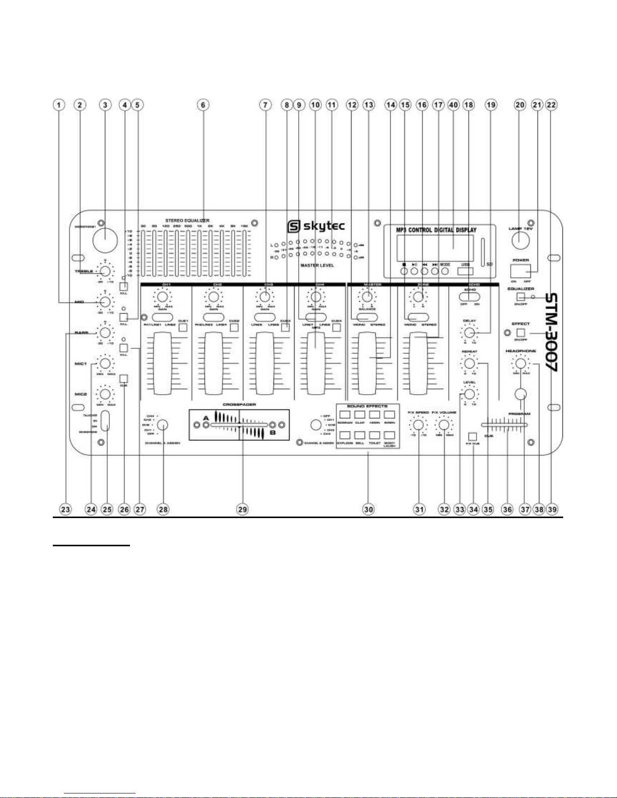
Front Panel
1)MIC MID
This knob adjusts the middle tone of the microphone.
2)MIC TREBLE
This knob adjusts the high tone of the microphone.
3)MIC INPUT JACK
Connect your MIC at this location.
4)KILL FOR TREBLE
Press it to kill microphone trreble volume, and indicator light.
5) KILL FOR MID
Press it ro kill microphone middle volume, and indicator light.
6) EQUALIZER
Allow you to tailor the mixer output to suit be cut or boost by up to 10dB.
7) CHANNEL GAIN
This rotary control adjusts theinput level.

8) CHANNEL CUE
Use it to monitor the selected audio input source.
9) CHANNEL INPUT SELECTOR
Let you to choose the input source to play for each channel.
10) CHANNEL LEVEOL CONTROL
Let you control mixer’s overallchannel volume level.
11) DISPLAY METER
Indicate the levels of left and right master channels.
12) MASTER MONO/STEREO SELECTOR
Select mono mode or stereo mode.
13) MASTER BALANCE CONTROL
Let you adjust master balance.
14) MASTER LEVEL CONTROL
Let you control mixer’s overall master volume level.
15) ZONE MONO/STEREO SELECTRO
Select mono mode or stereo mode.
16) ZONE BALANCE CONTROL
Let you adjust zone balance.
17) ZONE LEVEL CONTROL
Let you control mixer’s overall zone volume level.
18) ECHO ON/OFF
Turn echo on or off
19) ECHO DELAY CONTROL
Let you adjust the delay tine for echo.
20) 12V POWER SUPPLY JACK
Allow you to connect 12v power supply via this jack.
21) POWER SWITCH
Use this switch to turn on the unit after all input devices are already connected to prevent damage to you equipment. Turn
the mixer on before you turn on amplifier and turn of amplifiers before you turn off the mixer.
22) EQUALIZER ON/OFF
Press it to turn equalizer on, the indicator light.
23) MIC BASS
This knob adjusts the bass tone of the microphone.
24) MIC LEVEL CONTROL
Let you control the MIC level as they enter the mix.
25) MIC TALK OVER
There are talk over, MIC on and MIC off funtion. The Sound Pressure Level of audio frrom input sources will be decreased
while TALK OVER mode is set
26) MIC CUE
Use it to monitor the MIC input source
27)KILL FOR BASS
Press it tot kill microphone bass volume, and indicator light.
28) CHANNEL ASSIGN SELECTOR
Let you select the input source to be mixed by the crossfader control.
29) CROSSFADER
Allow you to smoothlu switch between the input sources assigned to channel A and channel B.
30) SOUND EFFECTS
Let you create special sound performance mixes from the eight preprogrammed special effects.
31) SOUND EFFECTS SPEED CONTROL
Let you control the pitch of the selected sound effect.
32) SOUND EFFECTS VOLUME CONTROL
Let you control the volume level of the sound effect within the mix.
33) ECHO LEVEL CONTROL
Control the depth of the echo effect.
34) SOUNCD EFFECTS CUE
Let you monitor the selected sound effect before mixing it in.
35) ECHO REPEAT CONTROL
Let you control the time period during which the echo is repeated.
36) HEADPHONE CUE/PGM CONTROL
Allow you to listen simultaneously or separately to the CUE material or the active program.
37) HEADPHONE JACK
Accept headphone with 1/4” plug.
38) HEADPHONE LEVEL CONTROL
Let you to control the volume level of headphone.
39) EFFECT SWITCH (SEND/ RECEIVE)
Let you connect a sound effect device, such as reverb, sampler, etc. and either play the signal from it or play anpther input
through it.
40)MP3 PLAYER AND BLUE TOOTH
a)USB/SD:Connect to USB stick and SD card.
b)ID3 Display:Display to MP3's information.
c) Five Buttons from left to right function as follows
c1)Stop
Use this button to stop this music.
c2)Play/pause
Each time you press this button, the operation changes from play to Pause or from pause to play.
C3)|<< PREVIOUS
Use this button to re-start the track or to select the previous track.
C4)>>| NEXT
Use this button to select the next track.
C5)mode select
Short press to select the usb/sd and blue tooth function.long press to turn on/off the mode.

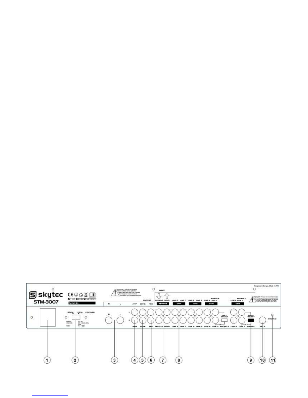
Rear Panel
1) POWER SUPPLY INPUT JACK
Input voltage from this jack.
2) VOLTAGE SELECTOR
Select voltage which you need.
3) 1/4” OUTPUT JACKS
Connect the mixer to a receiver use cables with 1/4” plugs
4) AMP OUTPUT JACKS
Connect the mixer to a amplifier use cables.
5) ZONE OUTPUT JACKS
Connect the mixer to a second receiver or amplifier powering speakers in the DJ booth or in a remote location.
6) RECORD OUTPUT JACKS
Connect the mixer to a second receiver or amplifier powering speakers in the DJ booth or in a remote location.
7) EFFECTS SEND/RECEIVE JACKS
Permit you to either include externally generated effects (such as a digital sampler) in the mix, or to process the mixed
sound (echo recerb, ect.)
8) LINE INPUTS
Let you connect most high-level audio source, such as CD players, tape deck, tuner or VCR.
9) INPUT SELECTOR
Set these swithches based on what is plugged into Phono/ Line input jacks.
10) MIC JACK
Microphones with a 1/4” connector can be connected to these input terminals.
11) GROUND
Ground Screw for turntables.
Specifications
Input Sensitivity/ Impedance
MIC 1-2--------------------------------------1.5mV/ 600 Ohms, bal/unbal
Phono 1-2------------------------------------3.0mV/ 50K Ohms
Line 1-8--------------------------------------150.0 mV/27K Ohms
Output Level
Amp-------------------------------------------2.0V/10K Ohms
Zone------------------------------------------2.0V/10K Ohms
Record---------------------------------------150Mv/10K Ohms
Frequency Response-----------------------20Hz-20kHz +/-3 dB
S/N Ratio ( at 1 kHz)
MIC ------------------------------------->60 dB/ 1.5mV input
Phono ------------------------------------>60 dB/ 3.0mV input
Line -------------------------------------->65 dB/ 150mV input
Distortion
MIC -------------------------------------0.5%
Phono ------------------------------------0.5%
Line --------------------------------------0.5%
 Loading...