

Skytec 179.165, 179.170, 179.175 Instruction Manual
WIRELESS MICROPHONE SYSTEM
179.165 / 179.170 / 179.175
Instruction Manual
Gebruiksaanwijzing
Gebrauchsanleitung
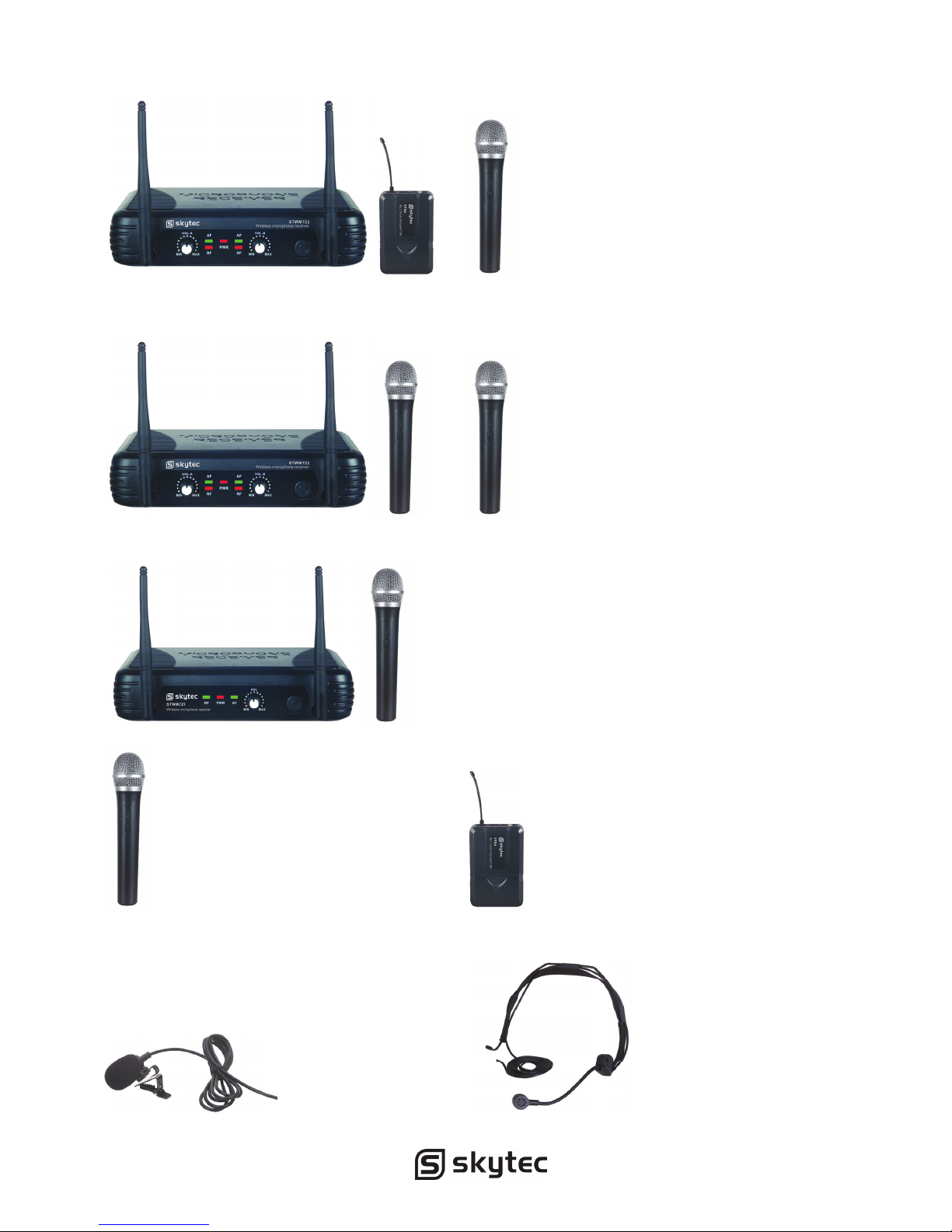
STWM722C 2CH COMBI RECEIVER (179.165)
STWM722 2CH RECEIVER (179.170)
STWM721 1CH DIVERSITY RECEIVER (179.175)
ACCESSORIES:
STM4 HANDHELD MICROPHONE (179.167) PDB3 BODYPACK (179.154)
PDT3 TIE CLIP MICROPHONE (179.158) PDH3 HEADSET (179.156)

UK
Thank you very much for purchasing this SKytec wireless microphone kit. Please read this
manual thoroughly before using this equipment
Warning
-
Always read the manual before using the product.
- Keep the manual so every new user can read it before using the product.
- Always keep the packaging. When a malfunction occurs, please send it in the original
packaging.
- Only for indoor use. Do not use in moistures places.
- Don’t expose to direct sunlight or heat sources.
- Don’t let small objects or fluids enter the housing. This may cause malfunction.
- Clean this unit with a dry cloth. Don’t use cleaning fluids or solvent.
- Unit contains no serviceable parts. Only the replacement parts named in this manual can
be changed by the user or servicing personnel.
- Never open the unit, service may only be done by qualified personnel.
- Never remove or place the mains plug in a socket with wet hands.
- Disconnect the unit from mains power before servicing.
- Condensation water can form while reusing, please let the unit reach the environmental
temperature before using it.
- Keep out of children’s reach.
- When the unit is damaged in a way that internal parts are visible. NEVER connect the unit
to a mains socket and NEVER switch the unit on. In this case, contact your supplier.
- When a lightning storm occurs, always disconnect this unit from the mains socket. Do the
same when the unit won’t or hasn’t be used for a long period of time.
- Using this unit might cause disturbance in insufficiently shielded equipment. This
disturbance might cause damage or accidents. Please check if there is any sensitive
equipment in close proximity of the unit before installing it.
To all residents of the European Union
Important environmental information about this product.
This symbol on the device or the package indicates that disposal of the device after its
lifecycle could harm the environment. Do not dispose the unit or batteries as unsorted
municipal waste, its should be taken to a specialized company or local recycling
service. If in doubt, contact your local waste disposal authorities.
SYSTEM FEATURES
All UHF Series systems offer a variety of exceptional features, including:
1. Multiple System Use: Up to several UHF systems can be used in the same performance
space. Each system must be set at a different frequency. (Frequency marked on the back
of the receiver)
2. Simultaneous Output Use: Unbalanced 6.3mm phone plug and balanced XLR output
connectors may be used simultaneously to different external devices.
3. Range: UHF Series transmitters will work at a distance of up to 50 meters from the
receiver.
4. Noise Squelch: Squelch circuit analyzes signal strength and quality so that can reduces
the likelihood of noise burst due to environmental RF (radio frequency) noise.
5. Low Battery Warning Light: A red light on the body-pack and hand -held transmitters
warns the user that there is less than one hour of battery life left.
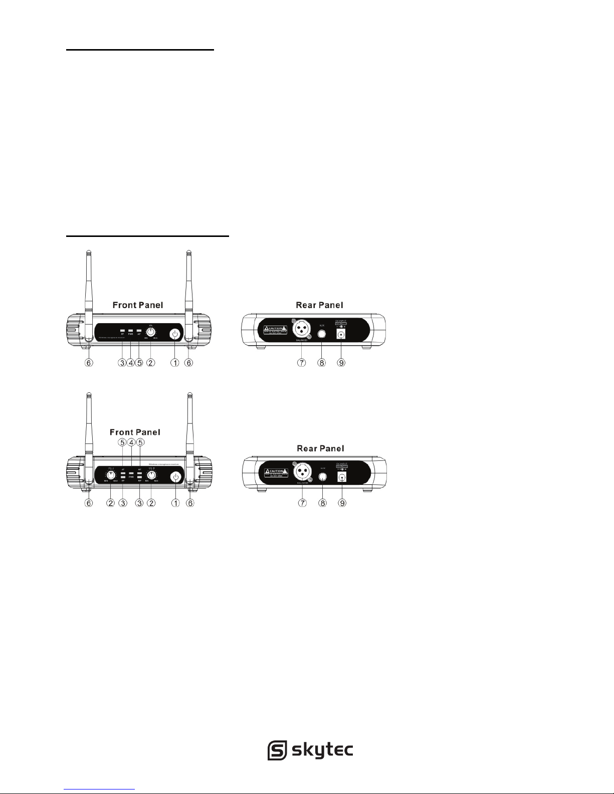
RECEIVER FEATURES
SINGLE CHANNEL RECEIVER
DUAL CHANNEL RECEIVER
1. Power Switch: Power ON/OFF the receiver.
2. Volume Knob: Adjust the volume output of receiver.
3. "RF" signal-lndicator:ltis glows when the Receiver receive RF signal from Transmitter.
4. Power Indicator: Indicate the power ON/OFF.
5. "AF"Audio Level Indicator: Indicate the wireless system audio signal level.
6. Antenna A/B.
7. XLR Balanced Output Jack: Connect the audio cable from this jack to the input port of
amplifier, mixer.
8. 6.3mm Audio Output Jack: Connect the audio cable from this jack to the input port of
amplifier, mixer.
9. Power Jack: Connect the AC/DC adapter to receiver.
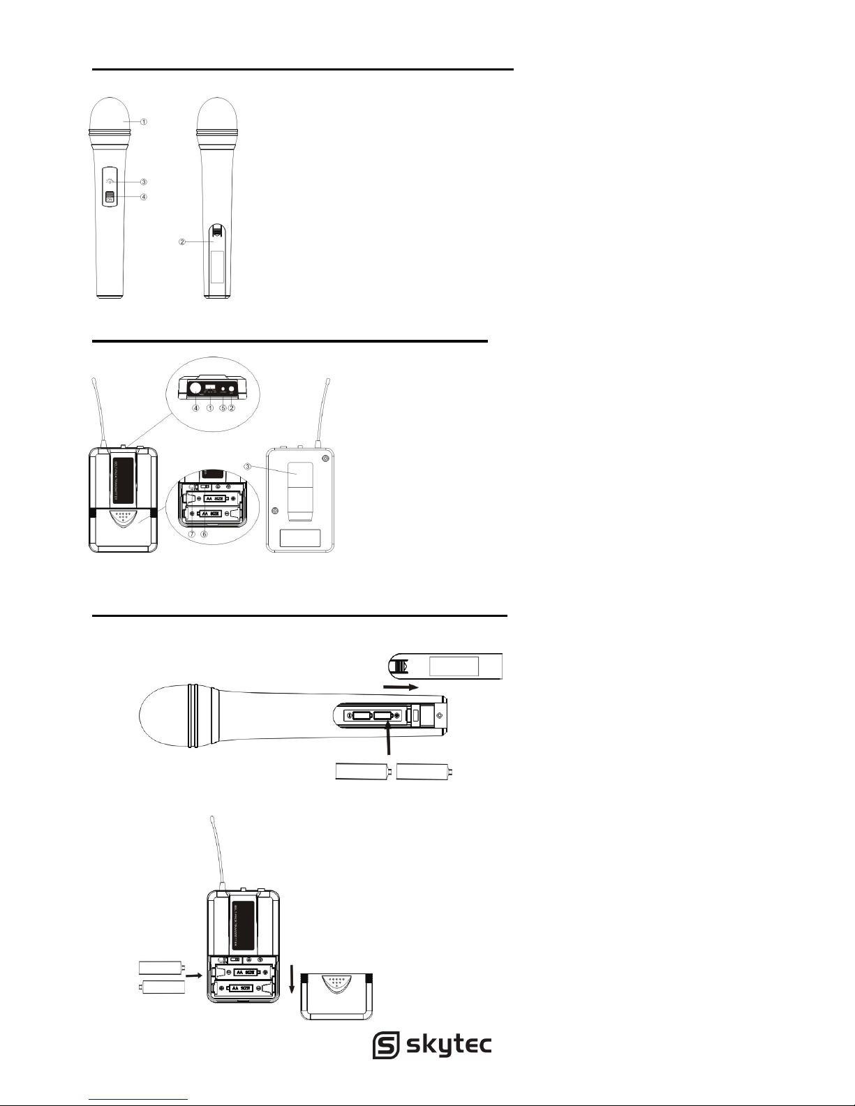
MICROPHONE-TRANSMITTER FEATURES
1. Grille: Protects the cartridge and help reducing the breath sounds
and wind noise.
2. Battery Cover: Open it to install the battery.
3. Low Battery Indicator: Red light glows when it is lack of power and
should Renew the battery.
4. Power and Audio Mute Switch.
BODY-PACK TRANSMITIER FEATURES
1. Power and Audio Mute Switch.
2. Antenna: Transmit the RF signal of transmitter.
3. Bell Clip: Allach the transmitter to the belt.
4. Audio Input Jack: it is suitable for lavaliere
system/headset system.
5. Low Battery Indicator: Red light glows when it is lack
of power and should renew the battery.
6. State Setting Switch: Set the using slate of lavaliere
system (L) / headset system(H).
7. Gain Adjusting Volume: Adjust the transmitter audio
input gain.
TRANSMITTER BATTERY INSTALLATION
1. Battery Installation of Handheld Microphone: Push open the battery cover, Insert the
supplied batteries into battery jar in polarity and cover the battery Cover.
2. Battery Installation of Body pack transmitter: Push open the battery cover, Insert the
supplied batteries into battery jar in polarity and close the battery cover.

BODYPACK TRANSMITTER CONNECTION
1. Lavaliere Microphone Connection: Connect the connecter of supplied. Lavaliere
microphone to the connecting jack of transmitter (Shown as below) Set the transmitter
work state in wireless lavaliere system.
2. Headset Microphone Connection: Connect the connecter of supplied Headset microphone
to the connecting jack of transmitter(Shown as below) Set the transmitter work state in
wireless head set system.
SYSTEM CONNECTION
1. Receiver Power Connection: Connect the DC connector of supplied AC/DC adapter into
the DC power input of receiver. Plug the AC input connecter into an 230~240VAC/50Hz
outlet. (Shown as below)
2. Antenna: Keep the position of antenna at a 45 angle from vertical, .(Shown as below)
3. Audio Connection: Connect the corresponding output of receiver by supplied 6.3mm
phone jack audio cable or your XLR cable to the input of power amplifier, mixer.

BODYPACK TRANSMITTER AUDIO GAIN ADJUSTMENT
The audio gain control on transmitter has been factory-at the mid-range position for best
performance in most applications. This may be necessary for soft singers or talkers, or guitar
or basses with low outputs.
• To Increase Gain: Rotate the transmitter gain control clockwise with the screwdriver to
increase audio gain.
• To Reduce Gain: Rotate the transmitter gain control counter clockwise with the
screwdriver to reduce audio gain.
• To return audio gain to the factory setting, rotate the transmitter audio gain control to
the mid position
TIPS FOR ACHIEVING MAXIMUM PERFORMANCE
• Make sure you can always see a receiver antenna from the transmitter position.
• Keep the distance from transmitter to receiver antenna as short as possible.
• Point receiver antennas away from each other at a 45 angle from vertical.
• Avoid placing the receiver antennas near metal surfaces and obstruction.
• Monitor battery fuel gauge and replace battery as soon as red light is on.
• If stacking or rack mounting receivers In a multiple-system use situation, do not allow
antennas to touch or cross.
• Perform a walk-through before Performance or Presentation .If dead spots are found,
adjust location of receiver .If dead sports remain ,mark spots and avoid.
TROUBLESHOOTING
PROBLEM INDICATOR STATUS SOLUTION
No sound
Red transmitter indicator is not
flash
Slide transmitter POWER ON/OFF switch to ON
Make sure battery is Inserted properly, observing battery
("+/."). If battery is inserted
properly. replace with fresh battery.
No sound Red transmitter indicator Is flash Slide transmitter MUTE/ON switch to ON position
No sound Red receiver POWER light off.
Make sure ac adapter is securely plugged into electrical
outlet and into de input connector. Make sure ac
electrical outlet works and supplies proper voltage.
No sound
Receiver signal Indicators A/B
lights glowing
Turn up receiver volume control. Confirm that the output
connections from the receiver to the external equipment
are secure.
No sound
Receiver signal Indicators A/B
lights off, Transmitter and
receiver POWER lights glowing
Confirm transmitter’s and receiver’s frequencies match.
Move transmitter closer to receiver
Sound level differs
from level of a
cabled instrument
Receiver signal Indicators A/B
lights glowing
Adjust transmitter gain level to compessary
Adjust receiver volume as necessary
Sound level differs
with different guitars
Receiver signal Indicators A/B
lights glowing
Readjust transmitter gain level to compensate for
differences In guitar outputs
Distortion level
increases gradually
Receiver Signal Indicators A/B
Lights and transmitter LOW
BATTERY light glowing
Replace transmitter battery
Bursts Of noise or
other audible radio
signals present
Signal Indicators A/B lights on
Identify potential sources of interference (other
RF·sources) and turn off, remove or use a wireless
system operating on a different frequency
Momentary loss of
sound as transmitter
is moved around.
performing area.
Receiver signal Indicators A/B
lights off when sound is lost
Reposition receiver and perform walkthrough test, if
audim dropouts persist mark "dead" spots and avoid
them during performance
 Loading...