

5 CHANNEL DJ MIXER TEC 250
172.890
Instruction Manual
Gebruiksaanwijzing
Mode d’Emploi
Gebrauchsanleitung
Brugsanvisning
LAYOUT
Front Panel / Voorzijde / Façade / Frontseite / Forside
Rear Panel / Achterzijde / Arrière / Rücksei te / Bagside

GB
Congratulations on the purchase of this SkyT ec mixer.
Please read this manual carefully prior to using the unit.
Warning:
- Read the manual prior to using the unit.
- Keep the manual for future reference.
- Keep the packaging for safer transport in its original pa ckaging
- For indoor use only.
- Prior to the first use, have the unit checked by a qualified person.
- The unit contains voltage carrying parts. DO NOT o pen the mixer.
- When you unplug the unit from the mains always pull the plug, n ever the lead.
- Never plug or unplug the unit with wet hands.
- If the plug and/or mains lead are damaged, they ne ed to be repaired by a qualified technici an.
- If the unit is damaged to an extent that you can se e intern al parts, do not plug the u nit into a ma ins outlet.
- Repairs and lamp replacement has to be carried o ut by a qualified tech nician.
- Only connect this unit to an earthed mains outlet of 230Vac/50Hz and 10-16A.
- Do no place the unit near heat sources.
- Always unplug the unit during a thunderstorm or when it is not in use.
- If the unit has not been used for a longer period of time, condensation can occur inside the housing.
Please let the unit reach room temperature prior to use.
- Keep out of the reach of children.
- All channel controls and the master volume cont rol must be set to zero pri or to switching th e unit on.
- To prevent clipping of the amplifier do not set th e volume level too hig h.
- Switch the amplifier on at latest and switch it off at first.
- Do not use cleaning sprays for the slider controls. The residues of these spray cause dust deposits in
the controls. If a problem occurs, please consult a spe cialist.
DESCRIPTION OF FEATURES
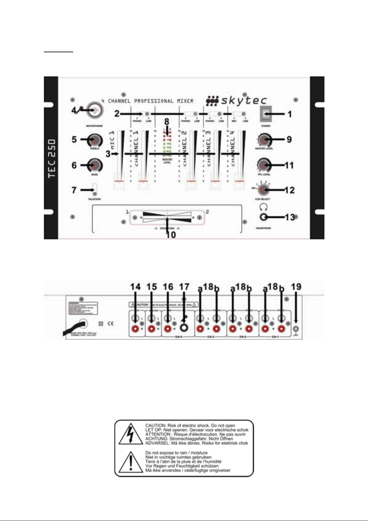
1. IEC socket Connection for the AC power supply
2. Input selector Switches the input of the channel between the line and pho no inputs.
3. Channel Controls the volume of each individual channel.
4. Microphone 6.3mm/XLR combi jack for a microphone
5. Treble Treble control for MIC
6. Bass Bass control for MIC
7. Talkover Switch that attenuates the sound of every channel when the mi c is used
8. VU Meter Accurately displays the output signal level.
9. Master Volume This control adjusts the overall output volu me.
10. Crossfader Used to fade smoot hly between ch annels 1 and 2. Easily replaced when required.
11. Cue Volume Controls the level of the volume in the headphones.
12. Cue Select Used to select the channel that i s monitored by the headph ones.
13. Headphone 6.3mm stereo jack socket, output for headphone monitoring.
14. REC RCA sockets for connection to a recorder
15. Stereo Outputs RCA (phono) sockets should be connected to the powe r input of your amplifie r.
16/18a. Line Inputs RCA (phono) sockets, inputs for line level inputs su ch as CD play ers and tape
players.
17. MIC 6.3mm Jack connector for the microphone
18b. Phono Inputs RCA (phono) sockets, inputs for turntables.
19 GND Earth terminal for grounding turntables.
INSTALLATION AND OPERATION
- Place the TEC250 on a suitable level surface.
- Connect your audio sources to the correct inputs, Lin e level to the line inputs a nd turntable to the phono
inputs. Although this mixer is only a 4 channel mixer it is po ssible to connect 7 devices to the in puts (one
microphone, three turntables and three line level devices such as CD players etc.) sele ction of the
equipment is by the Phono/Line switch. When con necting a turntable you will find a separate eart h lead
that should be connected to the GND terminal.

- Connect the output of the TEC250 to a suitable input of your amplifier usi ng the stereo RCA (phon o)
lead supplied. The input should be suitable for a li ne level signal an d will be marked LI NE, CD, AUX or
something similar.
- Connect the mains lead to the IEC socket on the rea r of the unit and conne ct to a suitable main s outlet.
- Before turning on the unit set all the volume controls at minimum both on the TEC250 an d on the
amplifier. Turn all your input devices on first with no signal playing then switch on the TEC250, the
amplifier should be turned on last. Starting this way avoi ds any large ‘p ops’ or other speaker dam aging
signals.
- Start your audio source playing and slowly rais e the channel volume co ntrol until the VU met er indicat or
starts to light, you may need to adjust the crossfader, this indicates that you have an output signal. T he
ideal setting is so that the level of the signal on the VU meter is around 0dB position. Next turn the
volume of the amplifier up. By adjusting the levels of the channel volum e and amplifier volu me you can
achieve your desired music level.
- With headphones connected you can monito r the input of either of the thre e channels reg ardless of the
position of the crossfader of individual channel vol ume. Press the cue b utton of the channel to hear it in
the headphones, the LED will light to show wh en the channe l is selected.
- The Cue pan control is used to move between no rmal and split cue. In no rmal cue mode the signal in
the headphones is what has been selecte d by the cue switch es. In Split Cue mo de the signal i n the
LEFT is the selected cue channel and the si gnal in the RIGHT i s the output of the mix er – this is
particularly useful when using the mixer without monitor speakers.
- The gain and Eq controls for each channel can be used to adj ust the sound fro m each channel to
correct any defects in the levels of the sign al for example a qui et signal ca n be made loud er or a too
‘bassy’ sound can be made less bassy.
- The crossfader is used to ‘fade’ between channels 1 and 2 when ‘ha rd left’ only chan nel 1 is passed to
the amplifier, similarly when ‘hard right’ only channel 1 is passed to the amplifier and when i n the middle
both signals are equally mixed.
- The microphone input has a small equaliser (Bass and Treble) to allow you t o adjust the sound of the
microphone. The microphone has its own volum e control to adjust the l evel of the signal.
REPLACEABLE CROSSFADER
- Even under normal operation the crossfader may be come worn or damaged d ue to frequent use/a buse.
Fortunately it is user replaceable (contact your SKYTEC retailer for suitable part) and requires no more
tools than a suitable Philips screwdriver.
- It is important to disconnect the unit from the mains supply befo re you begin.
- Remove the two large screws and lift the crossfader un it out of the mixer.
- The crossfader is connected by a non reversible conn ector that should b e easy to disconnect.
- Attach the new crossfader to the plug and replace in to the mixer with the connector facing upwards as
before to ensure that the crossfader is orientated correctly.
- Replace the two screws.
PRECAUTIONS
- Ensure that the AC power is off before making any connections.
- Don’t use any spray cleaners as residue will cause excessive dirt build up and damage the controls.
Under normal use slide controls will last for many years. Repairs or repla cement other then t hose
contained in this manual should be undert aken by a qualif ied professio nal technicia n.
- Use appropriate cables.
- Turn amps on last and off first – this will reduce transients that may cause speaker damage.
- Repeated ‘banging’ of the controls against their physical limits can cause damage.
- When all LEDs of the VU meter are lit (including th e red) the output si gnal is trying to ri se above the
capacity of the mixers output and will result in si gnal ‘clipping’ and distortion. T his in turn will be
overloading the input of your amplifier and may cause damage.
Do not attempt to make any repairs yourself. This would invalid your warranty.
Do not make any changes to the unit. This would also invalid your warranty.
The warranty is not applicable in case of accidents or damages caused by inappropriate use or disrespect of the warnings
contained in this manual.
SkyTronic UK cannot be held responsible for personal injuries caused by a disrespect of the safety recommendations and
warnings. This is also applicable to all damages in whatever form.

F
Nous vous remercions pour l’achat de cette table d e mixage SkyTe c
Lisez attentivement ce manuel avant la première mise en service.
Consignes de sécurité:
- Lire le mode d’emploi avant la première mise en servi ce.
- Conservez le mode d’emploi pour référenc e ultérieure.
- Conservez l’emballage d’origine afin de pouvoir transporte r l’appareil en toute sécurité.
- Uniquement pour utilisation à l’intérieur.
- Ne pas ouvrir le boîtier. Il contient des pièces sous tension.
- Pour débrancher, tirer toujours sur la fiche, jamais sur le cordon.
- Ne pas brancher ou débrancher l’ appareil avec de s mains m ouillées.
- Si la table de mixage est endommagée, ne la branchez pas sur une prise secteur et ne la mettez pas
sous tension.
- Si la fiche et/ou le cordon secteur sont endommagés, faites-les remplacer par un spéciali ste.
- Branchez la table de mixage uniquement sur une prise de terre de 230Vac/50Hz d’une intensité de 1016A.
- Ne pas placer la table de mixage à proxi mité d’une sour ce de chaleu r.
- Pendant un orage ou en cas de non-utilisation, d ébranchez touj ours l’appareil d u secteur.
- Après une période de non-utilisation prolongée, de l’eau de condensation a pu se former. Attendez que
la table de mixage ait atteinte la température ambiant e.
- Tenir hors de la portée des enfants.
- Lorsque la table est mise sous tension, veillez à ce que tous les canaux et le volume général soient
réglés sur le minimum.
- Manipulez les contrôles de canaux avec précaution. Une variation rapide risque d’endommager les
haut-parleurs suite à un clipping de l ’amplificat eur.
- Eviter un clipping de l’amplificateur. Ceci se produit lorsque les LED de clipping sur l’amplificateur
s’allument. Réglez le volume de façon à ce que ceci ne p uisse pas se produire.
- Allumez l’amplificateur toujours en dernier et éteignez-le e n premier.
- N’utilisez pas de sprays pour nettoyer les potentiomètres. Les résidus de ces sprays provoquent des
dépôts de poussière et de graisse. Consultez un spécialiste en cas de probl ème.
DESCRIPTION DES FONCTIONS
1. Fiche IEC Connexion du cordon d’alimentation.
2. Input selector Commute l’entrée du canal entre les éntrées pho no et ligne.
3. Volume du canal Règle le volume individuel de chaque ca nal.
4. MIC Connecteur combiné jack 6,3/XLR pour un micro
5. TREBLE Réglage des aigus
6. BASS Réglage des graves
7. TALKOVER Atténue le volume des canaux si le micro est utili sé
8. VU-mètre Affiche avec précision le niveau du signal de sortie.
9. Volume général Ce contrôle règle le volume de sortie général.
10. Crossfader Permet de bascul er progressivement ent re les canaux A et B.
Remplacement rapide.
11. Volume Cue Règle le niveau de pré-écoute dans le casque.
12. Cue Select Permet de sélectioner le canal qui est pré-écouté dans le casque.
13. Casque Jack femelle stéréo 6,35mm pou r la sortie ca sque.
14. REC Fiches RCA pour un appareil d’enregistre ment
15. Sorties stéréo Fiches RCA femelles à brancher sur l’entrée de votre amplificateu r.
16/18a Entrées ligne Entrées RCA femelles pour des appareils de niveau ligne tels que des
lecteurs CD et enregistreurs.
17. MIC Jack 6,3mm pour le microphone
18b. Entrées phono Entrées RCA femelles pour platines-disques.
19 GND Cosse de masse pour la mise à la masse de platin es-disques.
INSTALLATION ET FUNCTIONEMENT
- Posez la table de mixage sur une surface stable et pla ne.

- Connectez vous sources audio aux entrées correspondates. Les équipment de niveau ligne aux entrées
ligne et les platines-disques aux entrées phono. Bien qu e cette table de mixage n e dispose que de 5
canaux, il est possible de connecter 9 appareils a ux entrées (deux micros, troi s platines et quatre
appareils de niveau ligne tels des lecteurs CD, et c.) La sélectio n de l’équipment souhaité se fait au
moyen du commutateur Phono/Line. Lorsque vous co nnectez une pl atine-disque s, vous devez
égalemant effecteur la mise à la masse sur la co sse GND.
- Branchez la sortie de la table de mixage à l’éntrée corre spondante de votre amplificateur au moyen de
cordon RCA stéréo (phono) fourni. L’éntrée dev rait couveni r à un signal de niveau ligne et sera re péré
par LINE, CD, AUX ou similaire.
- Connectez le cordon secteur à la fiche IE C au dos de l a table de mix age et à une pri se secteur.
- Avant la mise sous tension de la table de mixage, régle z tous les contrôl es de volume sur le minimum,
aussi bien sur le TEC250 que sur l’am plificateur. Mette z d’abord vos source s d’entrée sou s tension sans
la présence d’un signal. Allumez ensuite le TEC250 et l’amplificat eur en dernier. Ai nsi vous éviterez de
grands bruits qui risquent d’endommager les hauts-parleurs.
- Commencez la lecture de votre source audio et au gmentez lente ment le contrôle d e volume du canal
jusqu’à ce que le VU-mètre s’allume. Il sera éventuellement nécessaire d’adjuster le crossfader. Ceci
indique la présence d’un signal autour de 0dB sur l e VU-mètre. Augmentez ensuite le volume de
l’amplificatuer. En réglant les niveaux de volume du canal et de l’amplificateu r vous arriverez a u niveau
de musique désiré.
- Lorsqu’un casque est branché, vous pouvez pré-écouter l’entré e de l’un des t rois can aux, quelque soit
la position du crossfader ou du volume indi viduel du canal. Tou rnez le bouton Cue Sel ect sur le cana l
désiré afin de l’entendre dans le casque.
- Le crossfader sert à basculer << en fo ndu>> entre le s deux canaux. En po sition complète ment à
gauche, seul le canal 1 est achiminé vers l’amplificateur. En po sition centrale, le s deux sig naux sont
mélangés à parts égales.
- L’entrée micro possède un petit égaliseur (graves et aigus) afin de vous permettre d’adjuster le son du
micro. Le micro dispose de son propre cont rôle de volum e pour ajuster le niveau de signa l. Lorsque le
commutateur de Talkover est activé, le niveau de so rtie de tous les ca naux à l’excep tion du canal micro
est réduit afin d’entendre plus clairement la voix.
REMPLACEMENT DU CROSSFADER
- Même lors d’une utilisation normale, le crossfade r peut s’user ou être e ndommagé en rai son d’une
utilisation fréquente. Heureusement il est remplaçable par l’utilisat eur (contactez votre rev enduer
SKYTEC pour les pièces apporpriées) et ne nécessite pas d’autres outils qu’un tournives cruciforme.
- Il est impératif de débrancher la talbe de mixage du se cteur avant de co mmencer le remplacem ent.
- Retirez les deux grandes vis et sortez le crossfader d e la table de mixage.
- Le crossfader est connecté à une fiche non réversible qui est facile à débrancher.
- Enfiches le nouveau crossfader sur le connectuer et rem ettez-le dans la tabl e de mixage ave c le
connecteur orienté vers le haut comme à l’origine afin d’être sûr de sa bonne position.
- Remettez les deux vis en place.
PRECAUTIONS
- Assurez-vous que le courant est coupé av ant d’effecteur de s connexions.
- Ne pas utiliser d’aérosols de nettoyage puisque l es résidus favo riseront la formation excessive de
poussière et endommageront les contrôles. Avec une utilisation normale, les porentiomètres ont une
durée de vie de plusiers années. Des répa rations ou remplace ments autres que ceux mentionn és dans
ce manuel devront être confiés à une technicien qualifi é.
- Utilisex des cables appropriés.
- Allumez les amplificateurs en dernier et éti guez-les en premier. Ceci ré duira les transitoires qu e risquent
d’endommager les haut-parleurs.
- Ne <<tapez>> pas les contrôles contre leu rs butoirs sou s peine de les endommager.
- Lorsque toutes les LEDs du VU-mètre sont allumées (y compri s le rouge), le signal de so rtie essaie de
dépasser la capacité de sortie de la table de mix age. Le résultat se ra le <<clipping>> et u ne distorsio n
du signal. Ceci surchargera l’entrée de v otre amplificateu r et risque de causer des dommage s.
N’effectuez jamais de réparations vous-même et n’apportez jamais de modifications sous peine d’invalider la garantie.
La garantie ne s’applique pas dans le cas de dommages sous quelque forme que ce soit, qui ont été provoqués suite à une
mauvaise utilisation et le non-respect des avertissements et consignes de sécurité contenus dans ce manuel.
SkyTronic décline toute responsabilité en cas de dommages corporels suite au non-respect des consignes de sécurité et des
avertissements. Ceci s’applique aussi aux préjudices ultérieurs éventuels.

D
Herzlichen Glückwunsch zum Kauf dieses SkyTec Mischpults.
Bitte lesen Sie diese Anleitung sorgfältig vor d er Inbetriebna hme durch.
Sicherheitsvorschriften:
- Bedienungsanleitung vor Inbetriebnahme sorgfältig durch lesen.
- Für spätere Bezugnahme aufbewahren.
- Originalverpackung für späteren Transport aufb ewahren.
- Nur für Innengebrauch.
- Niemals das Gehäuse öffnen; Reparaturen n ur von einem F achmann ausfüh ren lassen.
- Beim Abziehen des Steckers immer am Stecker zi ehen, niemal s an der Netzschnur.
- Stecker niemals mit nassen Händen anfassen.
- Sollten Stecker und/oder Netzschnur, sowie der Kabeleingang zum Gerät beschädigt sein, müssen
diese durch einen Fachmann ersetzt werden.
- Wenn das Gerät sichtbare Schäden aufweist, darf es NICHT an eine Steckdose angeschlossen und
NICHT eingeschaltet werden. Benachrichtigen sie in diesem Fall SkyTronic BV.
- Das Gerät nur an eine geerdete 230V AC/50 Hz Netzsteckdose mit 1 0-16A Leistun g anschließen.
- Nicht in der Nähe von Wärmequellen auf stellen.
- Bei Unwetter sowie Nichtgebrauch das Netzgerät aus der Steckdose ziehen.
- Nach längerem Nichtgebrauch kann sich Kondenswasser im Gehäuse gebildet haben. Lassen Sie das
Gerät erst auf Raumtemperatur kommen.
- Vor Kindern schützen.
- Vor dem Einschalten alle Kanalschieberegle r, sowie den Master L autstärkere gler ganz herunterf ahren.
- Die Schieberegler vorsichtig behandeln. Eine zu schnelle Veränderung kann die Lautsprecher
beschädigen, weil der Verstärker überfordert ist.
- Den Verstärker nicht überfordern (Clipping). Wenn die Clip LEDS am Verstärker aufleuchten, ist die
Lautstärke zu hoch eingestellt. Sofort die Laut stärke auf ein en niedrige rn Pegel einstelle n.
- Den Verstärker immer zuletzt einschalten und zuerst a usschalten.
- Keine Reinigungssprays für die Schieberegler verwenden. Die Rückstände verursachen Schmier- und
Staubansammlungen in den Reglern. Im Problemfall einen Fachmann fragen.
FUNKTIONSBESCHREIBUNG
1. IEC Buchse Anschluß für das Netzkabel.
2. Input selector Schaltet den Kanaleingang zwischen Phono und Line um.
3. Kanallautstärke Regelt die Lautstärke jedes einzelnen Kanals.
4. MIC Kombinierte 6,3mm/XLR Buchse zum Anschluss eine s Mikrofons
5. TREBLE Hoher Klangregler für beide Kanäle
6. BASS Tiefer Klangregler für beide Kanäle
7. TALK OVER Übersprechdämpfung
8. VU-Meter Zeigt genau den Ausgangssignalpagel an.
9. Master-Lautstärke Regelt die Gesamtlautstärke des Mischpults.
10. Crossfader Zum weichen Umblenden zwischen Kanal A und B. Lei cht austauschbar.
11. Cue Lautstärke Regelt die Lautstärke im Kopfhörer.
12. Cue Select Wählt den Kanal, der über die Kopfhörer vorgehört werden soll.
13. Kopfhörer 6,35mm Stereo-Buchse, Kopfhörerans chlußbuchse.
14. REC Cinch Anschluss für einen Recorder
15. Stereo-Ausgänge Cinch-buchsen zum anschluß an den verst ärkereingang.
16/18a Line-Eingänge Cinch-buchsen zum Anschluß von Line-Pegel-Geräten wie CD Spi elern
und Kassettenrekordern.
17. MIC 6.3mm Klinkenbuchse für ein Mikrofon
18b. Phono-Eingänge Cinch-Buchsen für Plattenspieler.
19 GND Masseanschluß für Plattenspieler.
EINBAU UND BEDIENUNG
- Stellen Sie den TEC250 auf eine flache, feste Fläche.
- Schließen Sie die Audioquellen an die entsprechend en eingänge: Line-Pege l-Geräte an Line-Eing änge
und Plattensplieler an die Phono-eingänge. Obwo hl dies ein 5-Kanal-Mi schpult ist, können 9 Geräte an
die Eingänge angeschlossen werden (zwei Mikrofone, drie Plattenspiele r und vier Line-Pegel-Ge räte

wie z.B. CD Spieler usw.). Die angeschlossenen Geräte werden vom Phono/Line Schalter ausgewählt.
Beim Anschluß eines Plattenspielers muß das separate Massekabel an den GND Verbinder
angeschlossen werden.
- Den Ausgang des TEC250 mit dem mitge lieferten Stereo-Cinch -Kabel an einen g eeigneten Eing ang
anschließen. Der Eingang muß für eine Line -Pegel Signal gee ignet sein und ist du rch LINE, CD, AUX
o.ä. gekennzeichnet.
- Stecken Sie das Netzkabel in die IEC Buchse auf de r Rückseite des Gerät s, sowie an eine geeignete
Netzsteckdose.
- Bevor Sie das Gerät einschalten, stellen Sie all e Regler aufs Mini mum, sowohl am TEC250 als auch am
Verstärker. Zuerst alle Eingangsgeräte einschalten, ohne da ß ein Signal anliegt, da nn den TEC25 0
einschalten und zuletzt den verstärker. Auf diese Wei se werden laute Geräusch e vermieden, die di e
Lautsprecher beschädigen können.
- Spielen Sie die Audioquelle ab und erhöhe n Sie allmählich de n Kanallautst ärkeregler, bis da s VU-meter
beginnt aufzuleuchten. Diese bede utet, daß ein Au sgangssignal anli egt. Eventuell muß de r Crossfa der
eingestellt werden. Die ideale Einstellung ist errreicht, wenn das Si gnal auf dem VU-Meter um die 0dB
anzeigt. Stellen Sie als nächstes die Lautstärke des Verstärkers hoch. Durch ein Abstimmen der P egel
der Kanal- und Verstärkerlautstärke können Sie de n gewünschten M usikpegel errei chen.
- Wenn Kopfhörer angeschlossen sind, kön nen Sie einen d er drei Kanäle abhören, egal in wel cher
Stellung der Crossfade roder der Kanallaut stärkeregle r steht. Drehen Si e den Cue Select Re gler auf
den gewünschten Kanal.
- Mit dem Crossfader wird zwischen zwei Kanäl en umgeblendet. In d er ganz linken Stel lung wird nur
Kanal 1 in den Verstärker gespeist, in der ganz rechten Stellung nur Kanal 2. In der mittleren Stellung
werden beide Signale in gleichen M aße gemischt.
- Der Mikrofoneingang besitzt ein en kleinen Equalizer (B ass und Tre ble), um den Klang de s Mikrofons
einstellen zu können. Das Mikrofon verfügt über seinen ei genen Lautst ärkeregle r, um den Signalpeg el
einstellen zu können. Wenn der Übersprechschalt er (Talkov er) aktiviert wird, we rden alle
Ausgangssignalpegel herabgefahren, damit die Stimme deutlicher zu hören ist.
AUSWECHSELN DES CROSSFADERS
- Auch bei normalem Betrieb nutzt sich der Crossfader ab. Deshalb kann er vom Bediener sehr leicht
ausgewechselt warden (Ersatzteile erhalten Sie bei Ihrem SKYTEC Händler). Dazu benötigt man nur
einem Kreuzschraubendreher.
- Bevor Sie den Crossfader entfernen, muß das Mi schpult unbedi ngt ausgescha ltet und der Stecker
abgezogen werden.
- Entferenen Sie die beiden grossen Schrauben un d entnehmen Sie de n Crossfader.
- Der Crossfader ist an einen nicht umkehrbaren Ve rbinder angeschlo ssen, der einfach ze ent koppeln ist.
- Stecken Sie den neuen Crossfader in den Verbin der und setzen Sie i hn so ins Mi schpult ein, daß der
Verbinder nach oben zeigt, damit der Crossfader richtig herum eingesetzt wird.
- Drehen Sie die beiden Schrauben wied er fest.
VORSICHTMASSNAHMEN
- Netzstecker abziehen bevor Sie irgenswelch e Anschlüsse vornehmen.
- Keine Reinigungssprays benutzen, da die Rückstände d ie Bildung von Staub förde rn und die Regl er
beschädigen. Bei normalem Gebrauch halten die S cheiberegler viele Jahre. Reparat uren oder
Auswechseln von Teilen, die nicht ausdrücklich in die ser Anleitung besch rieben sind, dürfen nur von
einem qualifizierten Techniker vorgenom mern werden.
- Achten Sie darauf, nur geeignete Kabel zu verwe rnden.
- Die Verstärker müssen als Letztes eingeschaltet und als Erstes a usgeschaltet werd en, damit die
Lautsprecher nicht durch plötzliche Geräusch e beschädigt werden.
- Die Regler nicht an den Anschlag “knalle n”, um sie nicht zu beschädigen.
- Wenn alle LEDs des VU-Meters leuchten (auch die rote), ge ht das Ausg angssignal übe r die Kapazität
des Mischpults hinaus, was zu “Clipping ” und Verzerru ng des Signals f ührt. Das wied erum fürht zu
Überlastung des Verstärkers und kann S chäden ve rursachen.
Reparieren Sie das Gerät niemals selbst und nehmen Sie niemals eigenmächtig Veränderungen am Gerät vor. Sie verlieren
dadurch den Garantieanspruch.
Der Garantieanspruch verfällt ebenfalls bei Unfällen und Schäden in jeglicher Form, die durch unsachgemäßen Gebrauch und
Nichtbeachtung der Warnungen und Sicherheitshinweise in dieser Anleitung entstanden sind.
SkyTronic BV ist in keinem Fall verantwortlich für persönliche Schäden in Folge von Nichtbeachtung der Sicherheitsvorschriften
und Warnungen. Dies gilt auch für Folgeschäden jeglicher Form.

NL
Hartelijk dank voor de aanschaf van onze Skytec mengpaneel.
Lees deze gebruiksaanwijzing a andachtig doo r alvorens het apparaat i n bedrijf te stellen.
WAARSCHUWING:
- Lees altijd eerst de gebruiksaanwijzing voordat u een apparaat gaat ge bruiken.
- Bewaar de handleiding zodat elke gebruiker he m eerst kan doorle zen.
- Bewaar de verpakking zodat u indien het apparaat defect is, dit in de originele ve rpakking kunt opst uren
om beschadigingen te voorkomen.
- Alleen voor gebruik binnenshuis.
- Voordat het apparaat in werking wordt gesteld, altijd eerst een de skundige raadple gen.
- In het apparaat bevinden zich onder spanning staande onderdel en; open daarom NOOIT dit apparaat.
- Bij het verwijderen van de stekker uit het stopcontact noo it aan het netsnoer tre kken.
- Verwijder of plaats een stekker nooit met natte h anden resp. uit en i n het stopcont act.
- Indien de stekker en/of netsnoer als snoeringang in het apparaat beschadigd zijn dient dit door een
vakman hersteld te worden.
- Indien het apparaat zo beschadigd is dat inwendige (onder)delen zichtbaar zijn mag de stekker NOOIT
in het stopcontact worden geplaatst én het apparaat NOOIT worden ingeschakeld. Neem in dit geval
contact op met Skytronic BV.
- Reparatie aan het apparaat dient te geschieden doo r resp. een vakman en ee n deskundige.
- Sluit het apparaat alléén aan op een 230Vac/50Hz geaard stopcontact, verb onden met een 10-16A
meterkastgroep.
- Toestel niet opstellen in de buurt van warmte bronnen zoals verwarming et c.
- Bij onweer altijd de stekker uit het stopcontact halen, zo ook wanneer het apparaat een poos niet
gebruikt wordt.
- Bij he rgebruik kan condensatiewater gevormd worden; laat het apparaat eerst op kamertempera tuur
komen.
- Om ongevallen in bedrijven te voorkomen moét rekening worden gehouden met de daarvoor geldende
richtlijnen en moeten de aanwijzin gen/waarschu wingen worden gevolgd.
- Het apparaat buiten bereik van kinderen houden.
- Zorg er altijd voor dat wanneer het apparaat wordt ingeschakeld dat alle kanaalschuiven en het
mastervolume op minimaal staan.
- Regel de kanaalschuiven met beleid, snelle variati e kunnen de l uidsprekers beschadi gen doorat de
versterker gaat clippen.
- Zorg ervoor dat de versterker nooit gaat clippen: Dit gebeurt wanneer de clip leds, meestal op het front
van de versterker, opgaan lichten. Regel het volume dusdanig i n dat dit niet gebeu rt.
- Schakel een versterker altijd als laatste aan en schakelt hem als e erste uit.
- Gebruik geen schoonmaak spray om de schuifregelaars te reinigen. Restanten van deze spray
veroorzaken dat smeer en stof ophopen in de regelaar s. Bij storing raa dpleeg een de skundige.
OMSCHRIJVING VAN DE DIVERSE FUNCTIES
1 Power Aan/uitschakelaar.
2 Input selector Schakelt de ingang van het betreffende kanaal tussen phono en line.
3 Channel volume Voor de volumeregeli ng van de separate kan alen.
4 Microphone XLR combi Jackplug aansluiting voor de microfoon
5 Treble Hoge tonenregeling voor Mic1
6 Bass Lage tonenregeling voor Mic1
7 Talkover Schakelaar om het geluid van het kanaal teru g te regelen ten behoeve van
microfoongebruik
8 LED VU-meter Nauwkeurige weergave van het uitgangsniveau.
9 Master volume Regeling van het totale uitgangssi gnaal.
10 Crossfader Voor soepele overgang tussen de signalen van kanaal 1 en 2.
11 CUE volume Regeling geluidsniveau van de voorafluiste ring.
12 CUE select Kanaalsectie voorafluistering.
13 Headphone 6,35mm stereo jack-contra, voor het aansluiten van een hoofdtelefoon.
14 Rec RCA-contra aansluitingen voor naar een opnameapparaat
15 Stereo output RCA-contra, voor doorvoer van het signaal naar de versterker.

16/18a Line inputs RCA-contra, ingang voor lijnsignaal, bijv. Cd-spelers, tapedecks en minidisc
spelers.
17 Mic 6.35mm Jack aansluiting voor het aansluiten van een mi crofoon
18b Phono inputs RCA-contra, ingang voor draaitafels.
19 GND Aardaansluiting voor draaitafels.
INSTALLATIE EN GEBRUIK
- Plaats de mengtafel op een geschikte ond ergrond
- Sluit uw audiobronnen aan op de daarvoor bestemde ingang en. Het is mogelij k om 9 audio bronnen aan
te sluiten (3 draaitafels, 4 lijnsignalen en 2 microf oons). Bronselecti e vindt plaats m.b.v. de phono/line
schakelaar. Bij het aansluiten van platenspelers, de aa nwezige aard draad aansluiten op de GNDconnector.
- Sluit de mengtafel aan op een geschikte ei ndversterker met de bijgele verde RCA -kabel. De ingan g van
de versterker moet geschikt zijn voor lijnsignalen.
- Sluit de netspanning aan. Voor het aanschakelen v an de mengtafel di ent u alle volumeregel aars op de
minimale stand te zetten, inclusief de eindversterke r. Dit voorkomt scha de aan uw appa ratuur bij
eventuele overstuur.
- Start uw audiobron en regel de volumes dusdanig totdat de LED VU-meter begi nt op te lichten. U heeft
nu een uitgangssignaal, de ideale volumestand va n de mengtafel is e en maximale uitslag ro nd de 0 dB
positie. Draai nu langzaam het volume van de versterke r omhoog, m.b.v. het ch annel volume en
versterker volume stelt u het volume in op het gewenste niveau.
- Via de hoofdtelefoonaansluiting kunt u, ona fhankelijk van de stand van de kanal en, de kanalen
voorafluisteren. Het gewenste kanaal kan geselecteerd worden met de CUE-sel ect schakelaar.
- De crossfader verzorgt de soepele overga ng tussen de beide signalen van de aa ngesloten
audiobronnen. In de meest linkse stand wordt kana al A volledig doorgegeve n, in de meest recht se
stand kanaal B. In de middenstand worden bei de signal en even ste rk doorgegeven.
- De microfooningang is voorzien van een bas e n treble regeling om uw signaal aan te passen aan uw
wensen. De talkover schakelaar, indien ingeschakeld, zorgt ervoor dat alle andere signalen gedempt
worden opdat de microfoon voldoende duidelijk hoorbaa r is.
VERVANGEN CROSSFADER
- door een veelvuldig gebruik van de crossf ader kan h et voorkomen dat deze ve rsleten of defect raa kt.
De crossfader is zodanig gemont eerd dat deze zeer eenvoudi g te vervang en is (neem conta ct op met
uw SKYTEC dealer).
WAARSCHUWINGEN
- Verzeker u ervan dat de netspanning is uit geschakeld al s u verbindingen g aat maken of wi jzigen.
- Gebruik de juiste aansluitkabels voor de specifieke sign alen.
- Zorg er altijd voor dat de versterker als laatste wordt inges chakeld en als e erste wordt uitges chakeld. Dit
voorkomt schade aan uw apparatuur bij eventuele overstu ur.
- Gebruik van reinigingsmiddelen en smee rmiddelen is niet toe gestaan, die ka n ernstige scha de
toebrengen aan de onderdelen.
- Eventuele reparaties altijd laten uitvoe ren doo r een SKY TEC ge autorisee rde de aler o f techni sche di enst.
- Voorkom overmatige mechanische belasting van de onderdel en.
- Indien de LED VU-meter zich continu in de rode zo ne bevindt is het uit gangssigna al overstuurd.
Vervorming is het resultaat, verlaagd u het ma stervolume tot een a cceptabel nivea u om schade aa n uw
apparatuur door overstuur te voorkomen.
Voer zelf geen reparaties uit aan het apparaat; in élk geval vervalt de totale garantie.
Ook mag het apparaat niet eigenmachtig worden gemodificeerd, ook in dit geval vervalt de totale garantie.
Ook vervalt de garantie bij ongevallen en beschadigingen in élke vorm t.g.v. onoordeelkundig gebruik en het niet in achtnemen
van de waarschuwingen in het algemeen en gestelde in deze gebruiksaanwijzing.
Tevens aanvaardt Skytronic BV geen enkele aansprakelijkheid in geval van persoonlijke ongelukken als gevolg van het niet
naleven van veiligheidsinstructies en waarschuwingen. Dit geldt ook voor gevolgschade in wélke vorm dan ook.

DK
Tillykke med købet af denne SkyTec audio mixerpult. Læs venligst vejledningen grundigt inden ibrugtagning.
ADVARSLER
- Læs vejledningen grundigt inden apparatet tages i a nvendelse
- Gem vejledningen til senere brug
- Gem emballagen hvis apparatet skal transport eres eller indse ndes til service
- Apparatet må kun anvendes indendørs
- Da dette apparat indeholder højspændings dele, er det forbundet med livsfare at åbne/adskille dette.
Overlad denne opgave til et autoriseret serviceværkst ed.
- Når lysnetkablet skal udtages, tag da fat omkrin g selve stikpro ppen – aldrig i kablet.
- Hvis lysnetkablet/stikproppen er beskadiget, må dette ikke tilsluttes stikkontakten
- Apparatet må kun tilsluttes en lovlig el-installation 230V ac/10A.
- Hvis apparatet har været transporteret udendørs, skal dette op bevares ved stuet emperatur i ca. 1 time
INDEN tilslutning, p.g.a. risiko for konden s.
- Apparatet må ikke placeres i nærheden af varme, kulde og fu gt.
- Alle kanaler og reguleringer skal være skruet ned p å minimum INDEN apparatet tæ ndes.
- Undgå overstyring og forvrængning, da dette kan ødelæg ge højttalerne.
- Ved rengøring, benyt da kun en fugtig klud. Aldrig kemikal ier eller rengø ringsmidler.
BESKRIVELSE AF FEATURES
1. IEC bøsning Tilslutning for AC netspænding (230Vac/50Hz).
2. Omskifter Vælger om kanalen skal tilsluttes grammofon eller lini esignal.
3. Kanal lydstyrke Kontrollerer lydstyrken individuelt på hver kanal.
4. MIC Kombineret 6.3mm jack/XLR bøsning for tilslutning af mikrofon
5. TREBLE Diskant regulering
6. BASS Bas regulering
7. TALK OVER Omskifter for automatisk dæmpning ved tale i mikrofonen
8. VU meter Viser udgangssignalet på mixeren.
9. Master volume Til justering af mixerens samlede udgangsniveau.
10. Crossfader Benyttes til smidig overgang mellem kanal A og B. Kan nemt udskiftes når
der bliver nødvendigt.
11. Cue volume Til justering af hovedtelefonens lydstyrke.
12. Cue select Benyttes til at vælge den kanal der skal aflyttes I hovedtelefonen.
13. Hovedtelefon 6.3mm stereo jackbøsning for tilslutning af hovedtelefon (monitor)
14. REC RCA phonobøsninger til optage-apparat (MD/Kassett e)
15. Stereo udgange RCA (phono) bøsnigner, der tilsluttes indgangen på effektforstærkeren.
16/18a Line indgange RCA (phono) bøsninger, der tilsluttes apparater med liniesignal udga ng,
f.eks. CD-afspiller, tuner, Minidisc, DAT båndoptager etc.
17. MIC 6.3mm mono jackbøsning for tilslutning af mikrofon
18b. Phono indgange RCA (phono) bøsninger, der tilsluttes udgangen fra grammofoner.
19 GND Stelterminal til jordforbinsele af grammafoner.
INSTALLATION OG DRIFT
- Placer TEC250 på en plen overflade
- Tilslut audiosignalerne til de korrekte indgangsbøsninger. Liniesignaler til linieindgange, og
grammofoner til phono indgangene. Selvom TEC250 kun er en 5-kanals mixer, er de t muligt at tilslutte 3
grammofoner, 2 mikrofon og 4 liniesignaler permanent. Der vælg es så indgang skilde via Phono/ Line
omskifterne. Ved tilslutning af grammofon, skal stelpu nktet (GND) også tilslutt es for at undgå brum.
- Tilslut udgangen på TEC250 til indgangsbøsningerne på effektforstærkeren. Benyt en stereo
phonoledning. Indgangen på forstærkeren kan f.e ks. være mærket med CD, AUX eller lign.
- Tilslut netkablet til IEC bøsningen, og tænd for stikkontakten.
- Inden mixeren tændes, sørg for at ALLE kont roller er skruet helt ned. Både på mixe ren og på
effektforstærkeren. Dermed ungås “knald” i højttalerne.

- Start signalkilden på et af de tilsluttede apparater, f.eks. e n CD. Skrue lagsomt op for skydef aderen på
den valgte kanal. Crossfaderen skal stå i midte rposition. Skrue l angsomt op for Mast er lydstyrken. Det
ideele niveau er opnået, når VU-meteret er ca. i 0 dB position.
- Via den tilsluttede hovedtelefon kan de 3 signalkilder aflyttes individuelt eller samtidig. Lydstyrken til
hovedtelefonen vælges via kontrollen mærket Cue-level.
- Crossfaderen benyttes til et smidigt og nemt mix mellem kanal A og B. I midte rposition vil begge kanal er
kunne høres, og afhængig af positionen m od A eller B regulere s lydniveauet (balancen ) mellem de 2
kanaler tilsvarende.
- Mikrofon-indgangen har en lille 2-trins equalizer (bas og diskant) til optimal justeri ng af toneniveauet.
Derudover forefindes separat lydstyrkekontro l for mikrofone n, samt talkover konta kt der dæmper
musikken.
UDSKIFTBAR CROSSFADER
- Selv under normalt brug, vil crossfaderen på et tidspunkt nå en tilstand hvor den skal udskifte s. Dette
høres f.eks. ved støj, og udfald I en eller begge ka naler. Cros sfaderen kan købe s som løsdel hos Deres
SkyTronic forhandler, og De behøver blot en alm. Stjerne skruetrækker.
- Afbryd netspædningen (230Vac) til mxeren.
- Skrue de 2 lange stjerneskruer ud, og løft faderen op.
- Crossfaderen er forbundet til mixeren via et multistik de r ikke kan vende s forkert.
- Tilslut den nye crossfader til stikket.
- Skrue den fast til mixeren igen.
ADVARSLER
- Vær sikker på at netkablet er udtaget ved alle tilslutnin ger/udskiftninger.
- Benyt aldrig kemikalier eller lignende rensemidler , til rengøring af mixerens overflade. Væske vil trænge
ned i faderen, og ødelægge disse.
- Benyt tilslutningskableer i god kvalitet
- Tænd altid forstærkeren sidst, men sluk den først. Dette reducere r transienter der kan ødelægge
højttalerne.
- Hvis alle lysdioderne i VU-meteret lyser op (incl.de røde), er signalet overstyret. Forvrængn ing kan
ødelægge højttalerne, så sørg for at de røde LE D’s maximalt blinke r kortvarigt.
Vi henleder opmærksomheden på, at ved enhver form for åbning af apparatet, eget forsøg på reparation, modificering eller
ændring af konstruktion, bortfalder købers reklamationsret.
Det samme er gældende, hvis apparatet er blevet overbelastet eller misligholdt, fordi denne brugsanvisnings advarsler og
foreskrifter ikke er fulgt.
Hverken sælger eller producent er ansvarlig for skader på tilsluttet udstyr, ligesom hverken sælger eller producent kan drages til ansvar
for skader på udstyr eller personer der er opstået fordi denne brugsanvisning ikke er overholdt til mindste detalje.
 Loading...