

Skytec 172.580, 172.583 Instruction Manual
8 CHANNEL MUSIC MIXER
172.580
12 CHANNEL MUSIC MIXER
172.583
Instruction Manual
Gebruiksaanwijzing
Mode d’Emploi
Gebrauchsanleitung
Brugsanvisning

GB
Congratulations on the purchase of this SkyTec mixer.
Please read this manual carefully prior to using the unit.
Warning:
- Read the manual prior to using the unit.
- Keep the manual for future reference.
- Keep the packaging for safer transport in its original packaging
- For indoor use only.
- Prior to the first use, have the unit checked by a qualified person.
- The unit contains voltage carrying parts. DO NOT open the mixer.
- When you unplug the unit from the mains always pull the plug, never the lead.
- Never plug or unplug the unit with wet hands.
- If the plug and/or mains lead are damaged, they need to be repaired by a qualified technician.
- If the unit is damaged to an extent that you can see internal parts, do not plug the unit into a
mains outlet.
- Repairs and lamp replacement has to be carried out by a qualified technician.
- Only connect this unit to an earthed mains outlet of 230Vac/50Hz and 10-16A.
- Do no place the unit near heat sources.
- Always unplug the unit during a thunderstorm or when it is not in use.
- If the unit has not been used for a longer period of time, condensation can occur inside the
housing. Please let the unit reach room temperature prior to use.
- Keep out of the reach of children.
- All channel controls and the master volume control must be set to zero prior to switching the
unit on.
- Set the channel slider controls slowly. Fast variation can overload the speakers.
- To prevent clipping of the amplifier do not set the volume level too high.
- Switch the amplifier on at latest and switch it off at first.
- Do not use cleaning sprays for the slider controls. The residues of these spray cause dust
deposits in the controls. If a problem occurs, please consult a specialist.

DESCRIPTION
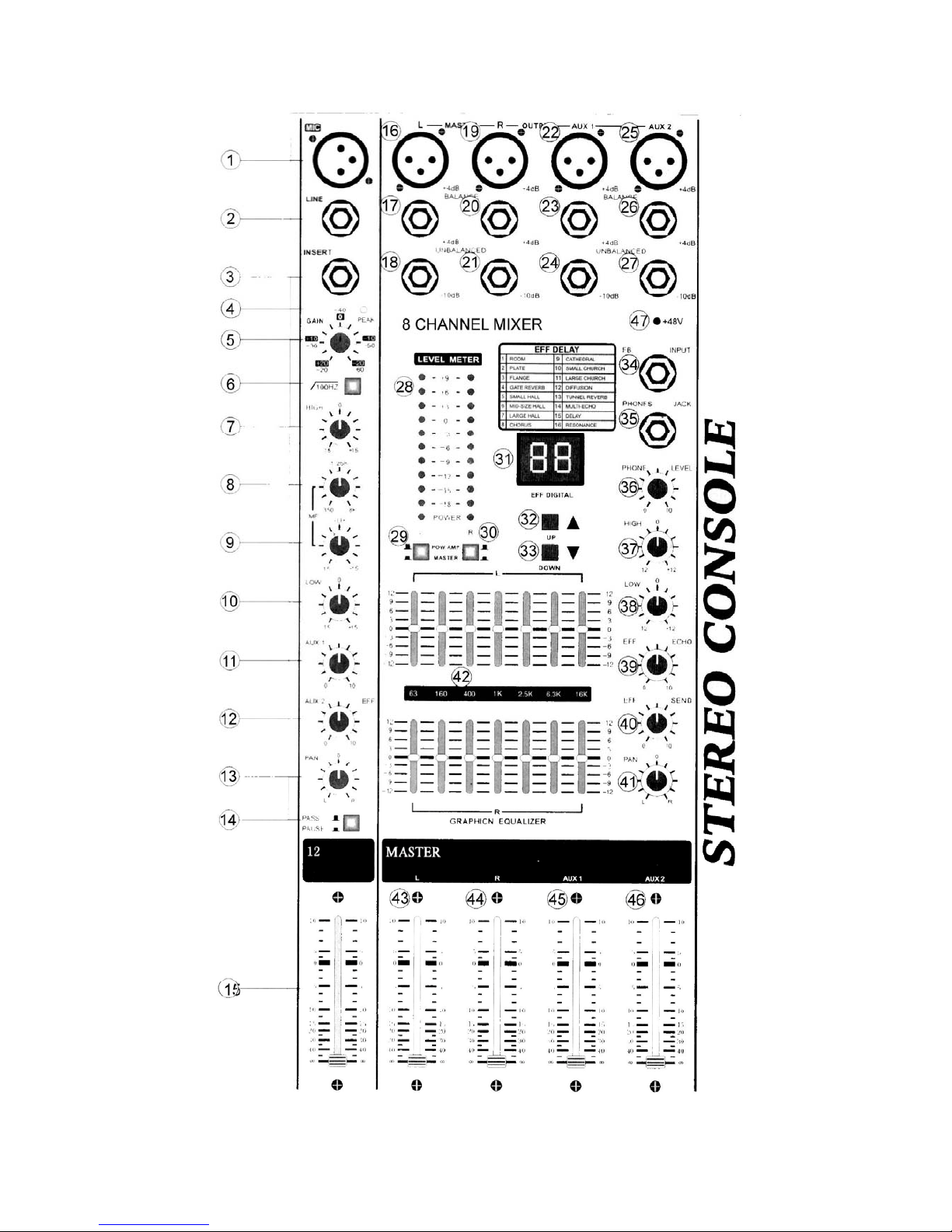
FIG. 1
1. XLR mic input suitable for balanced and unbalanced signals.
2. 6.3 mm Line input suitable for balanced and unbalanced signals.
3. 6.3 mm Line insert Jack, + TIP input, - RING output.
4. Overload detection LED of the input signal on each channel.
5. Gain control on each channel with 40 dB control range.
6. Switchable high-pass filter removing the frequencies below 100 Hz.
7. High frequency level control providing ± 15 dB cut or boost on a frequency of 10 kHz.
8. Mid frequency tune control, tuning the frequencies from 350 Hz - 8 kHz.
9. Mid frequency level control providing ± 15 dB cut or boost on a frequency of 350 Hz - 8 kHz.
10. Low frequency level control providing ± 15 dB cut or boost on a frequency of 100 Hz.
11. AUX 1 level control for each channel. Sets the level of the AUX1 bus for every Line.
12. AUX 2 level control for each channel. Sets the level of the AUX1 bus and the effect level for every
Line.
13. Volume control for every Line. Sets the volume between left and right of the master output
channel.
14. Pause button: Press this button to pause, press again to resume play
15. Volume level control: Sets the signal strength for the left and right channel.
16. Left Line balanced XLR output, +4 dB.
17. Left Line unbalanced 6.3 mm output Jack, +4 dB.
18. Left Line unbalanced 6.3 mm output Jack, -10 dB.
19. Right Line balanced XLR output, +4 dB.
20. Right Line unbalanced 6.3 mm output Jack, +4 dB.
21. Right Line unbalanced 6.3 mm output Jack, -10 dB.
22. AUX 1 Line balanced XLR output, +4 dB.
23. AUX 1 Line unbalanced 6.3 mm output Jack, +4 dB.
24. AUX 1 Line unbalanced 6.3 mm output Jack, -10 dB.
25. AUX 2 Line balanced XLR output, +4 dB.
26. AUX 2 Line unbalanced 6.3 mm output Jack, +4 dB.
27. AUX 2 Line unbalanced 6.3 mm output Jack, -10 dB.
28. VU meter: displays the output level of the left and right main bus.
29. VU meter switch: Switches between the left channel power amplifier and the left main bus output
signal.
30. VU meter switch: Switches between the right channel power amplifier and the right main bus
output signal.
31. Effect time, digital indicator, 1-16 bands
32. Effect time, digital indicator, increases an effect
33. Effect time, digital indicator, decreases an effect
34. Effect feedback 6.3 mm input Jack.
35. Stereo headphones 6.3 mm output Jack.
36. Stereo headphones level control.
37. Effect level control for the high frequencies, ± 12 dB cut or boost on a frequency of 3.5 kHz.
38. Effect level control for the low frequencies, ± 12 dB cut or boost on a frequency of 100 Hz.
39. Effect control: Sets the delay of the effects.
40. Effect volume control: Sets the volume between left and right of the master output channel.
41. Effect volume level control: Sets the signal strength of the master output for the left and right
channel.
42. Dual 7-band graphic equalizer: Individual control of the right and left channel.
63 Hz 160 Hz 400 Hz 1 kHz 2.5 kHz 6,3 kHz 16 kHz (@ ± 12 dB)
43. Left channel level control: Sets the left AMP input level and the master output level.
44. Right channel level control: Sets the right AMP input level and the master output level.
45. AUX 1 level control: Sets the signal level strength of AUX 1 channel.
46. AUX 2 level control: Sets the signal level strength of AUX 2 channel.
47. +48V Phantom power LED indicator

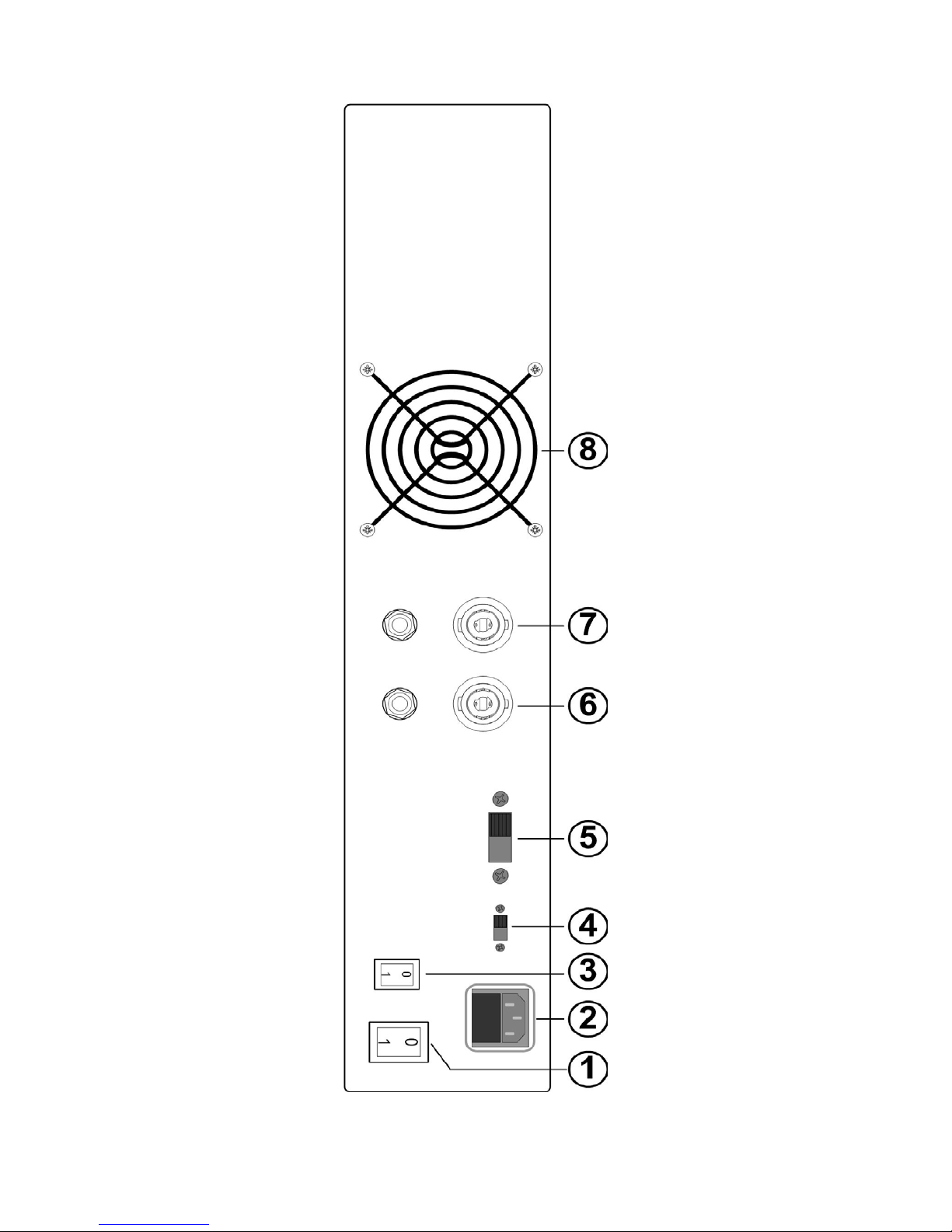
FIG. 2
1. Power switch (on/off).
2. Mains socket to be connected to a mains outlet & Fuse compartment.
3. Phantom power on/off switch.
4. Ground lift on/off
5. Input power selector 115Vac or 230Vac (optional)
6. Right Channel amplifier output 4-8 Ohms (speakon / 6,35mm jack)
7. Left Channel amplifier output 4-8 Ohms (speakon / 6,35mm jack)
8. Cooling fan: If the internal temperature exceeds 50°C, the fan will start to operate.
SPECIFICATIONS
Output power: ...........................................................................2x 350 W @ 4 Ohms
Output power: ...........................................................................2x 250 W @ 8 Ohms
Frequency range: ..................................................................20 - 20.000 Hz (±2 dB)
Mic input: .......................................................................................................-60 dBu
Line input: ......................................................................................................-10 dBu
Line Insert input: ............................................................................................ -10 dBu
Effect Return input: ........................................................................................ -10 dBu
Master output: ...............................................................................+4 dB @ 150 Ohm
Aux output: ....................................................................................+4 dB @ 150 Ohm
Effect Send Output: ...................................................................-10 dBu @ 10 kOhm
Equalizer High: .............................................................................. ±15 dB @ 10 kHz
Equalizer Mid: ..................................................................... ±15 dB @ 350 - 8000 Hz
Equalizer Low: ...............................................................................±15 dB @ 100 Hz
Equalizer output: ................................±12 dB @ 63, 160, 400, 1k, 2.5k, 6.3k, 16kHz
Distortion (THD): ............................................................................................ < 0.1 %
Power supply: ..................................................................................230 VAC / 50 Hz
Dimensions 8ch (wxhxd): ..........................................................530 x 180 x 475 mm
Dimensions 12ch (wxhxd): ........................................................665 x 180 x 475 mm
Weight 8ch: ..................................................................................................... 17.5 kg
Weight 12ch: ................................................................................................... 21.5 kg
• Specifications and design subject to changes without prior notice.
Do not attempt to make any repairs yourself. This would invalid your warranty.
Do not make any changes to the unit. This would also invalid your warranty.
The warranty is not applicable in case of accidents or damages caused by inappropriate use or disrespect of the warnings
contained in this manual.
SkyTronic UK cannot be held responsible for personal injuries caused by a disrespect of the safety recommendations and
warnings. This is also applicable to all damages in whatever form.
 Loading...