

Skytec 172.564, 172.567 Instruction Manual
12 CHANNEL MUSIC MIXER
172.564
20 CHANNEL MUSIC MIXER
172.567
Instruction Manual
Gebruiksaanwijzing
Mode d’Emploi
Gebrauchsanleitung

GB
Congratulations on the purchase of this SkyTec mixer.
Please read this manual carefully prior to using the unit.
Warning:
- Read the manual prior to using the unit.
- Keep the manual for future reference.
- Keep the packaging for safer transport in its original packaging
- For indoor use only.
- Prior to the first use, have the unit checked by a qualified person.
- The unit contains voltage carrying parts. DO NOT open the mixer.
- When you unplug the unit from the mains always pull the plug, never the lead.
- Never plug or unplug the unit with wet hands.
- If the plug and/or mains lead are damaged, they need to be repaired by a qualified technician.
- If the unit is damaged to an extent that you can see internal parts, do not plug the unit into a
mains outlet.
- Repairs and lamp replacement has to be carried out by a qualified technician.
- Only connect this unit to an earthed mains outlet of 230Vac/50Hz and 10-16A.
- Do no place the unit near heat sources.
- Always unplug the unit during a thunderstorm or when it is not in use.
- If the unit has not been used for a longer period of time, condensation can occur inside the
housing. Please let the unit reach room temperature prior to use.
- Keep out of the reach of children.
- All channel controls and the master volume control must be set to zero prior to switching the
unit on.
- Set the channel slider controls slowly. Fast variation can overload the speakers.
- To prevent clipping of the amplifier do not set the volume level too high.
- Switch the amplifier on at latest and switch it off at first.
- Do not use cleaning sprays for the slider controls. The residues of these spray cause dust
deposits in the controls. If a problem occurs, please consult a specialist.
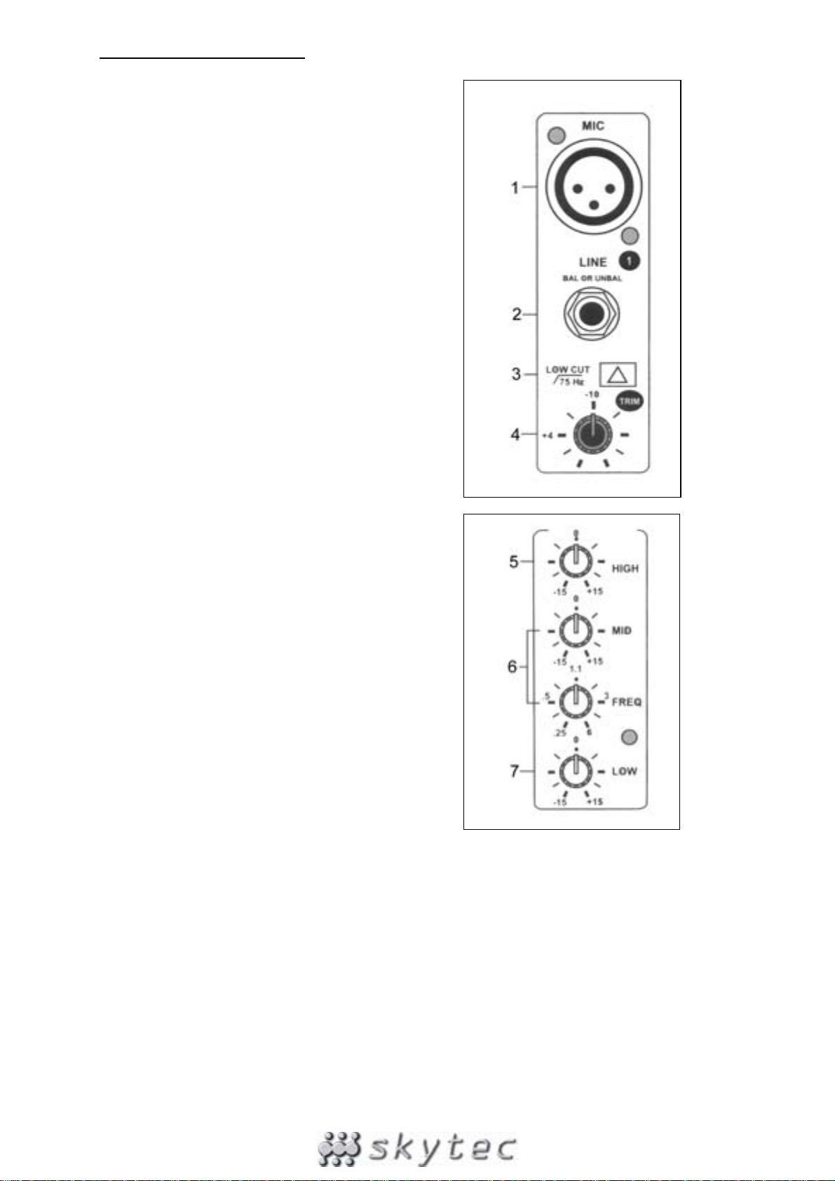
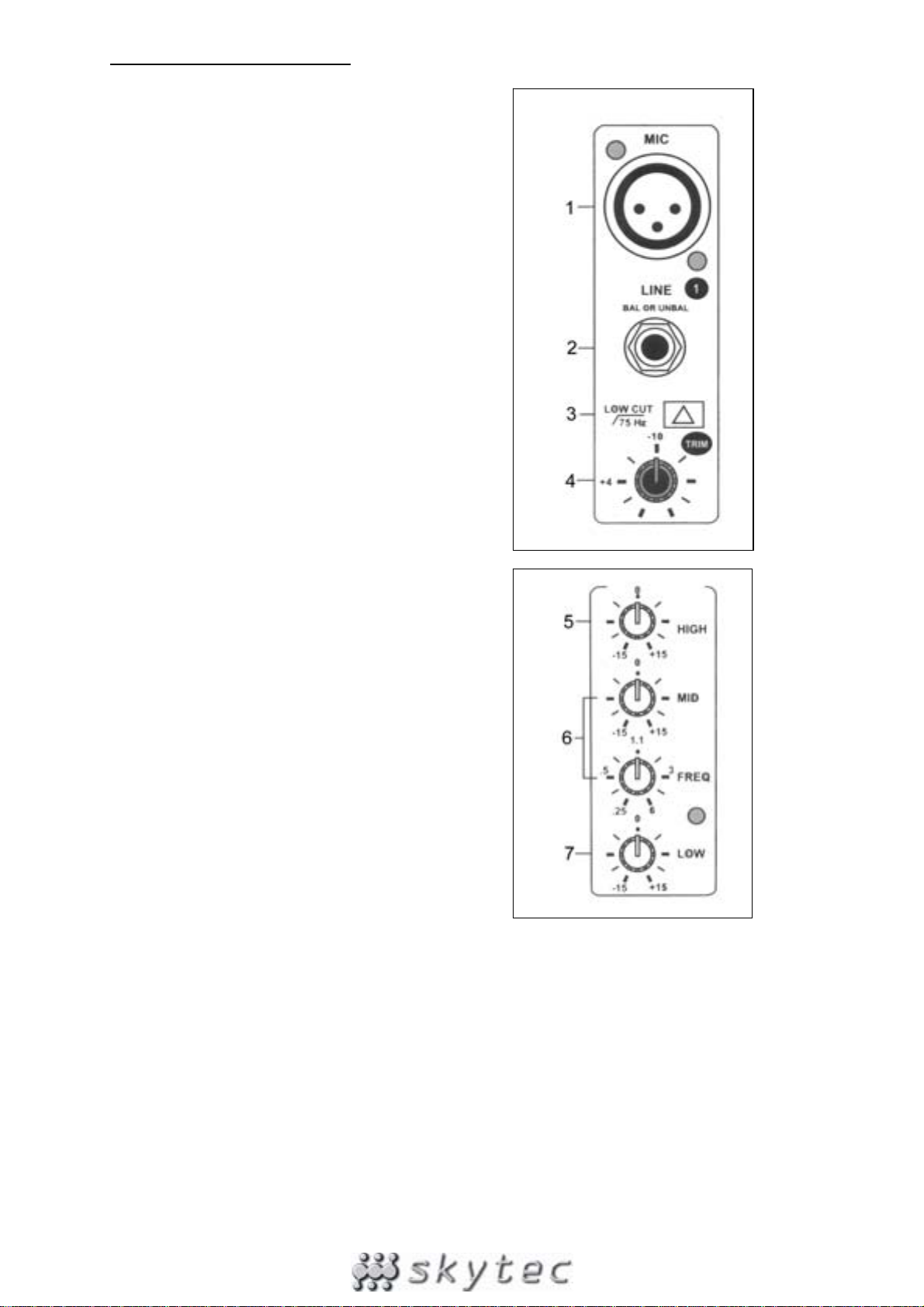
MONO INPUT CHANNELS
1. BALANCED INPUT
Electronically balanced input for standard XLR
connectors. Features a 48V phantom power (to be
switched on via (35))
2. LINE INPUT
This unbalanced input accepts balanced and
unbalanced microphones, turntables, keyboard, etc.
3. LOW CUT
This push button improves the use of the
microphone. When the low cut function is activated
you have fewer problems with noise, interference
and pop noises.
4. TRIM
This function allows you to set the input sensitivity
of each channel to the constant level of the input
signal.
5. HIGH
Sets the high frequencies on each channel. Leave
this knob in the “0” position first. Set the signal once
the music has started to play in order not to damage
the speakers. Turn cw to increase the higher
frequencies and ccw to reduce them.
6. FREQUENCY & MID
This equalization function has a “bell” reaction with
a fixed Q fader of 1.5. The frequency can be set
between 100 & 8000 Hz and the volume between
-15 & +15 dB.
7. LOW
This knob sets the low frequency range of each
channel. Leave this knob in the “0” position first. Set
the signal once the music has started to play in
order not to damage the speakers. Turn cw to
increase the lower frequencies and ccw to reduce
them
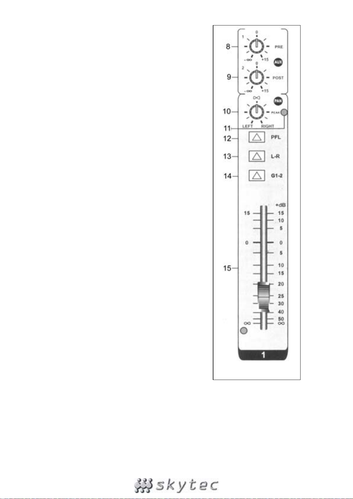
8. AUX 1
This AUX send control is pre-fade, post-EQ. Therefore the
signal is not controlled by the position of the fader and the
routing status of the channel. This send function is very
convenient to cross monitor signals that have to be
controlled separately from the PA installation.
9. AUX 2
This AUX send control is post-fade, post-EQ. Therefore
the signal is sensitive to changes in the fader position. It is
normally used to feed an audio signal to an effect unit. As
the signals are always sent back into the mixer, the fader
must be able to control these signals.
10. PAN
The PAN control feeds continuously variable quantities of
the post-fader signal to the left or right and G1 or G2 main
busses. In the centre position / ”∞” the same signal is sent
to the left and right and the G1 and G2 main busses.
11. PEAK
A red LED lights up when the peak signal reaches the
maximum value that the mixer can handle. If this lasts
over a longer period of time, you might damage the unit.
The LED lights up at a volume level of 5 dB below
clipping.
12. PFL
If this button is pressed, you can monitor the signal via
headphones. This applies only to channels where the PFL
function is switched on. All other channel can then not be
monitored through the headphones
13. STEREO
When this button is pressed, you can use the L-R master
faders to allocate a stereo position to the signal of this
channel over the output signal.
14. GRPS 1-2
When this button is pressed, you can use the G1-2 master
fader. Now, the signal is bundled with all other channels
on which this function is activated. The L-R master faders
are inactive now.
15. CHANNEL FADER
This slider control sets the volume of that channel. Set it to
the “0” position when you connect a signal. Push the slider
control upwards until the required output volume is
reached. Please note, you can further change the volume
of this channel via one of the master faders.
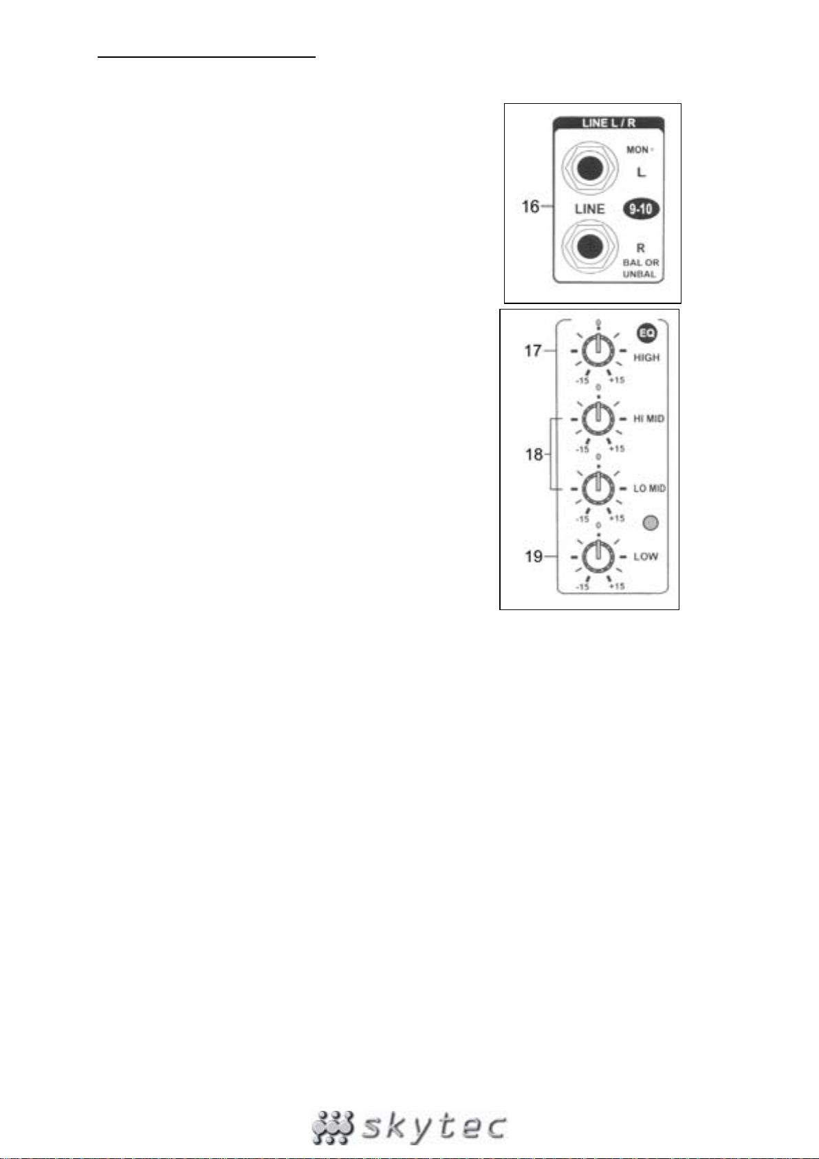
STEREO INPUT CHANNELS
16. LEFT (MONO) / RIGHT
6.3 mm jack input for connection of a Line signal. If L+R are
both connected, this channel is stereo. If only the left input
is connected, a mono signal is fed to the left and the right
bus (the signal is simply spread over the left and the right
bus). If you connect only the right input, the signal is fed
only to the right bus.
17. HIGH
This knob controls the high frequencies per channel. Set
this button always in the “0” position first. Control the signal
once the music has started playing in order to prevent
damage to the speakers. Turn cw to increase the high
frequencies and ccw to reduce them.
18. HI MID & LO MID
This knob controls the medium range frequencies per
channel. Set this button always in the “0” position first.
Control the signal once the music has started playing in
order to prevent damage to the speakers. Turn cw to
increase the medium frequencies and ccw to reduce them.
19. LOW
This knob controls the low frequencies per channel. Set
this button always in the “0” position first. Control the signal
once the music has started playing in order to prevent
damage to the speakers. Turn cw to increase the low
frequencies and ccw to reduce them.
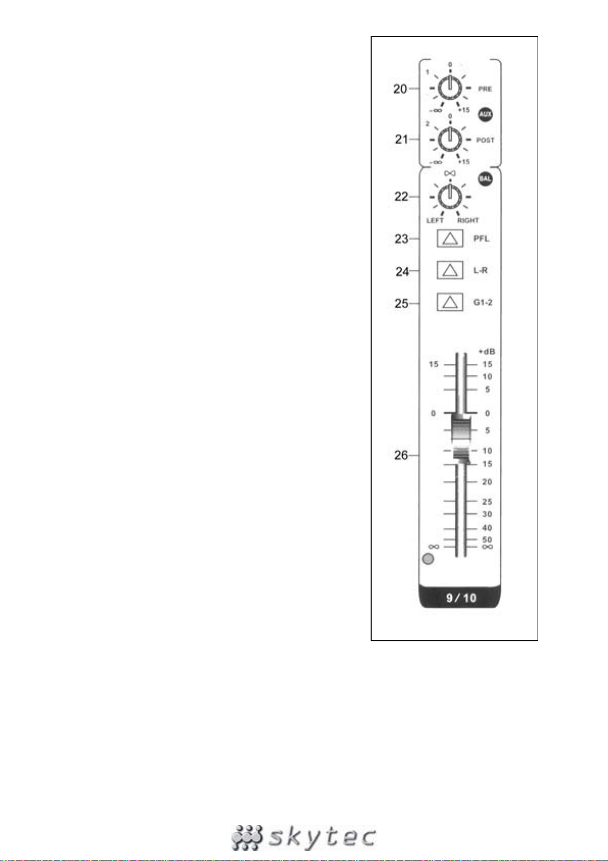
20. AUX 1
This AUX send control is pre-fade, post-EQ. Therefore the
signal is not influenced by the position of the fader and the
routing status of the channel. This send function is very
convenient to cross monitor signals that have to be
controlled separately from the PA installation.
21. AUX 2
This AUX send control is post-fade, post-EQ. Therefore the
signal is sensitive to changes in the fader position. It is
normally used to feed an audio signal to an effect unit. As
the signals are always send back into the mixer, the fader
must be able to control these signals.
22. BAL
The BAL control feeds continuously variable quantities of
the post-fader signal to the left or right and G1 or G2 main
busses. In the centre position ”∞” the same signal is sent to
the left and right and the G1 and G2 main busses.
23. PFL
If this button is pressed, you can monitor the signal via
headphones. This applies only to channels where the PFL
function is switched on. All other channel can then not be
listened to through the headphones
24. STEREO
When this button is pressed, you can use the L-R master
faders to allocate a stereo position to the signal of this
channel over the output signal. The L-R master faders are
inactive in that case.
25. GRPS 1-2
When this button is pressed, you can use the G1-2 master
fader. Now, the signal is bundled with all other channels on
which this function is activated. The L-R master faders are
inactive now.
26. CHANNEL FADER
This slider control sets the volume of that channel. Set it to
the “0” position when you connect a signal. Push the slider
control upwards until the required output volume is reached.
Please note: you can further change the volume of this
channel via one of the master faders.
MASTER SECTION
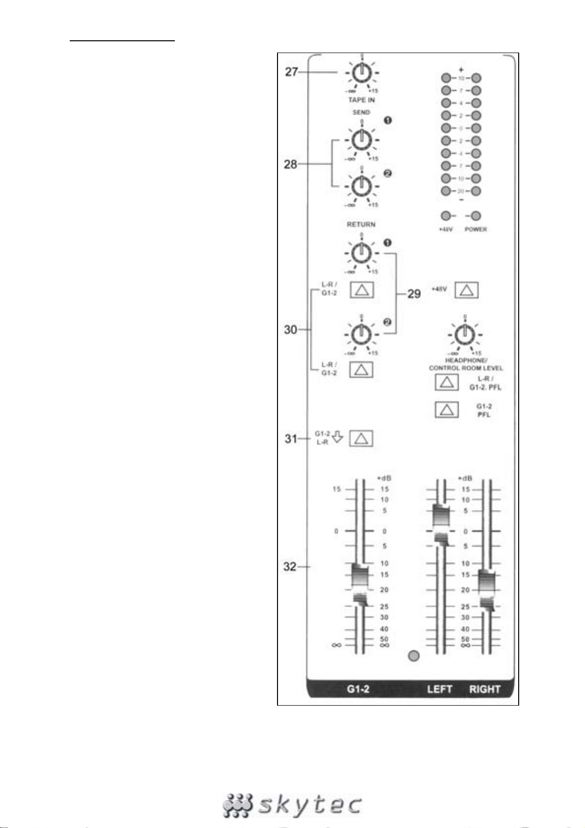
27. TAPE LEVEL
This knob changes the volume level of
the TAPE IN if this input is connected.
Turn cw to increase the level and ccw to
reduce it
28. AUX 1-2 SENDS
This knob changes the volume level of
the AUX Send if this output is connected.
Turn cw to increase the level and ccw to
reduce it
29. AUX RETURN 1-2
This knob changes the volume level of
the AUX Return input signal. Turn cw to
increase the level and ccw to reduce it
30. ST/G1-2
If this switch is not pressed, the return
signal will be sent to the stereo output. If
the switch is pressed in, the return signal
will be sent to the G1-2 output.
31. ST/G1-2
If this switch is pressed, the G1-2 mix
output signal is sent to the stereo bus.
Thus the G1-2 busses can mix two mono
subgroups into a single output signal
when no stereo sound is required.
32. GRPS 1-2 OUTPUT FADER
This slider control sets the volume level
of the G1-2 bus.
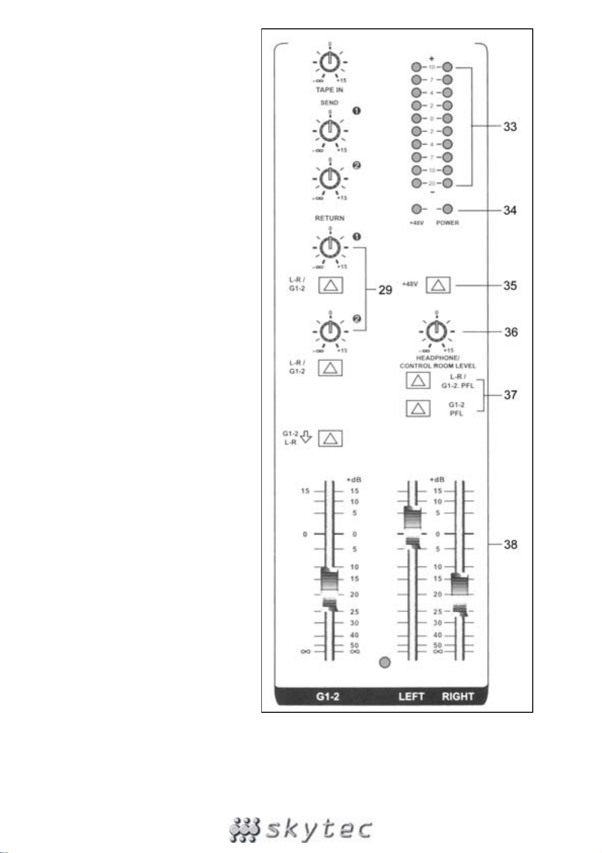
33. OUTPUT LEVEL INDICATOR (VU
METER)
This VU-meter displays the output
levels of the lift and right channels,
GPRS1-2, headphones and control
room so that you can monitor the
output condition of the signal.
34. ON/OFF & PHANTOM LEDs
The LEDs light up when their
functions are switched on.
35. PHANTOM POWER SWITCH
If you press this button all balanced
microphone inputs are powered by
48V which allows the use of
condenser microphones.
36. HEADPHONE / CONTROL ROOM
LEVEL
This single volume control sets the
volume level of the headphones
and of the monitors. Turn cw to
increase the volume and ccw to
lower it.
37. HEADPHONE SWITCH
If the L-R / G1-2 PFL button is not
pressed in, the output signal is sent
in stereo to the monitors. If the
buttons are pressed in, the signal is
sent via the headphones. The G1-2
fader allows you to determine the
volume level of the headphones.
38. MASTER FADER OUTPUT LEVEL
(LEFT/RIGHT)
It’s the master fader control of the
volume level of a stereo signal. Left
and right are controlled separately.
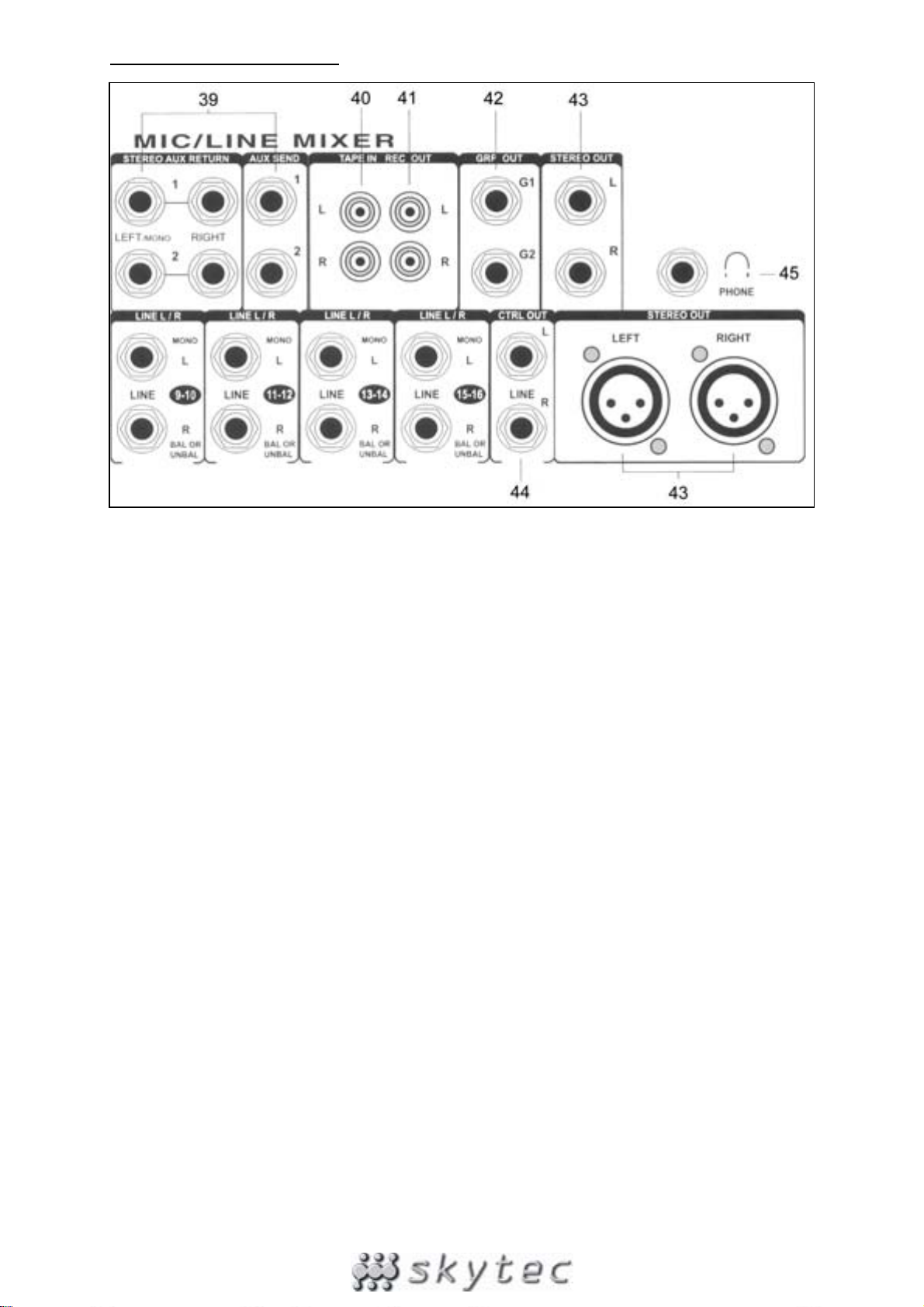
MIXER OUTPUT SECTION
39. STEREO AUX RETURNS & SENDS
To be connected to all kinds of effect units
40. TAPE INPUT JACK
Connect this jack to a cassette deck for playback
41. RECORD PIN JACK
This jack has to be connected to a cassette deck for recording of the output signal.
42. GRPS 1-2 OUTPUT JACK
Connect this jack to an amplifier to reproduce the G1-2 signal.
43. STEREO OUTPUT JACK (LEFT/RIGHT)
This allows you to connect the output signal to an amplifier via 6.3mm jacks or XLR connectors
44. CONTROL ROOM OUTPUT JACK
For connection to a monitor (active speaker or amplifier)
45. HEADPHONE JACK
To be connected to headphones in order to monitor on each channel the PFL or the L/R and the
G1-2.
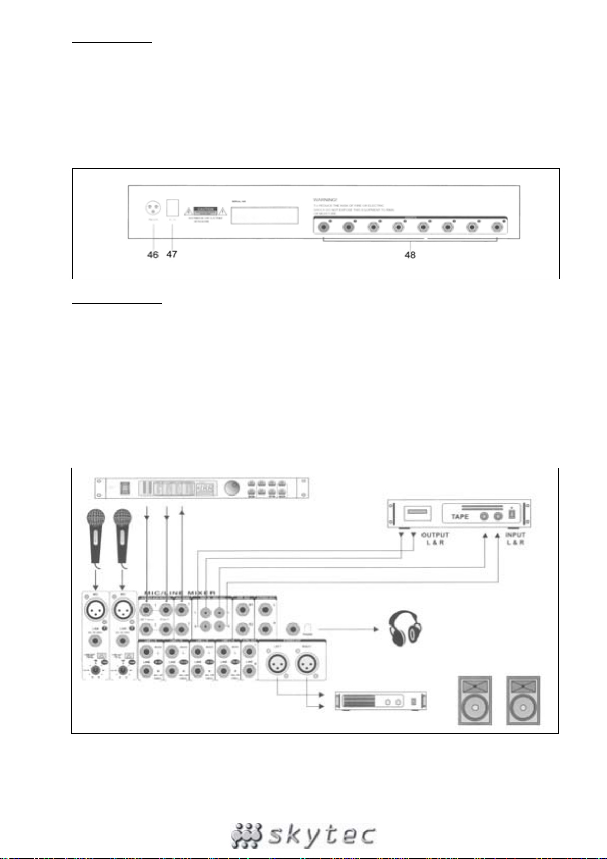
REAR PANEL
46. POWER JACK
Mains power inlet.
47. MAINS SWITCH
Press this button to switch the mixer ON or OFF. The LED (29) lights up when this switch is in ON
position.
48. INSERT
To feed the input signals into effect units, electrical instruments, etc.`
INSTALLATION
Do not mix up the cable in order to avoid wrong connections. Connect the leads one by one and not all
leads on one side first and then all on the other side. In the worst case, you might permanently
damage the unit. Figure 2 shows an example of possible connections.
Prior to connecting the mixer, set all controls to “0”. You can connect microphone or line units to the
mono channels, all kinds of line units to the stereo channels and effect units to the AUX Return. You
can also connect Midi instruments to the AUX Return.
If you connect a microphone, make sure that the phantom power is switched OFF. DO NOT use
unbalanced units when the phantom power is switched on. Do not short-circuit the 48V ci rcuit of the
phantom power to the ground. You might heavily damage the unit.
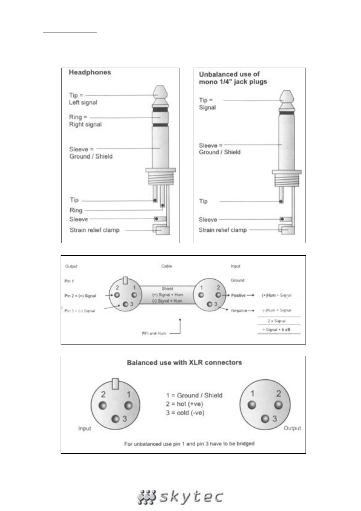
CONNECTIONS
On a balanced in/output, always use balanced equipment. You can use either balanced or unbalanced
equipment on an unbalanced in/output. See the drawings below for the equipment that you can use:
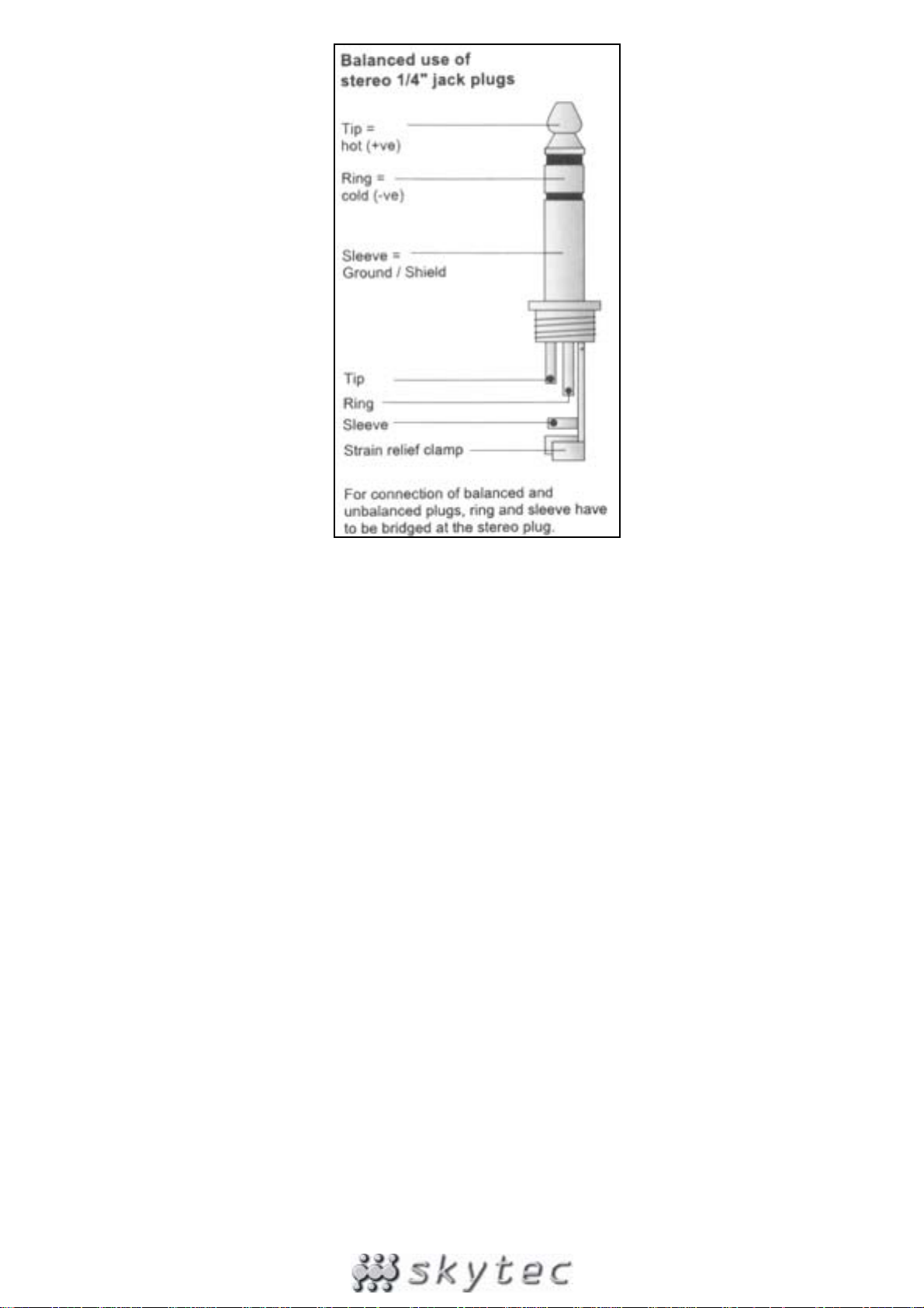
If possible, connect the balanced outputs to other balanced units to avoid interference.

SPECIFICATIONS
Mono inputs
Mic input: ..................................electronically balanced, discrete input configuration
Frequency response: ...........................................................10 Hz – 20 kHz (± 3 dB)
Distortion: ..................................................................... <0,01% @ +4 dBu (± 1 kHz)
Input impedance: ................................................................... 150 Ohm @ -129.5 dB
TRIM range: ..................................................................................... +10 dB - +60 dB
Line input: .............................................................................. electronically balanced
Frequency response: ...........................................................10 Hz – 20 kHz (± 3 dB)
Distortion: ..................................................................... <0,01% @ +4 dBu (± 1 kHz)
Line level range: ........................................................................... +10 dBu - -40 dBu
Equalizer: ....................................................................................................................
High: .............................................................................................. 12 kHz (± -15 dB)
Mid: ....................................................................................100 Hz - 8 kHz (± -15 dB)
Low: ................................................................................................. 80 Hz (± -15 dB)
Stereo inputs
Line input: ................................................................................................unbalanced
Frequency response: ...........................................................10 Hz – 20 kHz (± 3 dB)
Distortion: ..................................................................... <0,01% @ +4 dBu (± 1 kHz)
Equalizer: ....................................................................................................................
High: .............................................................................................. 12 kHz (± -15 dB)
Mid bell: ............................................................................100 Hz – 8 kHz (± -15 dB)
Low: ................................................................................................. 80 Hz (± -15 dB)
Low cut (high pass) filter: .................................................................... 75 Hz @ -3 dB
Master section
Max output level: ........................................................................ + 22 dBu, balanced
AUX send max output level: ..................................................... +22 dBu unbalanced
Control room output level: ........................................................ +22 dBu unbalanced
Signal/Noise ratio: ........................................................................................ >112 dB
Power supply: ....................................................................................230 Vac, 50 Hz
•
Specifications and design subject to changes without prior notice.
Do not attempt to make any repairs yourself. This would invalid your warranty.
Do not make any changes to the unit. This would also invalid your warranty.
The warranty is not applicable in case of accidents or damages caused by inappropriate use or disrespect of the warnings
contained in this manual.
SkyTronic UK cannot be held responsible for personal injuries caused by a disrespect of the safety recommendations and
warnings. This is also applicable to all damages in whatever form.

NL
Hartelijk dank voor de aanschaf van ons SkyTec mengpaneel. Lees deze gebruiksaanwijzing
aandachtig door alvorens het apparaat in bedrijf te stellen.
WAARSCHUWING:
- Lees altijd eerst de gebruiksaanwijzing voordat u een apparaat gaat gebruiken.
- Bewaar de handleiding zodat elke gebruiker hem eerst kan doorlezen.
- Bewaar de verpakking zodat u indien het apparaat defect is, dit in de originele verpakking kunt
opsturen om beschadigingen te voorkomen.
- Alleen voor gebruik binnenshuis.
- Voordat het apparaat in werking wordt gesteld, altijd eerst een deskundige raadplegen.
- In het apparaat bevinden zich onder spanning staande onderdelen; open daarom NOOIT dit
apparaat.
- Bij het verwijderen van de stekker uit het stopcontact nooit aan het netsnoer trekken.
- Verwijder of plaats een stekker nooit met natte handen resp. uit en in het stopcontact.
- Indien de stekker en/of netsnoer als snoeringang in het apparaat beschadigd zijn dient dit door
een vakman hersteld te worden.
- Indien het apparaat zo beschadigd is dat inwendige (onder)delen zichtbaar zijn mag de stekker
NOOIT in het stopcontact worden geplaatst én het apparaat NOOIT worden ingeschakeld. Neem
in dit geval contact op met SkyTronic BV.
- Reparatie aan het apparaat dient te geschieden door resp. een vakman of een deskundige.
- Sluit het apparaat alléén aan op een 230VAC / 50Hz geaard stopcontact, verbonden met een 10-
16A meterkastgroep.
- Toestel niet opstellen in de buurt van warmte bronnen zoals verwarming etc.
- Bij onweer altijd de stekker uit het stopcontact halen, zo ook wanneer het apparaat voor een
langere tijd niet gebruikt wordt.
- Als u het apparaat lang niet gebruikt heeft en het weer wil gebruiken kan er condensatiewater
ontstaan; laat het apparaat eerst op kamertemperatuur komen alvorens het weer in werking te
stellen.
- Om ongevallen in bedrijven te voorkomen moét rekening worden gehouden met de daarvoor
geldende richtlijnen en moeten de aanwijzingen/waarschuwingen worden gevolgd.
- Het apparaat buiten bereik van kinderen houden.
- Zorg er altijd voor dat wanneer het apparaat wordt ingeschakeld dat alle kanaalschuiven en het
mastervolume op minimaal staan.
- Regel de kanaalschuiven met beleid, snelle variatie kan voor overbelasting zorgen met
beschadiging van uw luidsprekers als gevolg.
- Zorg ervoor dat de versterker nooit gaat clippen: Dit gebeurt wanneer de clip leds, meestal op het
front van de versterker, opgaan lichten. Regel het volume dusdanig dat dit niet gebeurt.
- Schakel een versterker altijd als laatste aan en schakelt hem als eerste uit.
- Gebruik geen schoonmaakspray om de schuifregelaars te reinigen. Restanten van deze spray
zorgen ervoor dat smeer en stof ophopen in de regelaars. Raadpleeg bij storing te allen tijde een
deskundige.
MONO INGANGSKANALEN
1. BALANCE INGANG
Elektronisch gebalanceerde ingangen voor
standaard XLR connectoren. Met 48V fantoom
voeding (deze schakelt u in met (35)).
2. LINE INGANG
Deze ongebalanceerde ingang accepteert zowel
gebalanceerde als ongebalanceerde microfoons,
draaitafels, keyboards etc.
3. LOW CUT
Deze drukknop is bedoeld ter ondersteuning voor
microfoongebruik. Als de low cut ingeschakeld is,
heeft u minder last van ruis, storing en “popping”.
4. TRIM
Met deze functie kunt u de ingangsgevoeligheid van
elk kanaal aanpassen aan het constante niveau van
het ingangssignaal.
5. HIGH
Voor het instellen van de hoge tonen voor elk
kanaal. Zet deze knop altijd op de “0” positie. Pas
het signaal aan als de muziek eenmaal afspeelt. Dit
raden wij u aan omdat u anders uw luidsprekers
kunt beschadigen. Met de klok meedraaien zorgt
voor meer hoge tonen, tegen de klok in draaien
voor minder.
6. FREQUENCY & MID
Deze equalisatie functie heeft een ”bell” reactie. Met
een vaste Q fader van 1,5. De frequentie is
instelbaar tussen 100 & 8000 Hz en de
geluidssterkte is instelbaar tussen -15 & +15 dB.
7. LOW
Stel hier het lage frequentiebereik van elk kanaal in.
Zet deze knop altijd op de ”0” positie. Pas het
signaal aan als de muziek enmaal afspeelt. Dit
raden wij u aan omdat u anders uw luidsprekers
kunt beschadigen. Met de klok meedraaien zorgt
voor meer lage tonen, tegen de klok in draaien voor
minder.
 Loading...