

Page 1

Southwest Windpower, Inc.
1801 West Route 66
Flagstaff, Arizona 86001
Phone: 928.779.9463
Fax: 928.779.1485
Web: www.skystreamenergy.com
Skystream 3.7
Owner’s Manual
INSTALLATION
OPERATION
MAINTENANCE
T
M
August 2006 Southwest Windpower, Inc. All Rights Reserved
Page 2
SOUTHWEST WINDPOWER SKYSTREAM 3.7 OWNER’S MANUAL
1
Southwest Windpower
Congratulations on your purchase and welcome to our family!
Dear Skystream 3.7™ Owner,
Thank you for your purchase of Skystream.You have just selected the most technologically advanced, cost-effective renewable energy
appliance available for a home or small business. We congratulate you on your choice and are confident you will experience years of
dependable service.
Before going any further, please complete and return the enclosed Warranty Registration Card. The conditions of your warranty
are dependent upon the proper installation of Skystream. Furthermore, this will assure you of being kept up-to-date with the latest
developments from Southwest Windpower.These include new options, performance tips, updated software to maximize output and
user notices. It is impor tant to know that we do not sell or distribute your information to any third party. We understand your privacy
is important.
If you have any questions or comments, we would like to hear from you. Please call during working hours (Monday-Friday – 8:00am to
5:00pm Mountain Standard Time). Our number is 928-779-9463, toll-free 866-807-9463.
Again, welcome to our family and thank you for investing in the future of wind energy with Skystream.
Best Regards,
Southwest Windpower
Enter the serial and model number below
Serial Number __________________________________
Model Number __________________________________
Skystream Installation Manual
Document No. 0313
Page 3
SOUTHWEST WINDPOWER SKYSTREAM 3.7 OWNER’S MANUAL
2
IMPORTANT SAFETY INSTRUCTIONS
READ THESE INSTRUCTIONS IN THEIR ENTIRETY BEFORE INSTALLING OR OPERATING.
1) SAVE THESE INSTRUCTIONS. This manual contains important instructions for
Skystream that must be followed during installation and maintenance.
2) Read, understand and respect all warnings.
3) Do not install Skystream around standing water.
4) Do not install Skystream on a windy day.
5) Install Skystream in accordance with National Electric Code (NEC) and local
building codes.
6) Always obtain a building permit before construction.
7) When moving Skystream or any heavy objects to the site, use a car t to prevent
back injury.
8) If unusual noise or abnormal operation is observed from Skystream, turn off the
machine and contact authorized service per sonnel.
9) This wind generator complies with international safety standards and therefore the
design or its installation must never be compromised.
a. Do not open the inver ter cover, doing so without factory authorization
will void the warranty.
b. Apply the proper torque to all fasteners.
c. Torque field wire connections to Skystream to 20-25 inch-lbs. (2.3-2.5 N-m).
Refer to Electrical Connections section of this manual (Section 2-1-2).
d. Install only on a Professional Engineer (PE) cer tified tower.
e. Do not paint the blades.
10) Use only proper grounding techniques as established by the NEC.
11) Properly complete the warranty registration card; failure to complete and return
the card ma
y affect your warranty.
12) Skystream must be installed in accordance with this manual and local and national
building codes. Failure to comply with the manual and local codes will affect and
possibly void your warranty.
13) Skystream uses high v
oltage and is potentiall
y dangerous.
Be sure to use all safety
precautions at all times.
Professional installation
highly recommended
TIP: Helpful information
to ease the installation
Warning: Risk of injury or
death - proceed with extreme
caution
Professional installation
highly recommended
In this manual
Page 4

SOUTHWEST WINDPOWER SKYSTREAM 3.7 OWNER’S MANUAL
3
Table of Contents
Important Safety Instructions _______________________________ 2
Skystream 3.7 Specifications ________________________________ 4
1) BEFORE INSTALLATION __________________________ 5
1-1
Package Contents______________________________ 5-6
1-2
Recommended Tools __________________________ 6
1-3
Skystream Options ____________________________ 7
1-4
Skystream Project Preparation ____________________ 8
1-4-1
Finding the Best Location for Your Skystream ____ 8
1-4-2
Tower Types ____________________________ 9
1-4-3
Working With Your Utility __________________ 9
1-4-4
Working With Your Local Zoning Authority ______ 9
2) INSTALLATION____________________________________ 10
2-1
Electrical ____________________________________ 10
2-1-1
Wiring ________________________________ 10
2-1-2
Electrical Connections ______________________ 12
2-1-3
Wire Sizing ____________________________ 12
2-1-4
Grounding ____________________________ 13
2-1-5
Fusing/Circuit Breaker ______________________ 13
2-1-6
Checking Grid Connectivity __________________ 13
2-2
Installing Skystream on a Tower ____________________ 14-15
2-2-1
Mounting Skystream to the Tower ____________ 15
2-3
Testing on the Ground ________________________ 15
2-3-1
Electrical Test ____________________________ 15
2-4
Blade, Nosecone and Antenna Assembly ____________ 16-17
3) OPERATION AND MAINTENANCE________________ 18
3-1
Key Operating Characteristics ____________________ 18
3-2
Frequentl
y
Asked Questions
______________________ 19
4) APPENDICES
Appendix A
EElleeccttrriiccaall CCoonnnneeccttiioonn DDiiaaggrraamm OOppttiioonns
s
1 Junction Box at Tower Base______________________ 1
2
Direct Run to Home __________________________ 2
Appendix B
FFoouunnddaattiioonn IInnssttaallllaattiioonn MMaannuuaal
l
1 Introduction ________________________________ 2
2
Pier Foundation______________________________ 2
2
Mat Foundation______________________________ 7
2
Electrical Conduit ____________________________ 9
Appendix C
TToowweerr IInnssttaallllaattiioonn MMaannuuaal
l
1 Introduction ________________________________ 2
2
Set Up & Preparation ________________________ 3
3
Raising the
T
o
w
er
____________________________ 6
4
Lowering the Tower __________________________ 7
5
Leveling the Tower____________________________ 8
6
Gin P
ole Instr
uction Sheet
______________________ 9
Page 5
SOUTHWEST WINDPOWER SKYSTREAM 3.7 OWNER’S MANUAL
4
SOUTHWEST WINDPOWER SKYSTREAM 3.7 OWNER’S MANUAL
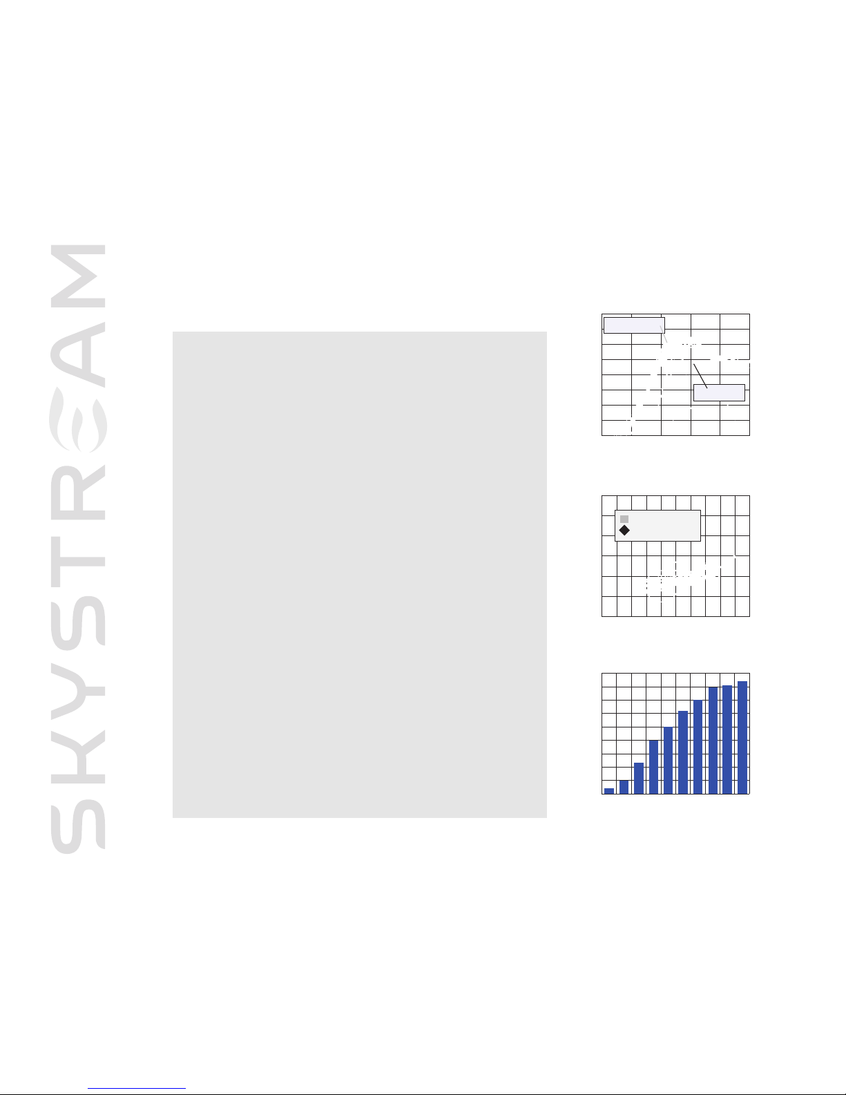
Skystream 3.7TMTechnical Specifications
9
0
80
7
0
60
50
40
30
mph 0 4.5 9 13.4 17.9 22.3 27 31.3 36 40.25 44.75
m/s 0 2 4 6 8 10 12 14 16 18 20
Background Sound
Generator Operating
2400
2100
1800
1
500
1200
900
600
300
0
m
ph 0 11 22.3 33.5 44.75 60
m/s 0 5 10 15 20 25
Southwest binned
2
0-sec average
N
WTC
1-min averages
SOUND REPORT
PERFORMANCE GRAPH
Sound Pressure Level dB (A)
Standardized Wind Speed
Watts
Standardized Wind Speed
Model Skystream 3.7
Rated Capacity 1.8 kW rated 2.4 kW peak
Weight 170 lbs. / 77 kg
Rotor Diameter 12 feet / 3.72 meters
Swept Area 115.7 ft2 / 10.87 m
2
Type Downwind rotor with stall regulation control
Direction of Rotation Clockwise looking upwind
Blade Material Fiberglass reinforced composite
Number of Blades 3
Rated Speed 50 - 325 rpm
Tip Speed 66 - 213 f/s / 9.7 - 63 m/s
Alternator Slotless permanent magnet brushless
Yaw Control Passive
Grid Feeding Southwest Windpower inverter 120/240 VAC 50-60/Hz
Braking System Electronic stall regulation w/redundant relay switch control
Cut-in Wind Speed 8 mph / 3.5 m/s
Rated Wind Speed 20 mph / 9 m/s
User Control Wireless 2 way interface remote system
Survival Wind Speed 140 mph / 63 m/s
Total Harmonic Distortion 2.7% at 2400W, meets UL1741 and IEEE1547.1
requirements.
900
800
700
600
500
400
300
200
100
0
mph 5.6 7.9 10 12.3 14.5 16.8 19 21.2 23.5 24.6
m/s 2.5 3.5 4.5 5.5 6.5 7.5 8.5 9.5 10.5 11
ENE RGY CHART
kWh per month (est)
Average Annual Wind Speed
Page 6
SOUTHWEST WINDPOWER SKYSTREAM 3.7 OWNER’S MANUAL
5
One - Before Installation
Instructions in this guide apply to Skystream Land and Skystream Marine U.S. models only. Please specify
“land” or “marine” when ordering parts or requesting service as components differ.
1-1 Package Contents
Before you begin, inspect the contents to make sure there is no damage or missing par ts.
l
Identify the parts of your Skystream system using the information on the next two pages.
l
Inspect for damage and/or missing parts.
Your Skystream wind generator is shipped in two boxes:
Box One: rotor blades (three each)
Box dimensions: 76”L x 15”W x 12”H (102 cm L x 56 cm W x 69 cm H)
Weight: 40 lbs (18 kg)
Upon opening, carefully inspect each of the blades to make sure there are no fractures or cracks in the surfaces. Although the Skystream
rotor blades are comprised of a durable compression molded fiberglass, damage can occur to the blades during shipping. Once inspected,
be sure to set them away from the construction site and protect them from any damage until they are ready for assembly.
Box Two: Skystream 3.7 wind generator assembly
Box dimensions: 40”L x 22”W x 27”H (102 cm L x 56 cm W x 69 cm H)
Weight: 175 lbs (80 kg)
Your Skystream comes in several versions in accordance with local utility requirements. Be sure to inspect the package and confirm you
have the right voltage and Hz. If you have ANY questions, call your dealer or the factory before continuing.
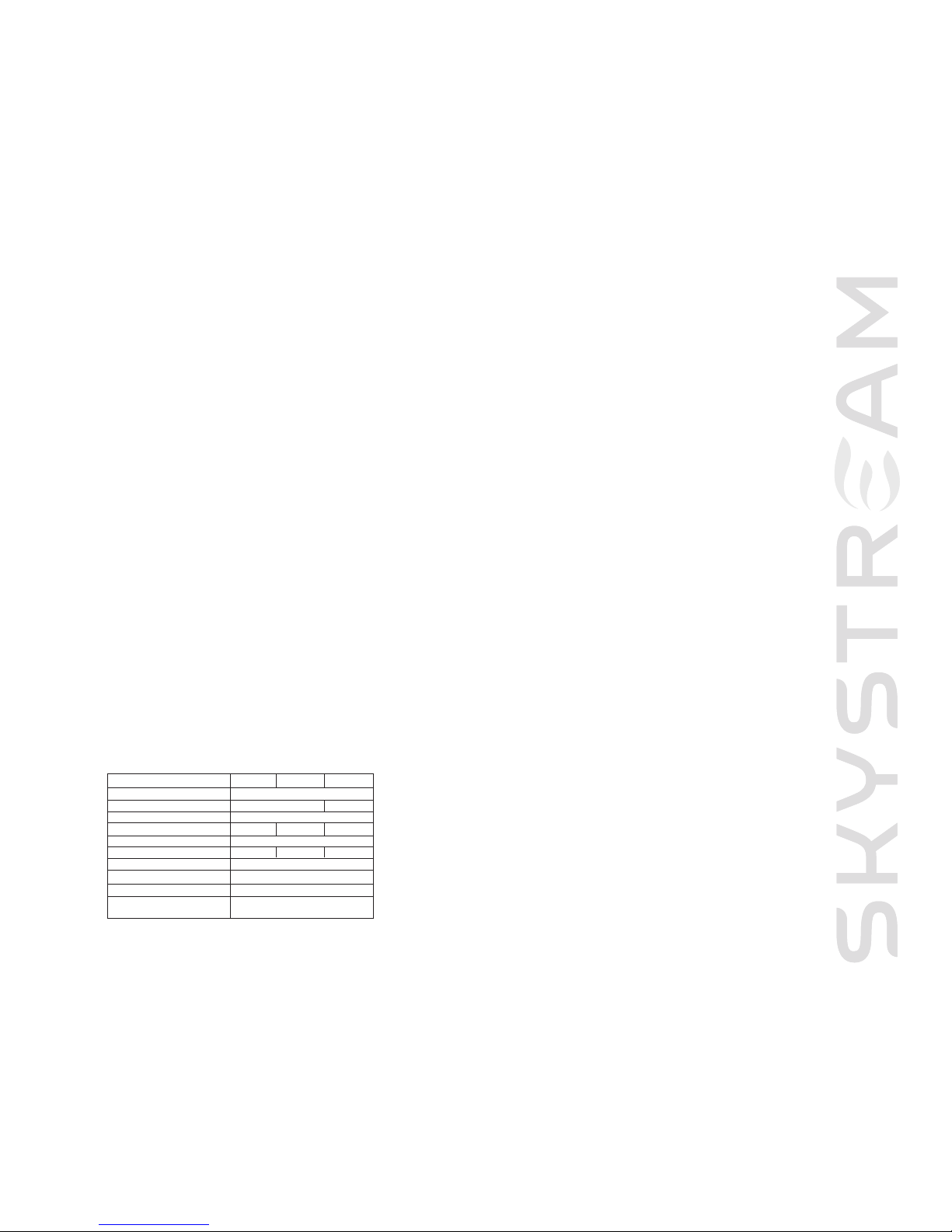
configuration 120/240V 120/208V 240V
output power factor rating 1.0
operating voltage range (ac) 106-132V l-n 212-264V
operating frequency range 59.3-60. 5 Hz
nominal output voltage (ac) 240V 208V 240V
normal output frequency 60 Hz
max continuous output current 7.5 A 8.7 A 7.5A
rated output power 1800W
peak output power 2400W
software revision 1.0.00
max ambient temperature 50C. output power is reduced
above 60 C. nacelle temperature
Page 7

SOUTHWEST WINDPOWER SKYSTREAM 3.7 OWNER’S MANUAL
6
Your Skystream shipment includes:
Your Skystream shipment includes the following components. A spare of each fastener (bolt, washer or nut) is included. The quantities
indicated below are quantities required to assemble Skystream:
RF Antenna
Loctite®242
Turbine assembly with blade hub, retaining nut, blade plate
and nosecone
Blades and blade mounting hardware
l
M10-1.5 x 120 socket head bolts, grade 12.9 (quantity 12)
l
M10-1.5 nuts, grade 12.9 (quantity 12)
l
M10 flat washers, A2 stainless steel (quantity 12)
l
M10 lock washer, A2 stainless steel (quantity 12)
l
Blade plate
l
Blade hub
l
M42, hub nut
Nose cone with mounting hardware
l
M6-1.0 x 12 socket head bolts, grade 8.8 (quantity 3)
1-2 Recommended Tools
You will need the following tools to complete assembly of Skystream and install on the tower:
l
Crescent wrench up to 40 mm
l
17, 24, 33, 36 & 50 mm hex wrenches
l
19 mm hex wrench and socket for torque wrench
l
Wire stripper
l
Phillips head screwdriver
l
Flat blade screwdriver and socket for torque wrench
l
Multi-meter
l
Torque wrench, 0-100 lb-ft (135 N-m)
l
Torque wrench, 0-50 lb-inch ( 5.6 N-m)
Yaw vibration isolators with mounting hardware
l
Vibration Isolators (quantity 8)
l
M12-1.75 x 90 hex head bolt, grade 10.9 (quantity 8)
l
M12-1.75 nuts, grade 10.9 (quantity 8)
l
M12 flat washers, A2 stainless steel (quantity 8)
l
M12 lock washers, A2 stainless steel (quantity 8)
l
M12 snubbing washers (quantity 8)
Yaw shield (two halves) with mounting hardware
l
M5-0.8x12 button head screws (quantity 4)
Strain relief cover assembly with mounting hardware
l
Strain relief cover with ground wire
l
M5-0.8 x 12 socket head bolt (quantity 4)
l
M5 lock washer A2 stainless steel (quantity 4)
TIP: See exploded view
on pages 16-17
Note: This list does not include tools you will need for the construction of the tower or wire trench.
Page 8

SOUTHWEST WINDPOWER SKYSTREAM 3.7 OWNER’S MANUAL
7
1-3 Skystream Options
There are a number of options that can enhance the experience of using a Skystream wind appliance. Although your Skystream will
operate without them, we suggest reviewing this chapter. Contact Southwest Windpower or your dealer if you have questions.
T
M
remote interface
escape
enter
status
www
.skystr
eamenerg
y
.com
Remote Display
The optional remote display allows you to observe
Skystream’s performance in real time.You can also collect
data such as kWh per day, per month and per year. The
display wirelessly connects via a 900 MHz frequency and
works up to 1000 feet from the tower.
USB Converter ä
The USB converter allows
you to connect the remote display to your computer and monitor Skystream
real time. Specialized software allows you to create your own power curves,
monitor performance remotely and even download and transmit the latest
software directly to your Skystream to maximize performance.To connect
Skystream to your computer, you must also use the wireless remote.
Tower Adaptor
The tower adaptor allows
you to attach your Skystream
to a tower constructed of
5 inch schedule 40 pipe.
Nominal internal diameter
of 5 inch (12.7 cm).
Remote Monitoring
There are a number of benefits to remote monitoring. A
subscription to Fat Spaniel Technology allows a third party
company to monitor the performance of your Skystream
and communicate with a local dealer in the event there is a
problem. Additionally, for states with “green tags” you could
receive added revenue for each kWh your Skystream
produces. Contact your dealer or Southwest Windpower
directly for more information.
ä
ä
SouthwestWindpower
Renewable Energy Made Simple
1801 W. Route 66 • Flagstaff, AZ 86001
p
h 928.779.9463 fax 928.779.1485
www.windenergy.com
U
SB
RS485
MODEL 3-CMLB-1037
Page 9
SOUTHWEST WINDPOWER SKYSTREAM 3.7 OWNER’S MANUAL
8
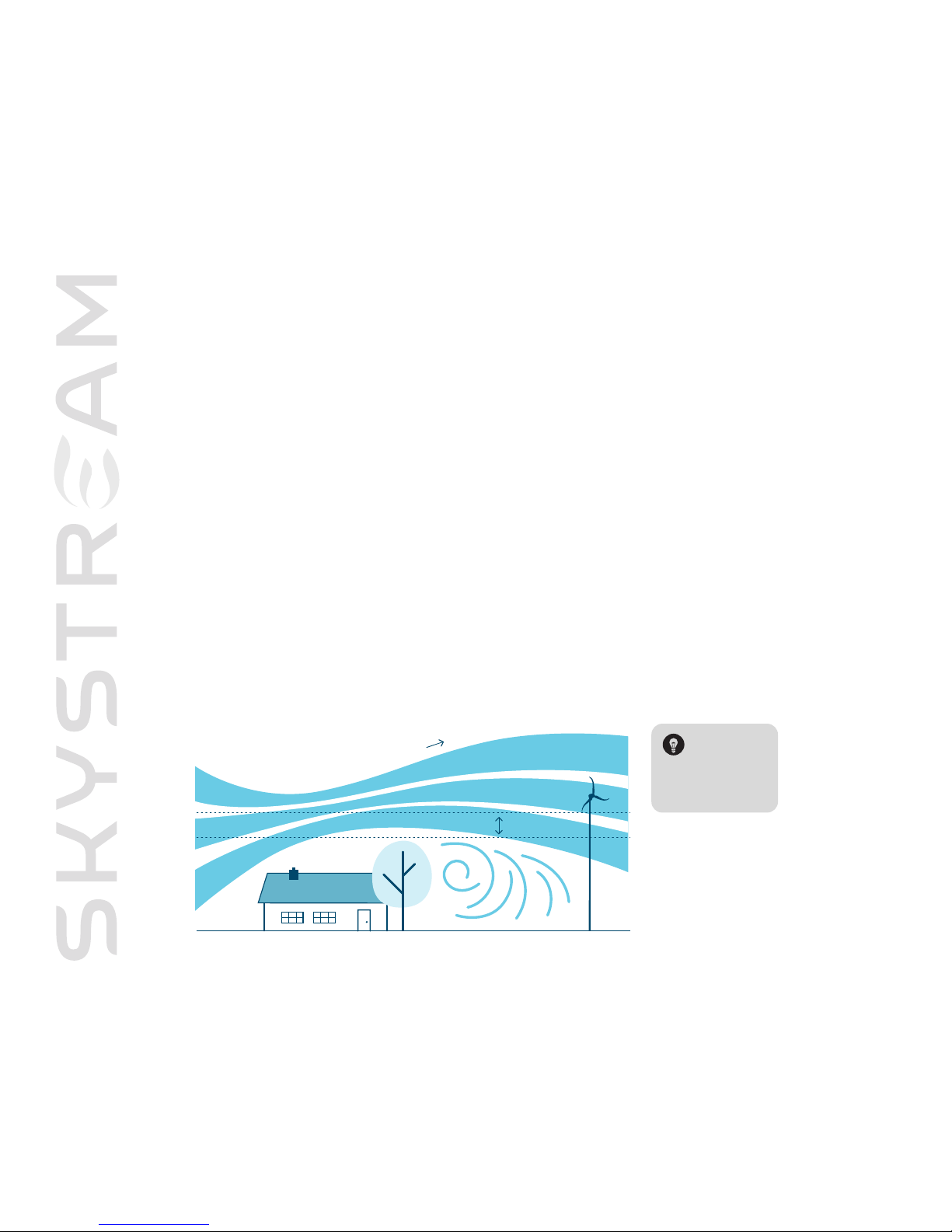
1-4-1 Finding the Best Location for Your Skystream
We have worked at simplifying the installation process of Skystream, but each installation is likely to be different. Skystream
may require a different tower depending on trees, obstructions and soil types.
Very Important: Proper siting is essential to a well performing wind generator.
The taller the tower, the more energy your Skystream will produce but keep in mind, this will also increase the cost of the
installation. It is extremely impor tant to balance performance (tower height) to installed cost in order for you to achieve
the lowest cost of energy and quickest payback. Also, keep in mind zoning regulations that may restrict the height of your
tower. See section 1-4-4 regarding zoning.
Our General Rule: For optimal performance, Skystream should be 20 feet (7 m) above any surrounding object within a
250 foot (76 m) radius.
20 feet
w
ind dire ction
1-4 Skystream Project Preparation
There are several considerations before you begin the installation process of your Skystream.These considerations
are more important if you intend to connect your machine to the electrical utility. Although Skystream is UL and IEEE
certified, your local utility and zoning authority may require additional information prior to installation.This chapter
will provide an overview of what to expect when working with your zoning authority and utility. Southwest Windpower
has a number of resources that may assist you in the permitting and interconnection processes.
To learn more go to: www.skystreamenergy.com
TIP: Your dealer
can help you
determine the
best location for
Skystream on
your property.
Fig. 1 Optimal Skystream location
Page 10
SOUTHWEST WINDPOWER SKYSTREAM 3.7 OWNER’S MANUAL
9
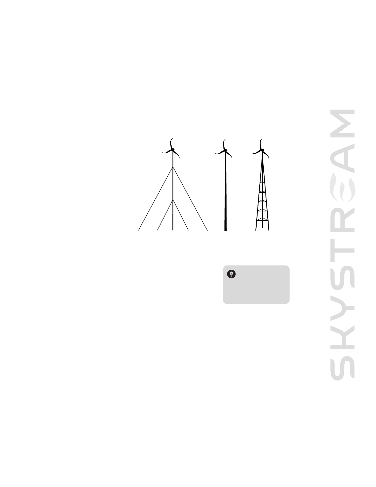
guyed tower
monopole tower lattice tower
1-4-2 Tower Types
Depending on your site needs, Skystream can
be mounted on several different tower types as
long as they meet the tower load specifications
determined by Southwest Windpower and are
certified by a Professional Engineer (PE). While
a guyless monopole tower is the most desired
tower type, it may be more expensive than
some other options such as a guyed tower
or latticed tower. You can find out more
about available tower options provided
by Southwest Windpower at
www.skystreamenergy.com.
1-4-3 Working With Your Utility
Call your local electric utility, tell them your intentions and ask for their “interconnection
agreement”.They should have one. Depending on your utility, the interconnection agreement
may be one page or many. Keep in mind that small utility-connected solar and wind
systems are relatively new industries and utility connection requests may be unfamiliar to
them. If you are the first, realize the process may take longer. Southwest Windpower has
people and tools that may assist in the process.
Your utility may request documentation demonstrating that Skystream is UL 1741 certified.
You can download these at our website: www.skystreamenergy.com
1-4-4 Working With Your Local Zoning Authority
Like your utility, the local planning and zoning authority may or may not have experience with an individual installing a small wind
generator at their home or small business.The most important issue is the height of the tower. Prior to purchasing your Skystream
to
wer, check for local zoning limitations. Determine what your community allows for towers and determine if the height is appropriate.
Specific data and statistics that may be required by your zoning authority can be found at www.skystreamenergy.com.
TIP: See our website:
www.skystreamenergy.com
for a sample interconnection
agreement that may be used
by a utility that has yet to
establish a program.
Fig. 2 Tower types
Page 11

SOUTHWEST WINDPOWER SKYSTREAM 3.7 OWNER’S MANUAL
10
Two - Installation
Southwest Windpower designed the installation process of Skystream to be as easy as possible by minimizing the number of connections
between the machine and circuit breaker. Depending on your local utility requirement, you may or may not need to install a separate
disconnect and/or second meter.
You will notice the rotor shaft on Skystream is extremely difficult to turn.This is normal. As a safety precaution, the default position of
Skystream is in brake mode when the inverter is disconnected from the utility-supplied power.The reason is if there is a fault in the utility
line, Skystream must shut down to prevent back feeding of electricity into the line while it is being repaired.
2-1 Electrical
One of the most common causes of wind generator failures is a poor electrical connection. Be sure to follow the instructions and tighten
all fasteners appropriately.
IMPORTANT: It is extremely important that the installation of your Skystream is done in accordance with local and national building
codes as specified by the NEC, UBC (Uniform Building Code) or IBC (International Building Code).These codes will vary from city to
city and even country to countr y.
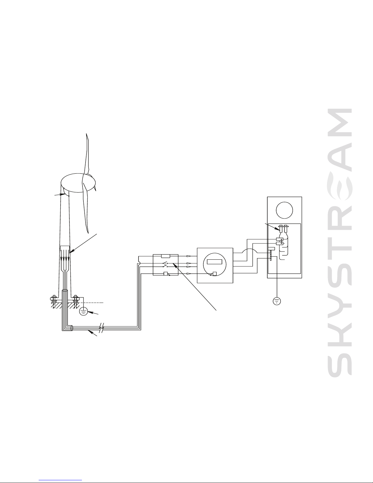
2-1-1 Wiring
Skystream has a built-in utility-connected inverter compliant with UL 1741.This means Skystream connects directly to your existing
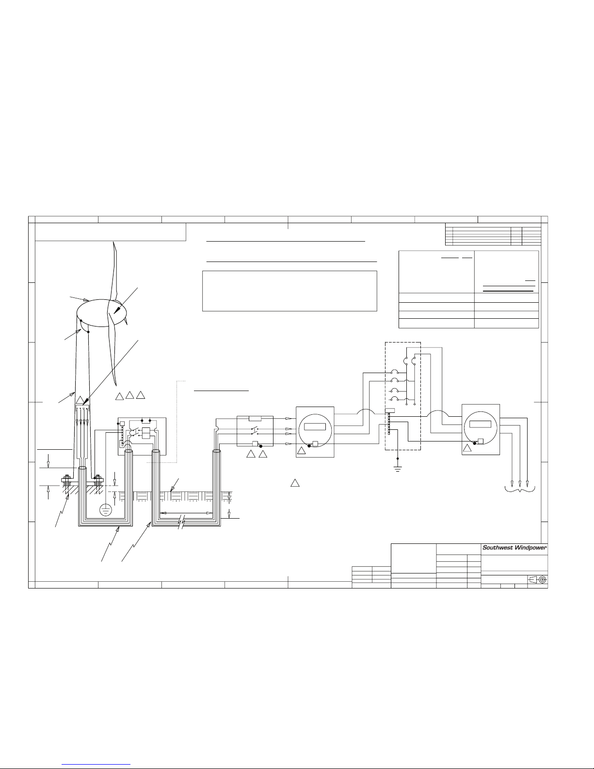
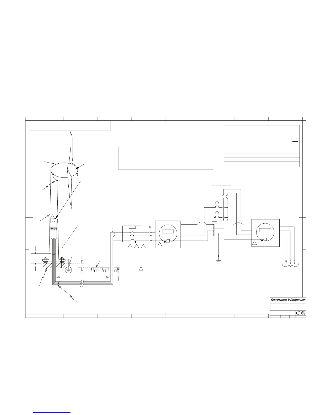
electrical system. Appendix A includes two reference drawings for utility-supplied power interconnection of your Skystream generator.
These drawings are for reference and may be modified for submittal and approval by your local authorities.
Refer to Fig. 3 on the opposite page for a complete overview of Skystream wiring.
Warning: For your safety,
make sure power is turned off
before working on any and all
electrical connections.
Page 12
SOUTHWEST WINDPOWER SKYSTREAM 3.7 OWNER’S MANUAL
11
LL
1
1
GG
NN
LL
22
Fig. 3 Wiring diagram
Yaw ground wire
Yaw connectors. See Fig. 4 (page 12)
AC Service Panel
Disconnect
switch 2-pole
30A, 250VAC
Optional
kilowat-hour
meter
Main disconnect
NNoottee:
:
Refer to appendix for detailed wiring drawings
White
Black
Red
Bare or green
Tower ground
system (optional)
N
L1
L2
GNL2L1
N/G
G
2200A
A
Use only copper wire at the generator terminals
Aluminum wires may be used for home/utility
connection if transition is made in junction box.
14 AWG wire must be copper only.
N
L1
L2
Gnd
2200A
A
Page 13
SOUTHWEST WINDPOWER SKYSTREAM 3.7 OWNER’S MANUAL
12
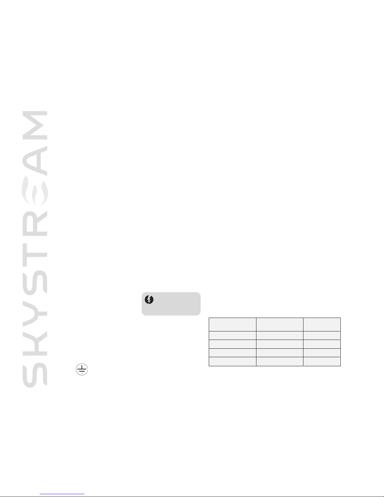
Fig. 4 Wire run to the yaw connection
Distance AC Service Panel
to Tower Top
AWG
American Wire Gauge
Metric Wire Size
(mm2)
8 AWG
10 AWG
12 AWG
14 AWG
315 feet (92 m)
198 feet (56 m)
125 feet (37 m)
79 feet (23 m)
10 mm
2
6 mm
2
4 mm
2
2.5 mm
2
Ground: green
or bare copper
Line 2: red
Neutral: white
Line 1: black
UUssee ccooppppeerr ccoonndduuccttoorrss oonnllyy -- MMiinniimmuumm wwiirree tteemmppeerraattuurree rraattiinngg iiss 7755°°CC ((116677°°FF)
)
Wiring Symbol Definitions
LL11
= Line 1, AC Line Voltage, Black Wire
LL22
= Line 2,
AC Line Voltage, Red Wire
NN
= AC Neutral, White Wire
GG
= Gnd. = AC Ground, Green or Bare Wire
Indicates AC Ground
2-1-3 Wire Sizing
Measure distance from AC Service panel to Skystream (be sure to
include tower height). Refer to the accompanying wire chart and
select the appropriate gauge wire. Indicated wire sizes will include
length from top of tower to connection at main utility panel.
CAUTION – Be sure power is turned off when
making electrical connections.
l
Position Skystream on its side to access the wire terminals.
l
Remove approximately 2 inches (5 cm) of protective
sheathing from cable and strip approximately 0.375 inches
(1 cm) of insulation off wire leads.
l
Pass cable through strain relief cover so approximately
1 inch (2.5 cm) of cable sheath protrudes through as
shown in Fig. 4 at right. Tighten strain relief clamp to
secure cable.
l
Connect the red, black, and white wires to the matching
color coded terminals on Skystream yaw assembly.
Connect the green or bare copper wire to the green terminal.Tighten each screw to 20-25 inch-lbs (2.3-2.5 N-m).
Before attaching the strain relief cover, test the electrical connections by turning on power and measuring voltage at the
yaw terminals. Additionally, with AC power switched on, wait 57 minutes and attempt to rotate the blade shaft.The shaft
should be noticeably easier to rotate.Turn off power and
Skystream should revert to “brake” mode. If Skystream fails this
test, check all connections and repeat test.Test must be passed
before proceeding.
l
Turn power off and secure
strain relief cover using
four M5-0.8 x 12 socket
head screws and split
lockwashers. Use Loctite
®
242 and torque screws to 20-25 inch-lbs (2.5 N-m).
2-1-2 Electrical Connections
Caution: Make sure AC
power is switched OF F
before proceeding with
installation
Page 14
SOUTHWEST WINDPOWER SKYSTREAM 3.7 OWNER’S MANUAL
13
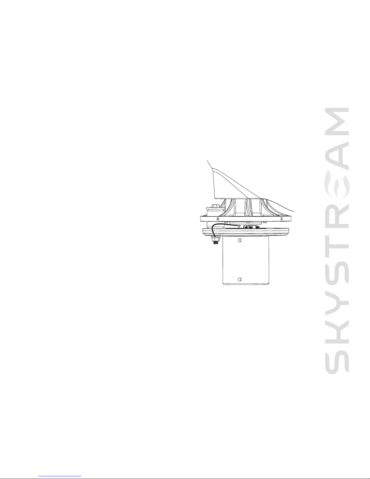
2-1-4 Grounding
Every electrical system must be grounded in accordance with local and national
standards.This will provide some protection against voltage surges and built-up
static charges (see reference drawings in Appendix A).
Section 810 of the National Electrical Code ANSI/NFPA No. 70 (USA only)
provides information with respect to proper grounding of the tower, size of the
ground wire, type of discharge unit, size of grounding conductors, location of
discharge unit, connection to grounding electrodes and requirements for the
ground electrode.
Note: The AC output neutral is NOT bonded to ground within Skystream.
AC neutral is bonded to ground at AC distribution panel.
The instructions in this section are for reference only as the
requirements in your area may be different.
2-1-5 Fusing/Circuit Breaker
Skystream connects directly into your electrical panel. Wiring will vary with local
zoning authority and utility (see reference drawings in Appendix A). Some
installations will require a visible lockable disconnect switch located next to
the electrical meter and/or at the base of the tower. The disconnect switch
is utilized by your local utility in the event of a power outage to ensure no
voltage is placed on the utility line during repair.Again, it is extremely important
to install in accordance with local and national zoning regulations.
Note: Only 20 Amp circuit breakers may be used to connect Skystream to AC
service panel. Refer to Fig. 3, wiring diagram.
2-1-6 Checking correct grid connectivity
IMPORTANT: All electrical connections should be completed
before testing.
To check for correct connections:
l
Check that all connections are complete.
l
Switch on all of the disconnects between the turbine and the utility power.
l
Wait for 5-7 minutes.
l
Check that the rotor spins free.
l
Important: Disconnect the turbine from utility power.
l
Check that the rotor no longer spins free.
Fig. 5 Proper grounding of the yaw connection
Page 15
SOUTHWEST WINDPOWER SKYSTREAM 3.7 OWNER’S MANUAL
14
1 ½ feet
(46 cm)
1 foot
(30 cm)
S
tub tower
N
ot t
o e
xceed
7 f
eet (213 cm)
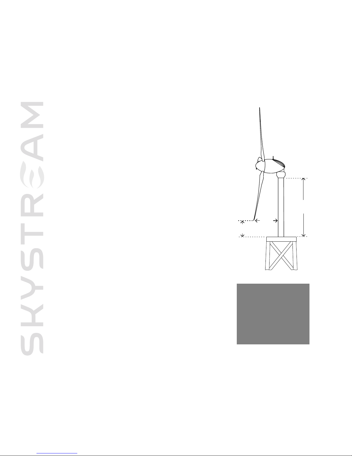
2-2 Installing Skystream on a Tower
There are several types of towers that can be used with Skystream. It is essential that
Skystream is installed on a properly engineered tower. One of the leading causes of
wind generator failure is use on a poorly designed tower.
Southwest Windpower has made available various tower designs that meet our
criteria. We have established a program allowing tower manufacturers to include their
designs on Southwest Windpower’s website list of recommended towers.
Regardless of the tower design and height you select, there are two critical areas that
must be considered when selecting the tower.These are the stub tower height and
blade clearance (see Fig. 6).
Fig. 6 Blade tip clearances
IMPORTANT: Southwest
Windpower’s Warranty is
only extended to installations
that are made on a properly
engineered tower. Southwest
Windpower reserves the right
to deny any warranty claim in
which a
n impr
operly designed
tower is used.
Page 16
SOUTHWEST WINDPOWER SKYSTREAM 3.7 OWNER’S MANUAL
15
2-2-1 Mounting Skystream to the Tower
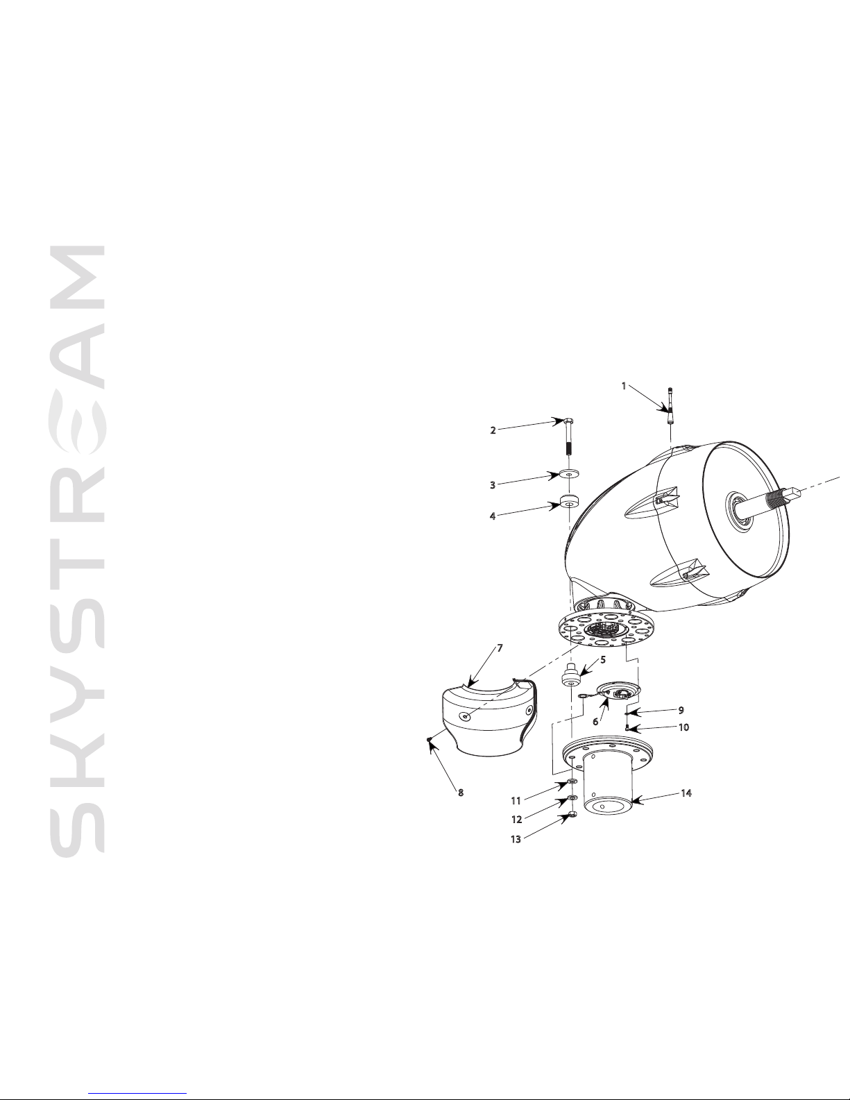
Refer to Fig. 7 (page 16) for visual aid.
Note: The following directions assume Skystream will be bolted to tower on ground and tower will be tilted into position. Alternately
Skystream may be completely assembled on the ground and “hoisted” into position.
To ease mounting Skystream, support the upper end of the tower approximately 2-3 feet (0.6-1.0 m) above the ground.
l
Install the vibration isolators on yaw flange as shown in Fig. 7 (page 16). Install snubbing washers and bolts in vibration isolators.
Note: The orientation of the vibration isolators is very impor tant. Refer to Fig. 7.
l
Using an appropriate lifting device and sling, lift Skystream and align vibration isolator bolts with holes in tower flange.
l
Install nuts, flat washers and lock washer on bolts to secure Skystream to tower.
l
Torque vibration isolator bolts to 80 lb-ft (108 N-m) in two steps. First torque all bolts to 40 lb-ft (54 N-m) then to 80 lb-ft (108 N-m).
l
Mount yaw shield halves using four M5 button head screws. See Fig. 7 (page 16). Use Loctite®242 supplied with Skystream.
2-3 Testing on the Ground
Though Skystream is thoroughly tested at the factory, it is very important to conduct one more test prior to erecting the tower.
Skystream should be wired and mounted to the top of the tower.The blades should not be attached.To do this test, you must have all
wires and breakers installed with at least one disconnect switch open (off).
2-3-1 Electrical Test
l
Attempt to rotate the rotor shaft. It should be difficult to turn.
l
Now turn on all power going to Skystream.Turn on all breakers, connect all switches and wait 5-7 minutes.
l
Grab the rotor shaft again and try to spin it. If assembled correctly, it should spin easily.
l
Before you go any further, turn the power off and disconnect any switches. Again, try spinning the shaft. It should be difficult to turn.
If Skystream does not spin freely after electrtical test, then check for loose or disconnected wires. Repeat the test until you are successful.
Warning: Working on towers is dangerous
and should be left to professionals with proper
safety equipment and training.
Page 17
SOUTHWEST WINDPOWER SKYSTREAM 3.7 OWNER’S MANUAL
16
2
3
4
7
5
6
8
10
11
12
13
15
16
17
18
19
20
21
23
22
24
14
1
9
Refer to Fig. 8 (page 17) for visual aid.
The Skystream blades may be bolted to the blade hub
and mounted on Skystream as a complete assembly by
performing the following steps.
l
Remove the blade mounting hub and plate from
Skystream by “unscrewing” the hub while holding the
rotor shaft stationary.
l
Place a blade between the blade hub and blade
mounting plate. Refer to Fig. 8 (page 17) for proper
orientation.
NNoottee:
:
the blades may only be installed in
one position due to the “triangular” boss cast into one
side of the blade root (base).
l
Loosely install the bolts, flat and lock washers for one
blade leaving enough play so remaining blades can be
installed.
l
After all blades and bolts are loosely installed between
blade hub and mounting plate, tighten bolts enough to
clamp blades between hub and blade plate.
l
Torque blade bolts to 50 lb-ft (68 N-m) in two steps.
First torque all bolts to 25 lb-ft (34 N-m) then to 50
lb-ft (68 N-m).
l
Blade assembly may now be mounted on Skystream.
Slide blade assembly completely onto shaft.With
assembly completely on shaft, large mounting nut can
be started on shaft threads.
l
Completely “spin” on blade assembly. Securely tighten
blade assembly by holding blades and tightening “flat”
on rotor shaft.
NNoottee:
:
the blade assembly is self-tightening
in operation; however it should be securely tightened
during assembly (200lb-ft).
l
Install nosecone with three M6-1.0x12 socket head
bolts. Use Loctite®242 supplied with Skystream.
l
Install RF Antenna on matching fitting on top of
Skystream. Finger-tight is sufficient.
Impor
tant: Do Not Forget to install RF Antenna
Even if you have not purchased the optional remote display,
the RF antenna may be used by service personnel to
diagnose
,
troub
leshoot or upgr
ade your Skystream
without removing it from the tower.
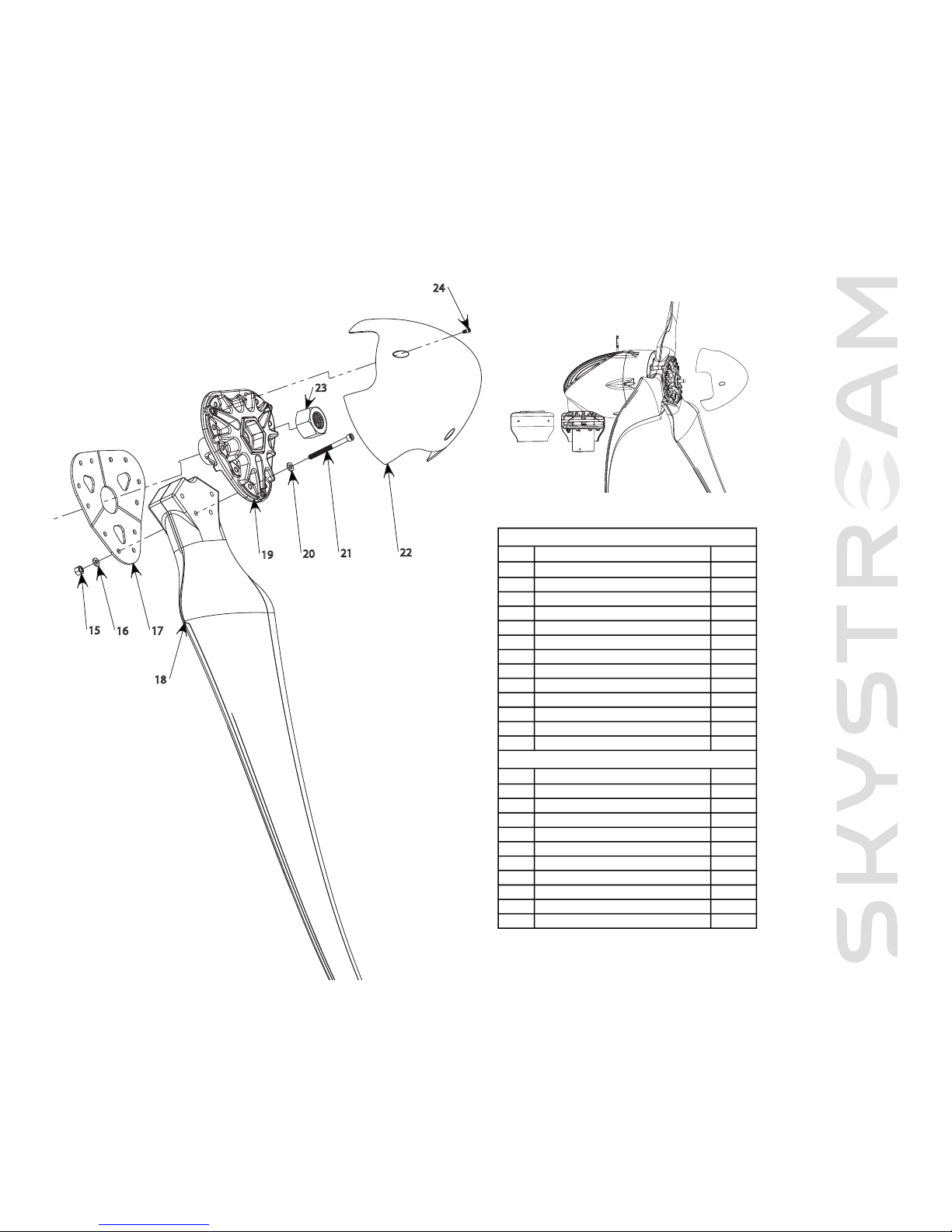
2-4 Blades, Nosecone and Antenna Assembly
Fig.
7
Y
a
w and antenna assembl
y
Page 18
SOUTHWEST WINDPOWER SKYSTREAM 3.7 OWNER’S MANUAL
17
15
16
17
18
19
20
21
23
22
24
Fig. 9 Completed assembly
# Description Qty.
1 RF Antenna 1
2 M12x1.75x90mm Hex Bolt grade 10.9 8
3 Snubbing Washer 8
4, 5 Vibration Isolation Ring (4) and Bushing (5) 8
6 Strain Relief Cover Assembly 1
7 Shield 2
8 M5x.8x12mm Button Head grade 8.8 4
9 M5 Lock Washer A2 stainless steel 4
10 M5x.8x12mm Bolt SHCS grade 8.8 4
11 Flat Washer (M12) A2 stainless steel 8
12 Lock Washer (M12) A2 stainless steel 8
13 M12x1.75 Nut grade 10.9 8
14 5" Tower Insert 1
# Description Qty.
15 M10x1.5 Nut grade 12.9 12
16 Lock Washer (M10) A2 stainless steel 12
17 Blade Plate 1
18 Blade 3
19 Blade Hub 1
20 Flat Washer (M10) A2 stainless steel 12
21 M10x1.3x120mm Bolt SHCS grade 12.9 12
22 Nose Cone 1
23 Hub Retaining Nut grade 10.9 1
24 M6x1x12mm Bolt SHCS grade 8.8 3
Yaw Components
Blade Components
Fig. 8 Blade and nosecone assembly
(optional)
Page 19

SOUTHWEST WINDPOWER SKYSTREAM 3.7 OWNER’S MANUAL
18
Three - Operation & Maintenance
3-1 Skystream 3.7™ Key Operating Characteristics
The Skystream 3.7 operates by converting the kinetic energy of the wind into rotational motion that turns an alternator and ultimately
produces usable electric power. In actuality this is a great over simplification of Skystreams operation since it must very precisely match
the frequency and voltage of the electricity supplied by the local utility company in order to power your home and its appliances.
Additionally Skystream monitors and adjust its performance to provide safe operation and extract the maximum energy from even low
speed winds.
Skystream will begin producing power in a wind of approximately 8 mph (3.5 m/sec).At that speed the blades will rotate at approximately 120 rpm. As the wind speed increases the blade speed will also increase until at about 20 mph (9 m/sec) wind speed the blade
speed achieves a rotational speed of 325 rpm.This is Skystreams rated speed. Should the wind speed increases above 20 mph the blade
speed will remain fixed at 325 rpm.
If a condition occurs that causes the rotational speed to exceed 360 rpm, Skystream will shut down for approximately 10 minutes after
which it will resume normal operation unless a fault is detected causing it to remain shut down. This is an unlikely scenario that should
never occur in normal operation.
As the wind speed exceeds 25 mph Skystream enters a reduced power mode marked by lower power production and reduced blade
speed. Should the wind speed continue to increase and achieve 65 mph Skystream will assume storm conditions exist and shut down
for one hour. After one hour Skystream will restar t operation in the reduced power mode. It will remain in reduced power mode until
it determines that the wind speed has returned pre-storm levels at which time it will resume normal operation.
In addition to adjusting its operation in response to wind conditions Skystream also monitors the electrical utility grid and its own internal health. Should the electric utility voltage or frequency differ from Skystream’s voltage, for example due to a power failure, Skystream
will disconnect from the grid and enter a “braked mode”.While in this mode the blades are held stationar y while the Skystream monitors the utility power. If Skystream determines that the power has returned to within specification, it will re-connect to the grid and
resume normal operation. This is the same cycle that occurs when Skystream is initially powered.
Additionally, should Skystream determine an internal fault exists it will execute an emergency shutdown – an E-stop. An E-stop will only
take place if a severe fault that requires servicing internal components has occurred. For that reason resetting an E-stop requires gaining
access to the interior of Skystream. It cannot be reset from the ground.
As a final note
, Skystream is factory configured for operation up to 1000 meters (3,300 feet) above sea
level. If your installation exceeds this elevation please consult Southwest Windpower technical service
for assistance in resetting the configurations for your elevation.
Page 20

SOUTHWEST WINDPOWER SKYSTREAM 3.7 OWNER’S MANUAL
19
SOUTHWEST WINDPOWER SKYSTREAM 3.7 OWNER’S MANUAL
3-2 Frequently Asked Questions
1) What happens if I lose power from my utility company?
If there is a power outage the Skystream will shut down within one second. It will resume normal operatio when power is restored.
There are many safety requirements of a utility-tied inverter.The Skystream meets all of these requirements per UL 1741.
2) Does the Skystream have lightning protection?
Yes the Skystream has lightning protection.The Skystream can handle 6000 Volts as required by UL 1741. If you live in a lightning prone
area SWWP recommends an additional lightning arrestor at the base of the tower.
3) What should I do if I’m expecting a severe storm?
The Skystream is designed for very high winds, but it is always a good idea to shut Skystream down if there is going to be a severe
storm to protect against any flying debris.
4) How do I shut down Skystream?
To turn off Skystream all you need to do is turn off the breaker Skystream is connected to.This will cause NO damage to the unit.
5) Can I leave Skystream unattended?
Yes, the Skystream is designed to operate without any user input. If there is any fault it will shut down on its own.
6) What do I do if Skystream is facing upwind even though there is a strong wind?
If the Skystream is not tracking correctly, then you should check to see if the tower is level.
7) When should I contact an authorized service technician?
a. If there is any unusual vibration coming from Skystream.
b. If you hear any noise that sounds like mechanical interference.
c. If the Skystream is connected to the utility power (i.e. all breakers and disconnects are turned on), the wind is blowing, but
the Skystream is not turning very fast.
8) Can I mount Skystream to my roof?
Roof and building mount is not recommended. Because of the size and weight of the wind generator, Skystream needs to be mounted
on a PE certified tower to ensure the quietest and safest system. Roof mounting will invalidate the warranty.
Page 21

Appendix A
Electrical Connection Diagram Options
Page 22
P. Thomas
18 Aug '0 6
XE
8/9/06
POT
8/18/06
POT
Added notes, more wire sizes
X
F
Changeddraw ing title
XG Updatecircuit breaker schematic
10/10/06
POT
Proprietary rights are included in the information disclosed herein. This information is
s
ubmitted in confidence and neither the document nor the information disclosed herein shall be reproduced or transferred to other documents fo r manufacturing or for any
o
ther purpose except as specifically authorized in writing by Southwest Windpow er.
D
E
F
C
21
3
4
B
A
32
1
5
C
D
4
6
7
8
A
B
D. Calley
18 Aug '0 6
Skystream_home_grid_connect_08182006_revXG
N.Agrawal
1-STL-10-1
Skystream
18 Aug '0 6
Flagstaff, Arizona U.S.A.
CAD-generated drawing
do not manually update
scale none
size A3
dwg. n°
sheet 1 of 2
rev. XG
DATE
APPROVALS
DRAWN
CHECKED
RESP ENG
MFG ENG
QUAL ENG
Unless otherwise specified
dimensions are in mm.
tolerances are :
distances angles
X. ± .5 ± 30 '
.X ± .2
.XX ± .1
MATERIAL
FINISH
--
-
DO NOT SCALE DRAWING
APPLICATION
USED ON
NEXT ASSY
E
POT
3/09/06
E
ngineering release
X
D
P
OT
2/23/06
Engineering release
X
C
REVISIONS
REV.
D
ESCRIPTION
D
ATE
A
PPROVED
-
Skystream home grid
interconnect
5
G
N
4
240VAC 3-#10 AWG THWN-2
1-#10 AWG THWN-2 GND
FOR <153 FEET SPAN BETW'N
TOWER BASE J-BOX
TO AC
MAIN SERVICE PANEL; FOR
LARGER SPANS USE
APPROPRIATE AWG.
DEDICATED WIND
POWER SYSTEM
KILOWATT-HOUR
METER
(OPTIONAL)
N
G
L1
L2
FROM UP-TOWER
YAW JUNCTION BOX
240V AC SPLIT PHASE
60Hz, #10-3 UF-B
DIRECT BURIAL CABLE
W/ GROUND (TOTAL 4
CONDUCTORS)
L1
L2
UTILITY
KILOWATT-HOUR
METER
G
L1 (black)
L2 (red)
N (white)
WIND POWER
SYSTEM
DISCONNECT
SWITCH 2-POLE
30A, 240VAC
SQ-D #DU221RB
L1
L2
N
"SKYSTREAM"
WIND TURBINE
G
5
6
3
15 FT.
8
AWG
1
0AWG
198 FT.
SPAN BETW'N TOWER
TOP
T
O AC MAIN SERVICE
P
ANEL FOR COPPER WIRE
ONLY, ASSUMING GRID
V
OLTAGE IS 220V,
T
URBINE PUTS OUT 1.9kW
AND TOWER HEIGHT 35FT
U
SABLE AWG FOR 2%
POWER LOSS (FOR
L
INE AND NEUTRAL
C
ONDUCTORS ONLY
)
125 FT.
12 AWG
14 AWG
79 FT.
*
N/G
GND (bare/green)
40 A
40 A
20 A
20 A
AC MAIN
SERVICE
PANEL
240 VAC
TO SERVICE
TRANSFORMER,
UTILITY GRID
THIS DRAWING IS FOR REFERENCE
TOWER
GROUND
SYSTEM
ELECTRICAL CONNECTION OPTION #1
CONNECTION TO HOME / UTILITY
WITH JUNCTION BOX AT TOWER BASE
TOWER
FOUNDATION TOP
SURFACE TO BE
MIN. 6" ABOVE
GROUND LVL.
REFER TO SWWP
FOUDATION DWG.
1" DIA. SCHED. 40
RIGID PVC CONDUIT;
SUNLIGHT RESISTANT;
UL LISTED
SAFETY SWITCH
2-POLE, 30A, 240VAC,
SQUARE D #DU221RB
AT TOWER BASE
RUN FROM JNC. BOX AT
TOWER BASE TO HOME
24 INCH MIN.
GROUND
LEVEL
NACELLE
CHASSIS
ELECTRICALLY
CONNECTED
TO YAW, WHICH
MUST BE
ELECTRICALLY
CONNECTED TO
THE TOWER
NACELLE
TOWER
(APPROX.
35 FT.
HIGH)
12 INCH MAX.
10 INCH MIN.
VARIATIONS MAY BE MADE IN
ACCORDANCE WITH NEC GUIDELINES
6" MIN.
NOTES:
1. EQUIPMENT SHALL BE INSTALLED IN ACCORDANCE WITH NEC ARTICLE 705.
2. PROVIDE WARNING SIGN PER NEC 690-17 READING "WARNING-ELECTRIC
SHOCK HAZARD-DO NOT TOUCH TERMINALS - TERMINALS ON BOTH THE LINE
AND LOAD MAY BE ENERGIZED IN THE OFF POSITION".
3. LABEL "WIND POWER SYSTEM DEDICATED kW-HR METER".
4. LABEL SWITCH AS "WIND GENERATOR SAFETY DISCONNECT SWITCH;
REMOVING AC POWER TO TURBINE ACTIVATES ITS SAFETY BRAKE".
5. OPTION IS TO USE A JUNCTION BOX AT TOWER BASE INSTEAD OF A SWITCH.
6. LABEL "REMOVING AC POWER TO TURBINE ACTIVATES ITS SAFETY BRAKE".
7. BI-DIRECTIONAL METER TO BE INSTALLED BY UTILITY (WHEN REQUIRED).
8. USE COPPER WIRES ONLY AT TURBINE TERMINALS
9. ALUMINUM WIRES MAY BE USED FOR HOME / UTILITY CONNECTION IF TRANSITION
WERE DONE IN A JNC. BOX. 14AWG WIRE MUST BE COPPER ONLY.
L
1
L2NG
GROUND
SYSTEM
9
2
7
8
3
Option 1:
EElleeccttrriiccaall ccoonnnneeccttiioonn ttoo hhoommee//uuttiilliittyy wwiitthh jjuunnccttiioonn bbooxx aatt ttoowweerr bbaassee..
1
Page 23
2
N
L2
L1
WIND POWER
SYSTEM
DISCONNECT
SWITCH 2-POLE
30A, 250VAC
SQ-D #DU221RB
N (white)
L2 (red)
L1 (black)
G
BIDIRECTIONAL
UTILITY
KILOWATT-HOUR
METER
L2
L1
G
N
DEDICATED WIND
POWER SYSTEM
KILOWATT-HOUR
METER
(OPTIONAL)
4
G
*
FROM UP-TOWER
YAW JUNCTION BOX
240V AC SPLIT PHASE
60Hz
7
9 FT.
14 AWG
12 AWG
1
25 FT.
U
SABLE AWG FOR 2%
POWER LOSS (FOR
L
INE AND NEUTRAL
CONDUCTORS ONLY )
S
PAN BETW'N TOWER
T
OP
TO AC MAIN SERVICE
PANEL FOR COPPER WIRE
ONLY, ASSUMING GRID
V
OLTAGE IS 220V,
TURBINE PUTS OUT 1.9kW
AND TOWER HEIGHT 35FT
GND (bare/green)
N/G
7
198 FT.
10 AWG
8
AWG
315 FT.
"SKYSTREAM"
WIND TURBINE
20 A
20 A
40 A
40 A
TOWER
(APPROX.
35 FT.
HIGH)
NACELLE
NACELLE
C
HASSIS
ELECTRICALLY
C
ONNECTED TO
Y
AW WHICH
MUST BE
ELECTRICALLY
CONNECTED
TO TOWER
GROUND
LEVEL
24 INCH MIN.
RUN FROM TOWER BASE TO HOME
TOWER
FOUNDATION TOP
SURFACE TO BE
MIN. 6" ABOVE
GROUND LVL.
REFER TO SWWP
FOUDATION DWG.
ELECTRICAL CONNECTION OPTION #2
DIRECT RUN TO HOME / UTILITY
WITHOUT JNC. BOX AT TOWER BASE.
240 VAC
TO SERVICE
TRANSFORMER,
UTILITY GRID
GROUND
SYSTEM
AC MAIN
SERVICE
PANEL
NOTES:
1. EQUIPMENT SHALL BE INSTALLED IN ACCORDANCE WITH NEC ARTICLE 705.
2. PROVIDE WARNING SIGN PER NEC 690-17 READING "WARNING-ELECTRIC
SHOCK HAZARD-DO NOT TOUCH TERMINALS - TERMINALS ON BOTH THE LINE
AND LOAD MAY BE ENERGIZED IN THE OFF POSITION".
3. LABEL "WIND POWER SYSTEM DEDICATED kW-HR METER".
4. LABEL SWITCH AS "WIND GENERATOR SAFETY DISCONNECT SWITCH; REMOVING
AC POWER TO TURBINE ACTIVATES ITS SAFETY BRAKE".
5. BI-DIRECTIONAL UTILITY METER TO BE INSTALLED BY UTILITY COMPANY (WHEN
REQUIRED)
6. USE COPPER WIRES ONLY AT TURBINE TERMINALS
7. ALUMINUM WIRES MAY BE USED FOR HOME / UTILITY CONNECTION IF TRANSITION
WERE DONE IN A JNC. BOX. 14AWG WIRE MUST BE COPPER ONLY.
Cable type:
10-3 UF-B direct burial
cable with ground (total 4
conductors). USE
APPROPRIATE WIRE GAUGE
IF RUN FROM TOWER TOP
TO AC MAIN PANEL IS >
198FT. (FOR 2% POW ER LOSS).
G
N
L2
L1
1" DIA. SCHEDULE 40
RIGID PVC CONDUIT;
SUNLIGHT RESISTANT;
UL LISTED
VARIATIONS MAY BE MADE IN
ACCORDANCE WITH NEC GUIDELINES
THIS DRAWING IS FOR REFERENCE
6" MIN.
TOWER
GROUND
SYSTEM
(OPTIONAL)
3
6
5
2
Proprietary rights are included in the information disclosed herein. This information is
submitted in confidence and neither the document nor the informat ion disclosed herein shall be reproduced or transferred to other documents fo r manufacturing or for any
other purpose except as specifically authorized in writing by Southwest Windpow er.
D
E
F
C
21
3
4
B
A
32
1
5
C
D
4
6
7
8
A
B
1-STL-10-1
Flagstaff, Arizona U.S.A.
scale 1 : 1
size A
dwg. n°
sheet2of2
rev. XG
E
Skystream home
grid interconnect
5
7
6
F
Option 2:
EElleeccttrriiccaall ccoonnnneeccttiioonn ddiirreecctt rruunn ttoo hhoommee//uuttiilliittyy wwiitthhoouutt jjuunnccttiioonn bbooxx aatt ttoowweerr bbaassee..
Page 24

Foundation Installation
Guidelines
SOUTHWEST WINDPOWER, INC. - 1801 WEST ROUTE 66 - FLAGSTAFF, ARIZONA 86001 - PH: 928.779.9463 - FAX: 928.779.1485
www.skystreamenergy.com
October 2006 Southwest Windpower, Inc. All Rights Reserved
Appendix B
Page 25

SKYSTREAM 3.7 FOUNDA TION INSTALLA TION GUIDELINES
Skystream 3.7 Owner’s Manual
Appendix B: Foundation Installation Guidelines
Important Safety Instructions _______________________________ 1
1) INTRODUCTION __________________________________ 2
1-1
Founcation Bolt Kits ____________________________ 2
2) PIER FOUNDATION ______________________________ 2-4
2-1
Forming & Reinforcing Bar ______________________ 5
2-2
“J” Bolts & Template ____________________________ 5
2-3
Pier Foundation Specifications ____________________ 6
3) MAT FOUNDATION ______________________________ 7
3-1
Forming & Reinforcing Bar ______________________ 7
3-2
“J” Bolts & Template ____________________________ 8
3-3
Pier Foundation Specifications ____________________ 8
4) ELECTRICAL CONDUIT __________________________ 9
Page 26
SKYSTREAM 3.7 FOUNDA TION INSTALLA TION GUIDELINES
1
IMPORTANT SAFETY INSTRUCTIONS
READ THESE INSTRUCTIONS IN THEIR ENTIRETY BEFORE INSTALLING.
1) SAVE THESE INSTRUCTIONS. This manual contains important instructions for
Skystream foundations that must be followed during installation.
2) Read, understand and respect all warnings.
3) Install Skystream foundation in accordance with National Electric Code (NEC) and
local building codes.
4) Always obtain a building permit before construction.
5) When moving heavy objects to the site, use a car t to prevent back injury.
6) Use only proper grounding techniques as established by the NEC.
7) The Skystream foundation must be installed in accordance with this manual and
local and national building codes. Failure to comply with the manual and local codes
will affect and possibly void your warranty.
8) Skystream uses high voltage and is potentially dangerous. Be sure to use all safety
precautions at all times.
Professional installation
highly recommended
TIP: Helpful information
to ease the installation
Warning: Risk of injury or
death - proceed with extreme
caution
Professional installation
highly recommended
In this guide
Page 27

SKYSTREAM 3.7 FOUNDA TION INSTALLA TION GUIDELINES
2
One - Introduction
This guideline provides directions for the construction of two tower foundations – the Pier and Mat foundations. Either foundation is
suitable to mount the Southwest Windpower 33-foot monopole tower and Skystream 3.7 wind turbine. Please read and understand the
entire installation guideline before proceeding. Local building codes and regulations shall have precedence over this installation guideline.
1-1 Foundation Bolt Kits
A bolt kit is available for each foundation configuration. Use of the bolt kits is strongly recommended. Each kit is designed for its particular application with the bolts, nuts and washers hot-dip galvanized and constructed of the appropriate steel alloys.
Each bolt kit also includes a template that must be used to correctly position the foundation bolts in the foundation. A copy of the template is depicted in Fig. B1.
Two - Pier Foundation
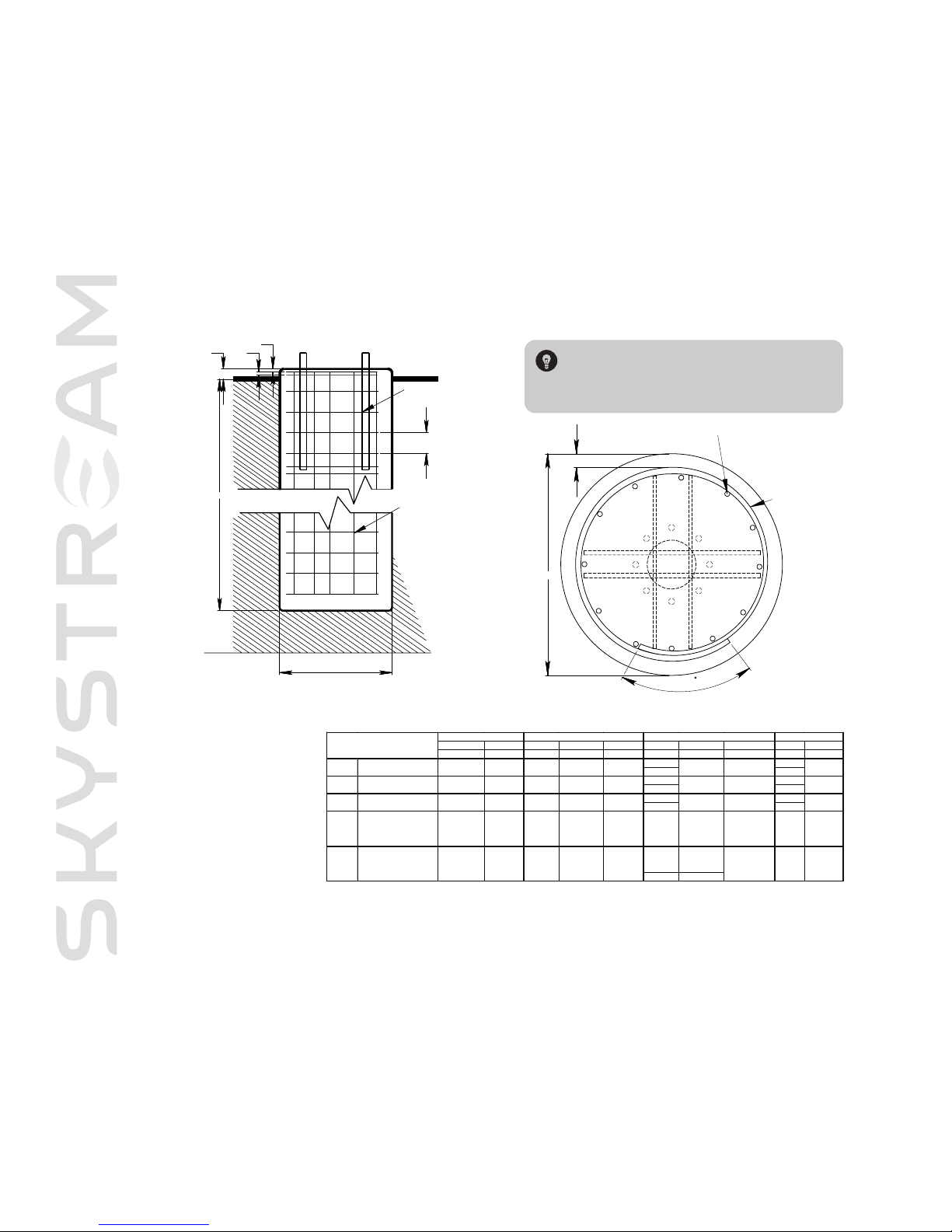
Technical drawings for the pier foundation are presented in
FFiiggss.. BB22 aanndd BB33
.
The pier diameter is 24 inches (61 cm) and the depth of the pier will vary
from 5 to 11 feet (1.5 m to 3.35 m) depending on soil classification. Refer
to
FFiigg.. BB44
(found on pg 4 ) to determine the soil classification.
A typical pier foundation
ä
Page 28
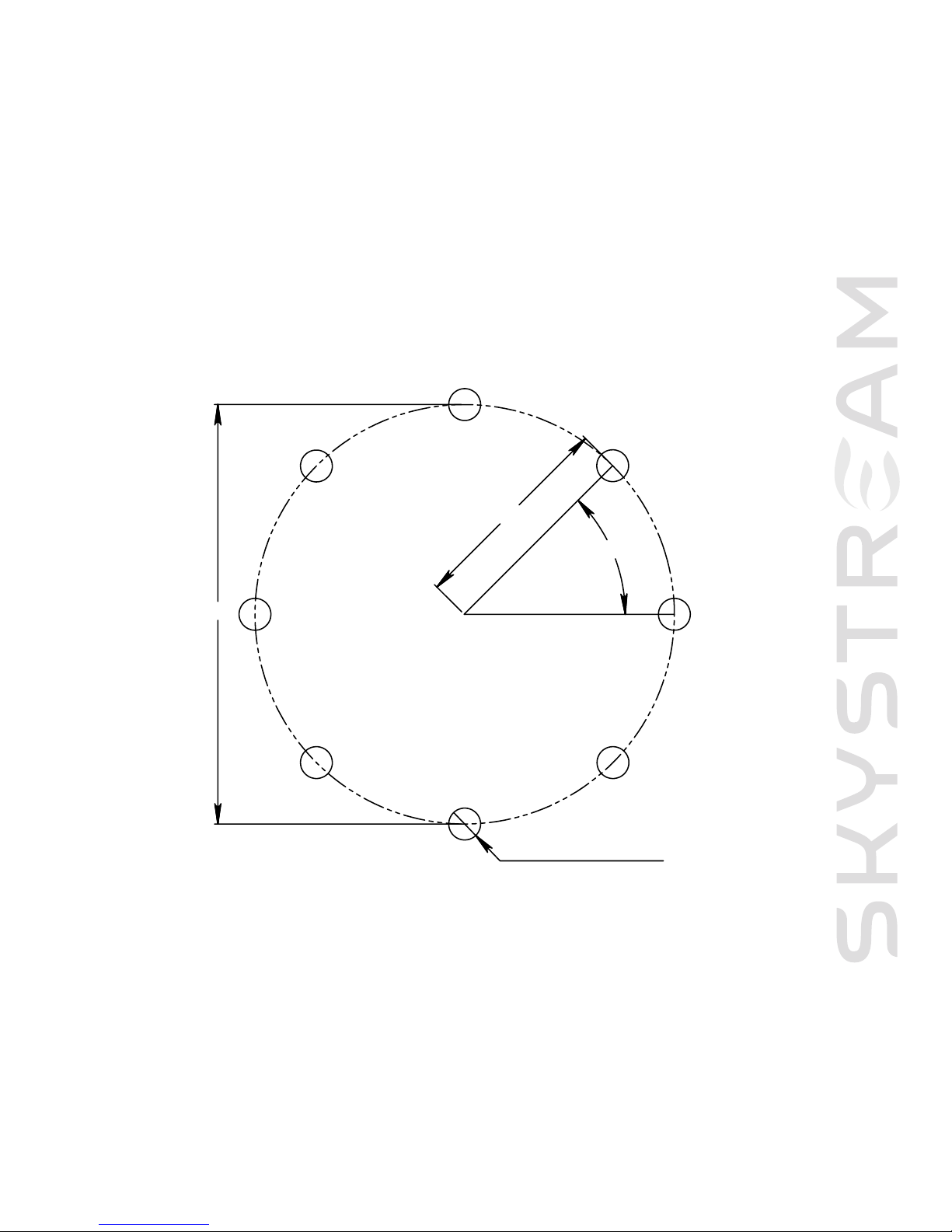
SKYSTREAM 3.7 FOUNDA TION INSTALLA TION GUIDELINES
3
1-1/4" DIA HOLE 8X
45°
8-1/2"
17"
Fig. B1 Bolt template
Page 29
B
B
A
R
O
V
E
RL
A
P
M
I
N 2
9
3" CLR MIN.
T
IES
VERTICAL REINFORCEMENT
SKYSTREAM 3.7 FOUNDA TION INSTALLA TION GUIDELINES
4
Fig.B3 Technical drawing for Pier Foundation
TIP: Because special equipment is required to cut and
bend the reinforcing bar it may be most economical to
contract with a local concrete company to manufacture the
reinforcement structure for the pier foundation.
B
A
9" O.C MAX, TYP.
2
"
2"6"
WATER TABLE
REINFORCEMENT, TYP.
OF FOUMDATION
BELOW BOTOM
VERTICAL
CIRCULAR TIES
GRADE
Lateral Ver tical Shear (V) M om ent (M ) V ertical (P) Depth (A) Diameter (B) Projection (C ) Vertical Ties
psf psf lbs. ft-lbs lbs feet inches inches
6#-)8(6
6#-)21(5
6#-)8(8
6#-)21
(7
6#-)8(01
6#-)21(9
10 30
Soil Clas sific ation
Allowable SoilPres sur e
1200
400
200
150
Class 5
Crystalline be drock
Sedimintary and
foliated rock
Sandygr avel and/or
grave l (GW and GP)
Sand , s it y s and, clayey
sand, sity gr avel and
claye gr avel (SW, SP,
SM, SC , GM and GC)
Clay, sa n d clay, sity
clay, clayey s it, s ilt, and
sandy silt(CL,ML, MH
and CH)
Class 1
Class 2
Class 3
Class 4
100
12,000
4000
3000
2000
1500
Design Loads at Tower Base*
867 26,290 760
867 26,290 760
867 26,290 760
867 26,290 760
867 26,290 760
Minimum Pier Dim ens ions**
10
11
24
24
24
24
24
6
6
6
6
6
Reinforcement
(12)-#6
(12)-#6
#4 @ 9"
O.C. max
#4 @ 9"
O.C. max
#4 @ 9"
O.C. max
#4 @ 9"
O.C. max
#4 @ 9"
O.C. max
***installation of cirv ular ties and anc hor bols shall be in accordance w ith the draw ings.
* These Are the unf actored w ind turbine ex tremeloads us inga hub-height wind s peed of 62.9m/s (140 mph), a w ind shear of 0.20 and a tow er drag coef f icient of
0.28 [ from polhamus, E.C., NASA CR 3809, 1984].
Fig. B2 Technical drawing for Pier Foundation
Fig. B4 Soil chart
Page 30
5
SKYSTREAM 3.7 FOUNDA TION INSTALLA TION GUIDELINES
2-1 Forming and Reinforcing Bar
Position reinforcing bar per
FFiigg.. BB22
. Circular ties require a minimum 29 inch (73.6 cm) overlap and a minimum 3 inch (7.62 cm) clear-
ance from outside diameter edge of pier. Circular ties are #4 reinforcing bar with maximum 9 inch (23 cm) spacing. Vertical reinforce-
ment bars are 12, #6 reinforcing bars equally spaced about circular ties. Forming is most easily accomplished using 24 inch (61 cm)
sonotube. Forms must be removed before backfilling. The sonotube need not extend full depth of foundation if excavation is in solid
undisturbed soil. See Figure B2. Position 4, #6 cap bars as shown in Figure B2.
2-2 “J” Bolts & Template
• Before pouring the foundation the “J” bolts
MMUUSSTT
be
SSEECCUURREELLYY
locked in position.
• A paper template is provided with the bolt kit. Use this template to drill a wood template to hold the “J” bolts in position while
concrete is poured.
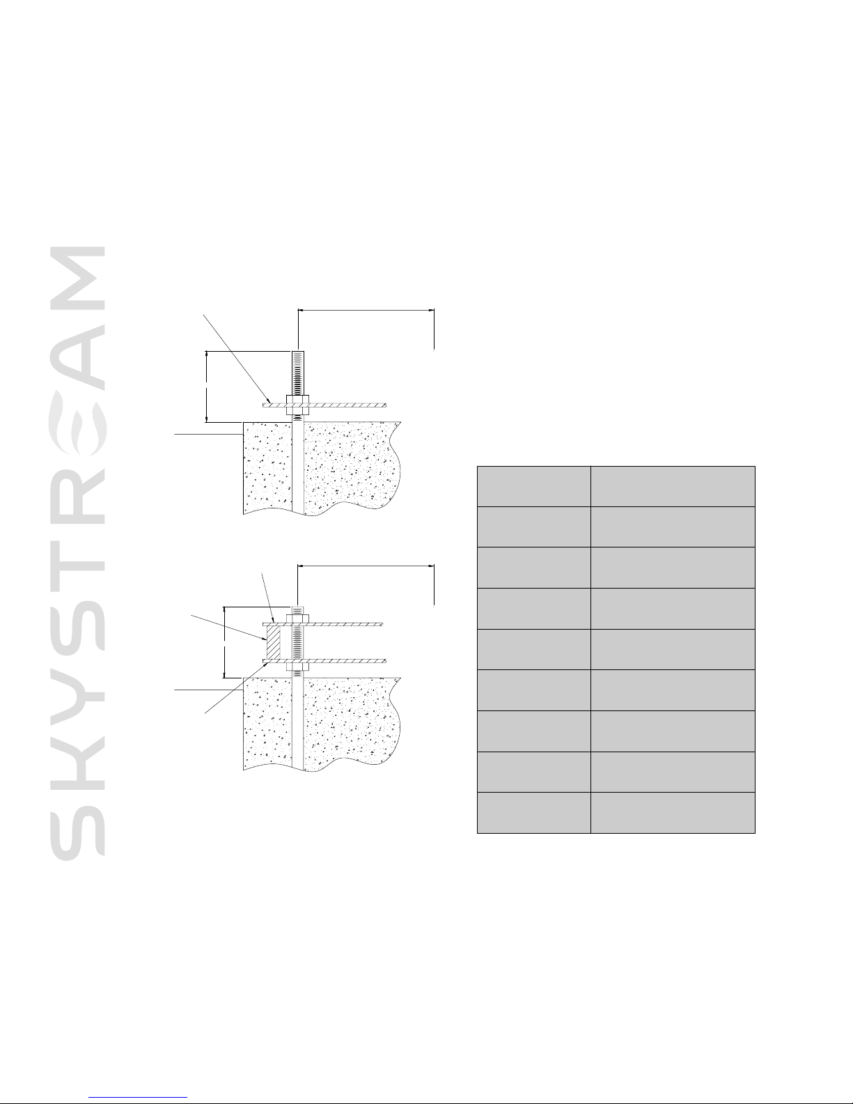
• Two methods of framing the “J” bolts are presented in Figure B4. The first method uses a single template while the second method
utilizes two templates sandwhiched between lengths of 2”x4”lumber. Regardless of the method be sure bolts are correctly posi-
tioned prior to pouring concrete.
• Fabricate a wood template by securing the paper template to the wood template material (3/4” plywood works well).
• Center punch the center position of each “J” bolt. Remove the paper template and drill a 1.25 inch (3.1 cm) mounting hole for each
bolt. If possible compare the template to the tower base to assure bolts will be positioned correctly.
• Mount each of the “J” bolts to the wood template by using a pair of foundation nuts to clamp the template between the nuts.
• Adjust the “J” bolts to extend 7 – 8 inches (17.8 cm-20.3 cm) above foundation as shown in Figure B4.
• Assure all bolts are vertical and parallel to each other.
Note:Take the time to prepare an accurate and strong template to position
and secure the J bolts.This will save much time and difficult rework.
Page 31
6
SKYSTREAM 3.7 FOUNDA TION INSTALLA TION GUIDELINES
1
7" bolt circle
7
"- 8" above foundation
t
emplate
17" bolt circle
7"- 8" above foundation
template
template
2 X 4
Fig. B5 J bolts and template
2-3 Pier Foundation Specifications:
DDiiaammeetteerr
24 inches (61 cm)
DDeepptthh
Depends on soil conditions
Minimum 2500 PSI, 28 day strength,
5% air entrapment
PPiieerr PPrroojjeeccttiioonn
AAbboovvee GGrraaddee
RReeiinnffoorrcciinngg BBaarr
ASTM A615 Grade 60
#4 reinforcing bar,
17-18 inch (43 cm) diameter,
29 inch (73.6 cm) overlap
VVeerrttiiccaall RReeiinnffoorrcceemmeenntt
12 equally spaced #6 reinforcing bar
42 inch (1 m) length,
1.25 inch (3.1 cm) diameter,
6 inch (16.24 cm)
“J”
““JJ”” BBoolltt PPrroojjeeccttiioonn
AAbboovvee FFoouunnddaattiioonn
CCoonnccrreettee
CCiirrccuullaarr TTiieess
AAnncchhoorr ““JJ”” BBoollttss
7-8 inches (17.8 - 20.3 cm)
6 inches (16.24 cm)
Page 32
7
SKYSTREAM 3.7 FOUNDA TION INSTALLA TION GUIDELINES
3-1 Reinforcing Bars
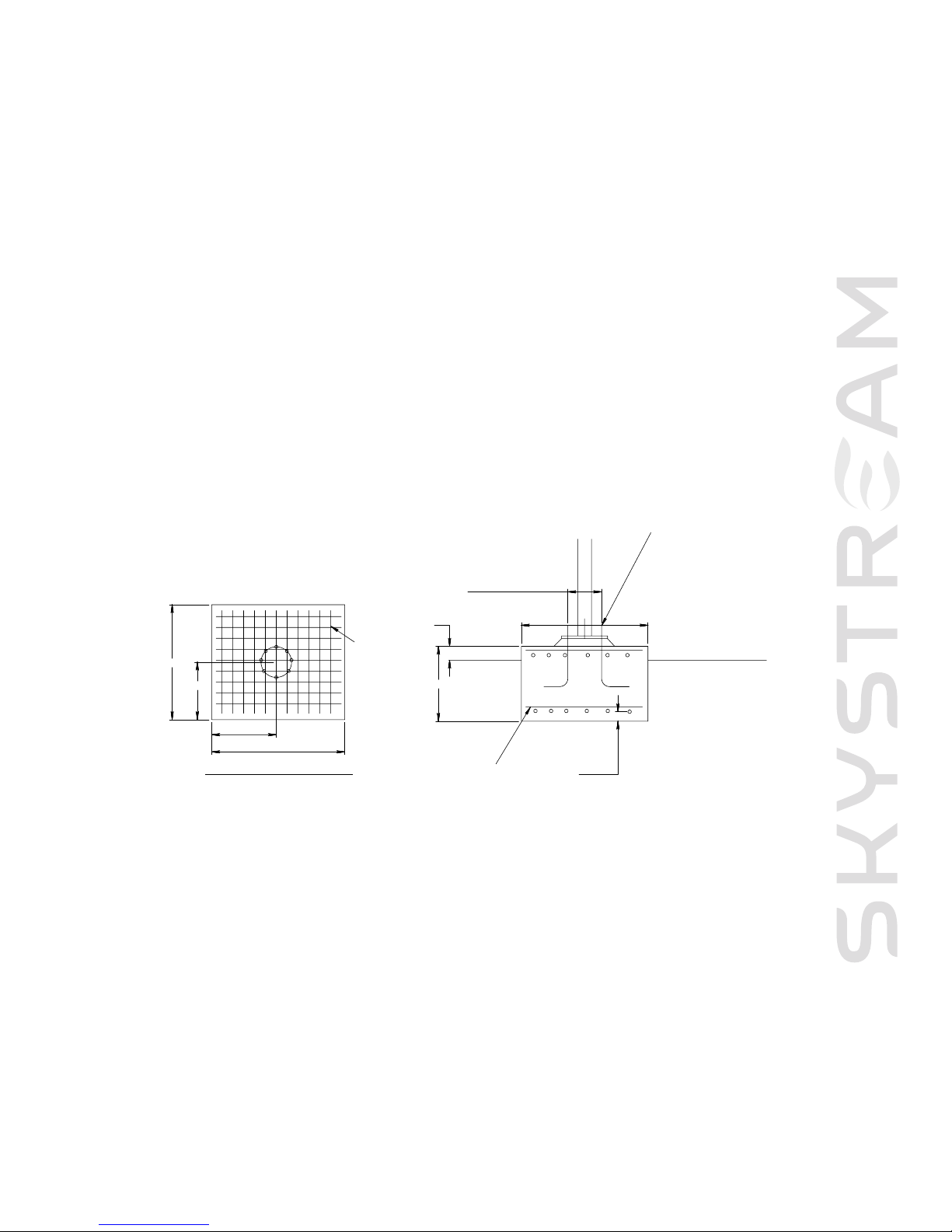
Position reinforcing bar “mats” as indicated in
FFiigg.. BB66
. Reinforcing bar is #6 bar spaced at 8 inch (20.3 cm) intervals. Reinforcing bar mats
positioned with minim
um 3 inch (7.6 cm) concrete co
v
er top and bottom.
Three - MAT Foundation
The MAT foundation is presented in
FFiigg.. BB66
.The foundation is a 6 foot by 6 foot (1.8 m x 1.8 m) square with a depth of 3 feet (.9 m).
The MAT foundation is designed for an allowable vertical bearing pressure of 1,500 PSF (IBC Class 5 Soil per Table 1804.2).
3'-0"
6'-0"
6'-0"6"
3'-0"
3'
17" dia bolt hole circle
top and
bottom
3" cover
6'-0"
top and bottom
1 - 1/4" DIA ANCHOR BOLTS (8 PLACES)
#6 @ 8" both ways
ground elevation
#6 @ 8" both wats,
top and bottom
Mat Foundation Section
G
eneral notes
1) The mat foundation was designed in accordance with the IBC 2003
2
) A professional engineer registered in the state where the project is located shall assume responsibility for
the site – specific design. The P.E. shall shall assure design suitability for varying site and soil condition
such as soil classifications, water table, existence of expansive/collapsible soils, susceptibilityto
liquefaction, frost depth, etc.
3) The mat foundation is for a allowable vertical bearing pressure of 1,500 PSF (IBC class 5 soil per table
1804.2)
4) All foundation elements shall bear on properly prepared soil
5) Soil types and properties shall be verified by the project P.E.
6) Concrete work shall be in conformance with the requirements set forth in ACI 301/318
7
) Anchor bolt design shallbe provided by others. Anchor bolts numbers, size, type, and configuration shall
be capable of resisting all applied moment, shear, and axial forces
8) Concrete shall have min 2,500 PSI 28-day strength and 5% air entrainment +/-1% Concrete unit weight
shall not exceed 150lbs/ft3
9) Reinforcing steel shallbe ASTM A615 grade 60 deformed bars
10)Wind loads per IEC 200x were calculated by others:
Base moment: 26,290 ft-lbs
Base shear: 867 lbs
Axial load: 760 lbs
Fig. B6 Technical drawings for Mat Foundation
Page 33
8
SKYSTREAM 3.7 FOUNDA TION INSTALLA TION GUIDELINES
3-2 “J” Bolts and Template
• Before pouring the foundation the “J” bolts
MMUUSSTT
be
SSEECCUURREELLYY
locked in position.
• A paper template is provided with the bolt kit. Use this template to drill a wood template to hold the “J” bolts in position while
concrete is poured.
• Two methods of framing the “J” bolts are presented in Figure B4. The first method uses a single template while the second method
utilizes two templates sandwhiched between 2”x4” lenghts of lumber. Regardless of the method be sure bolts are correctly posi-
tioned prior to pouring concrete.
• Fabricate a wood template by securing the paper template to the wood template material.
• Center punch the center position of each “J” bolt. Remove the paper template and drill a 1.25 inch (3.1 cm) mounting hole for each
bolt. If possible compare the template to the tower base to assure bolts will be positioned correctly.
• Mount each of the “J” bolts to the wood template by using a pair of foundation nuts to clamp the template between the nuts.
• Adjust the “J” bolts to extend 7 – 8 inches (17.8 cm-20.3 cm) above foundation as shown in Figure B5.
• Assure all bolts are vertical and parallel to each other.
3-3 MAT Foundation Specifications
DDiimmeennssiioonnss
6 feet x 6 feet x 3 feet (1.8 x 1.8 x .9 m) deep
RReeiinnffoorrcciinngg BBaarr
ASTM A615 Grade 60
AAnncchhoorr ““JJ”” BBoollttss
32 inch (81.3 cm) length, 1.25 (3.1 cm) diameter, 6 inch (16.24 cm) “J”
CCoonnccrreettee
Minimum 2500 PSI, 28 day strength, 5% Air Entrapment
Note:Take the time to prepare an accurate and strong template to position
and secure the J bolts.This will save much time and difficult rework.
Page 34
9
SKYSTREAM 3.7 FOUNDA TION INSTALLA TION GUIDELINES
Four - Electrical Conduit
Electrical conduit may be cast into the foundation such that the
conduit continues below grade to electrical panel. Alternately
wire may be routed between tower base plate and foundation.
Refer to local building codes
BBEEFFOORREE
pouring concrete.
Building codes typically require direct burial cables be buried to a
minimum depth of 24 inches (61 cm) while cables in conduit may
be buried at a depth of 18 inches (46 cm). Additionally, most
codes prohibit embedding cables directly in concrete. Refer to
local codes for conduit size and minimum depth requirements.
Note: Space between
foundation and bottom
of tower base plate should
be filled with high strength
non-shrink grout after final
positioning of tower on
foundation.
Page 35

Tower Installation Instructions
Southw
est Windpower, Inc.
1801 West Route 66 - Flagstaff, Arizona 86001
Phone: 928.779.9463 - Fax: 928.779.1485
Web: www.skystreamenergy.com
October 2006 Southwest Windpower, Inc. All Rights Reserved
Appendix C
Page 36

SKYSTREAM 3.7 APPENDIX C: TO WER INSTALLA TION
Skystream 3.7 Owner’s Manual
Appendix C: Skystream Tower Installation Instructions
Important Safety Instructions _______________________________ 1
1) INTRODUCTION __________________________________ 2
1-1
Required Tools & Equipment ______________________ 2
2) SET UP & PREPARATION__________________________ 3-5
3) RAISING THE TOWER ____________________________ 6
4) LOWERING THE TOWER __________________________ 7
5) LEVELING THE TOWER __________________________ 8
6) GIN POLE INSTRUCTION SHEET ________________ 9
6-1
Package Contents______________________________ 9
6-2
Preparations ________________________________ 9
Page 37
SKYSTREAM 3.7 APPENDIX C: TO WER INSTALLA TION
1
IMPORTANT SAFETY INSTRUCTIONS
READ THESE INSTRUCTIONS IN THEIR ENTIRETY BEFORE INSTALLING.
1) SAVE THESE INSTRUCTIONS. This manual contains impor tant instructions
for raising, lowering and leveling the tower that must be followed.
2) Read these instructions in their entirety before beginning the installation.
3) Be extremely careful of overhead power lines.
4) Do not start installation unless all required equipment and tools are on site.
5) Foundation concrete must be completely cured. (Minimum 2500 PSI, 28 day
strength)
6) Install tower in accordance with local zoning and building codes. Obtain all
necessary building permits PRIOR to installation.
7) Remain at a safe distance when raising and lowering the tower. Do not walk
or stand under the tower and keep clear of cables.
Professional installation
highly recommended
TIP: Helpful information
to ease the installation
Warning: Risk of injury or
death - proceed with extreme
caution
Professional installation
highly recommended
In this guide
Page 38

SKYSTREAM 3.7 APPENDIX C: TO WER INSTALLA TION
2
One - Introduction
These instructions require use of Southwest Windpower’s Hinge and Gin Pole Kits, which were specifically designed for this application.
Additionally, these instructions assume a bolt kit was purchased and the correct foundation nuts, bolts and washers are available.
Once the tower is raised into position the hinge and gin pole are removed. It is therefore not necessary to purchase these items. Should
it be necessary to lower the tower, the hinge and gin pole may be reinstalled and used to lower and raise the tower.
1-1 Required Tools & Equipment
The following tools and equipment are necessary to install the tower:
• Hinge Mounting Kit - Part Number 3-CMBP-3063
• Gin Pole Kit - Part Number 3-CMBP-3054
• 16 Flat Washers, 1 1/4” ID, galvanized SATM F436, (SWWP part number 3-HDWA-917)
• 19 Nuts, 1 1/4”, galvanized, (SWWP par t number 3-HDNT-908)
• Bubble level, (easier with two levels)
• Pair of 2” open end wrenches.
• Pair of adjustable wrenches to install hinge plates and gin pole, tape measure.
Page 39
SKYSTREAM 3.7 APPENDIX C: TO WER INSTALLA TION
3
Two - Set Up & Preparation
Carefully read and perform the following steps to prepare for raising the tower.
• Determine the three foundation bolts to be used to mount the hinge.The hinge
is installed in the direction the tower will be “tilted down”. Refer to Fig. 2C.
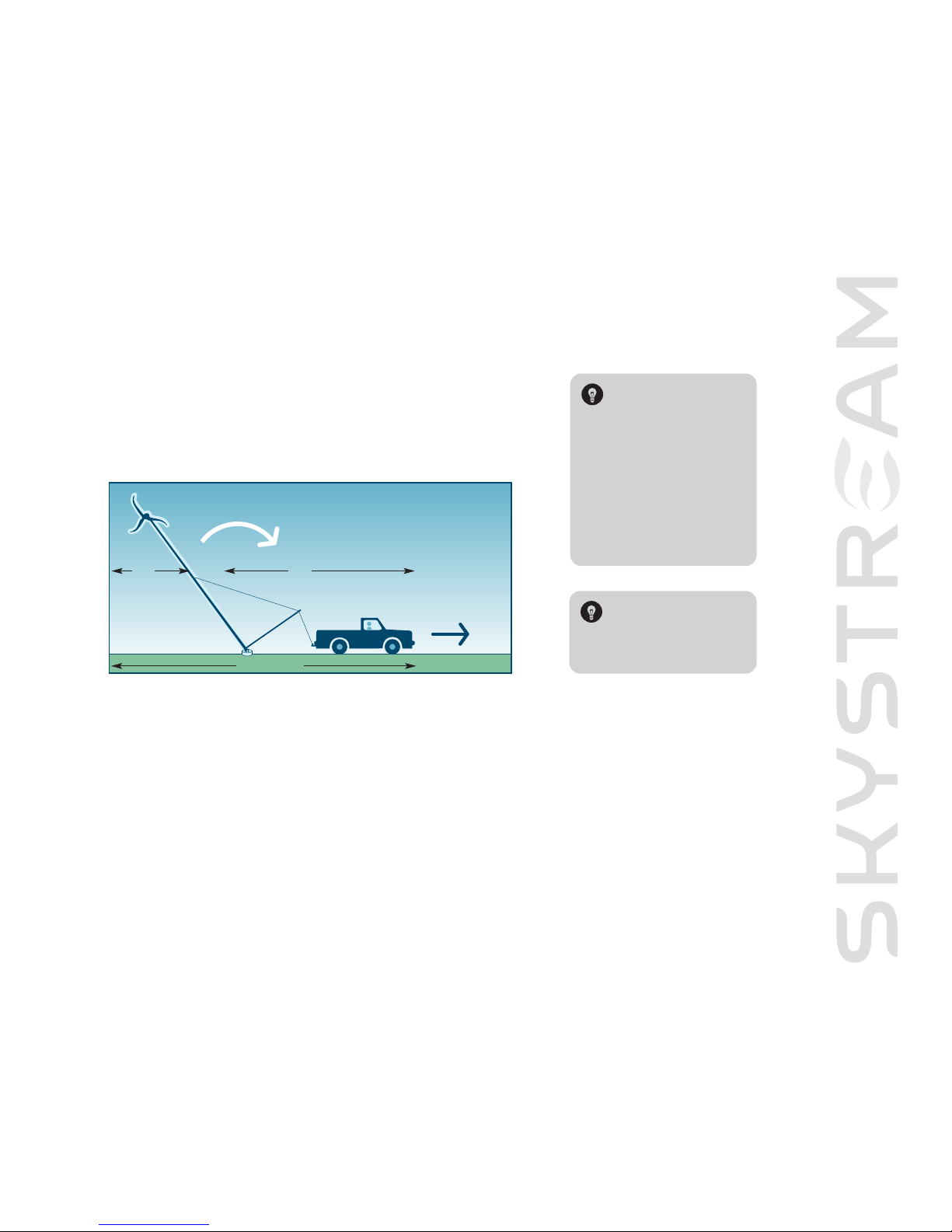
TIP: Approximately 90 feet
(43 meters) are required
to raise the tower vertically
into position. Forty feet
(19 meters) are required on
one side of the foundation
for the tower and wind
generator. An additional
50 feet (24 meters) are
required on the other side
of the foundation for the
gin pole and pulling vehicle.
See Illustration I.
• Screw a 1 1/4” nut on each of the three foundation bolts that will be used to mount the tower hinge. Thread the nuts down so the
top of the nut is approximately 5” (13 cm) from the top of the foundation bolt. Refer to Fig. 1C.
• Screw a 1 1/4” nut on each of the eight foundation bolts.The foundation bolts used to mount the hinge will have two nuts. Leave a
gap of approximately 7/8” (2 cm) between the nuts to accommodate the hinge.
• Bolt the hinge to the tower base plate using the 7/8”x 51/2” bolts and nuts supplied with the hinge kit. Fully screw the nuts onto
the bolts.The bolts act as hinge pins, therefore, it is not necessary to overly tighten the nuts on the bolts.
• Using suitable lifting equipment, lift the tower base (with hinge) and position the hinge slots between the nuts and the foundation
bolts. Refer to Fig. 1B in Appendix B.
TIP: The 5 adjustment is
temporary. The height of
the hinge must be adjusted
as described in latter
instructions.
Fig. 1C
90’ (43 m)
40’
(19 m)
50’
(24 m)
Page 40
SKYSTREAM 3.7 APPENDIX C: TO WER INSTALLA TION
4
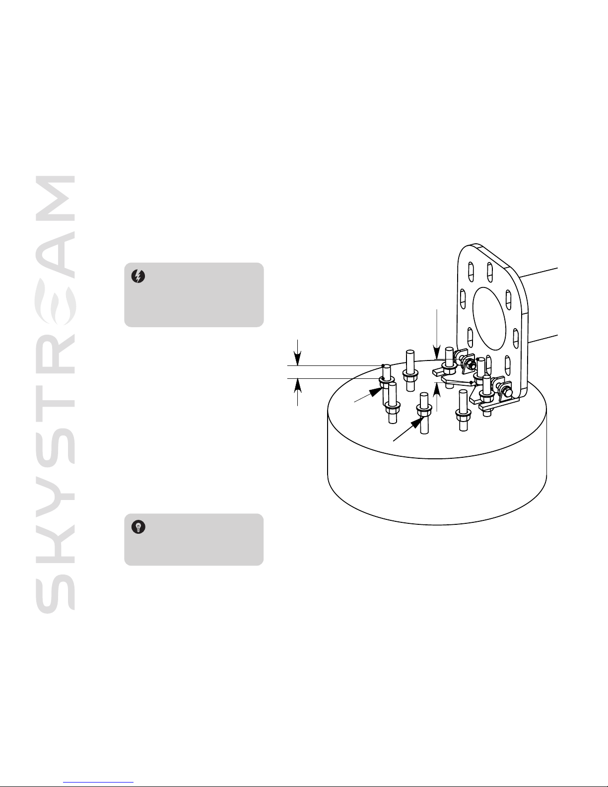
• Tighten the hinge plate nuts such that
the top of the hinge plate is 4 1/4” (10.8
cm) from the top of the foundation
bolts.
• Adjust the remaining nuts as shown in
Figure 2C. The “A” and “B” nuts should
be adjusted such that 2 1/4” (5.7 cm) of
the bolt extends above the washer. The
remaining three nuts should be adjusted
lower than the “A” and “B” nuts. These
nuts will be tightened after leveling the
tower.
• Adjust the remaining nuts as shown in
Figure 2C. The “A” and “B” nuts should
be adjusted to be level with nuts securing the hinge.The remaining three nuts
should be adjusted to a lower level than
the “A” and “B” nuts.These nuts will be
tightened after leveling the tower.
Fig.
2C Hinge assembl
y and n
ut placement.
4.25” (10.8cm)
from top of hinge
plate to top on
anchor bolt
2.25” (5.7cm) from
top of washer A and
B to top of anchor
bolt
TIP: Install the gin pole bolts
from above to ease removal
when the tower is raised into
position
.
WARNING: The 4 1/4” height
adjustment is VERY important to
insure the foundation bolts will clear
the slotted holes in the base plate
allowing the tower to fully tilt into
position.
A
B
Page 41
SKYSTREAM 3.7 APPENDIX C: TO WER INSTALLA TION
cable
eye
M16 bolt
and nut
5
• Using an M16 nut and bolt install one of the gin pole cables on the lever arm of
the gin pole. Using a shackle supplied with the gin pole secure the opposite end
of the cable to the tower. Refer to the Figures A and B below.
• Install the second gin pole cable to the weldment on the gin pole using the
shackle provided.
• Securely connect the other end of the cable to the vehicle to be used to raise
the tower.
Fig. 3C cable-gin pole assembly details Fig. 4C cable-tower assembly details
TIP: The tower is now set to be
raised. Southwest Windpower recommends raising the tower once without
the wind turbine installed.This permits
checking the proper operation and
installation of the hinge and gin pole
and also allows inexperienced installers
an opportunity to practice raising the
tower without risking damage to the
wind turbine.
Page 42

SKYSTREAM 3.7 APPENDIX C: TO WER INSTALLA TION
6
Three - Raising the Tower
Refer to your Skystream Owner’s Manual for directions on mounting Skystream on the tower. If you have not raised a tower before it is
also recommended to first raise the tower without the turbine. Raising the tower without the turbine provides the opportunity to practice the procedure without risking damage to the turbine.
A minimum of three people are required to raise the tower.
• Position the remainder of tower mounting hardware and tools close to the tower foundation.
• Securely connect the gin pole cable to the raising vehicle.
• Very slowly, drive the vehicle away from the tower taking the “slack” out of the cable. Keep the vehicle inline with the tower while
slowly raising the tower.
WARNING: Use extreme caution when raising the
tower. Keep well away and to sides of tower and
cable. Beware of overhead power lines.
• As the tower approaches vertical it will reach a “balance point”.At this point two people can take over from the vehicle and use
the gin pole to manually “lower” the tower into the full upright position. The goal is to prevent the tower from “falling” into the final
vertical position after it passes the “balance point”.
• With the tower fully vertical and supported on the foundation bolts, install remaining washers and hand tighten remaining nuts.
• If the tower was raised without the wind turbine, refer to the Lowering the Tower section and follow the instructions. If the tower
was raised with the wind turbine proceed to Leveling the Tower section.
Page 43
SKYSTREAM 3.7 APPENDIX C: TO WER INSTALLA TION
7
WARNING: Use extreme caution
when lowering the tower. Keep well
away and to sides of tower and cable.
WARNING: Someone MUST be in the vehicle
at all times to control lowering the tower. The
“pulling” force the tower exerts greatly increases
as the tower approaches the horizontal. In other
words the tower is lowered using the vehicle
brakes to slow the descent of the tower. During
lowering keep the vehicle engine running to
provide power brake assistance.
Four - Lowering the Tower
Lowering the tower is essentially the reverse of raising the tower.The same precautions should be observed, including positioning the hinge so the tower base
plate clears the foundation bolts. As with raising the tower a minimum of three
people are recommended.
• Position suitable bracing support the top of the tower after it is lowered.The support should be located approximately 8 feet
(2.5 m) from the top of the tower to clear the turbine blades.
• If not already in place, install the hinge plate by sliding the hinge between the lower and middle nuts on the foundation bolts.
Slide the 7/8” diameter bolts that act as hinge pins through the hinge and tower foundation plate and snuggly tighten the 7/8”
nuts.
• Securely tighten the 1 1/4” nuts that secure the hinge to the foundation bolts. Check the distance from the top of the hinge to
the top of the foundation bolts is 4 1/4”. Adjust if necessary. Refer to Fig. 2C.
• Bolt the gin pole to the foundation plate and connect the cable from gin pole to the weldment on the tower.
• Connect the second cable to the gin pole and lowering vehicle.
• Position the vehicle so it is in line with the tower and there is approximately 1 foot (30 cm) of slack in the gin pole cable.
• Remove the remaining 1 1/4” nuts and washers from the foundation bolts.
• The lowering process is star ted by two people lifting the gin pole so that the tower starts to tilt and takes up the cable slack.
• Once the tower passes the balance point the the vehicle can then be used to fully lower the tower.
Page 44

SKYSTREAM 3.7 APPENDIX C: TO WER INSTALLA TION
8
Five - Leveling the Tower
Leveling the tower is most easily accomplished using only four of the eight foundation bolts. Once the tower is leveled the remaining
bolts can be fully tightened to secure the tower.
Be aware that leveling the tower may require some trial and error adjustments – even though the base is level, the upper tower flange
may be off level due to manufacturing tolerances.
To level the tower:
• Level the tower on a calm day to minimize movement of Skystream. Star t by loosening all the upper foundation nuts about a full
turn.
• Loosen and lower the four nuts on the “sides” of the foundation base plate. In other words the tower should be suppor ted by the
four “corner” nuts of the tower base plate. (refer to Fig. 2C, Bolts A and B are “corner” bolts)
• Using two bubble levels set perpendicular to each other on the base plate adjust the foundation nuts until the tower is level.
Magnetic bubble levels may make this process easier.
• Once the tower is level tighten all nuts and recheck level.
Observe the position of Skystream on calm days. If the wind turbine seems to favor a single position with no wind, the tower may
require fine tuning even if it appears level using the bubble leveling technique.
To fine tune the tower realize that the nose cone of the wind turbine will “point” in the direction of the tower low side.Therefore, to
level the tower, slightly raise the side of the tower under the nose cone or lower the side of the tower opposite the nose cone. Make
fine adjustments. Approximately one turn of a foundation nut equates to slightly more than 1/8” (6.4 mm) so even a half turn adjustment will make a difference.
Page 45

SKYSTREAM 3.7 APPENDIX C: TO WER INSTALLA TION
9
Six - Gin Pole instruction Sheet
6-1 Package Contents
Before you begin, inspect the contents to make sure there is no damage or missing par ts.
l
Gin Pole Kit (includes):
- gin pole
- two aircraft cables
- two shackle
- two M16 (metric 16 mm) bolts
6-2 Preparations
Instructions to prepare the gin pole to lift the tower. This is to be done when you have correctly located the tower with respect
to the foundation and have secured the tower to the hinge plate.
• Pass the eye of the cable through the slot, pass the M16 through the eye and screw the M16 nut on the bolt. Repeat for
the second cable. See Fig. 3C on page 5.
• Slip the bottom of the gin pole over the bottom flange of the tower as shown in Fig. B on page 39.
• Secure the gin pole to the tower with the three M24 bolt and nuts
• The two cables will now be hanging down the gin pole
• Secure the cable on the side of the tower to the hinge tab midway down the tower with the
shackle provided.You may have to pull slightly to ensure tension.
• Secure the other cable to your car or truck with the other shackle provided.
• You are now ready to lift the turbine-tower assembly. Fig. 5C shown here
demonstrates your assembled gin pole.
- two M16 nuts
- three M24 (metric 24 mm) bolts
- three M24 nuts
Fig. 5C Assemmbled Gin Pole
 Loading...