


Skyshark R/C
FANTASY
The Skyshark Fantasy was designed for both
beginning low wing pilots and serious sport flyers. It’s excellent slow flight abilities and gentle
stalls make the Fantasy one of the best low wing
trainer kits available today. Heavy duty wing
spars and fuselage make for an aircraft that can
withstand the mishaps that normally occur with a
begining pilot. Laser cutting and hand selected
balsa allows us to keep the weight and building
Wingspan . . . . . . . . . . . . . . . . . 60 inches
Wing Area . . . . . . . . . . . . . . . . 593 sq. inches
Overall Length . . . . . . . . . . . . . 52 inches
Flying Weight . . . . . . . . . . . . . . 5.5 - 6.5 lbs
Engine . . . . . . . . . . . . . . . . . . . .45 - .61 2-stroke
.56 - .91 4-stroke
Radio . . . . . . . . . . . . . . . . . . . . 4 Channel Min.
Building Experience Required . . .Basic
Flying Experience Required . . . Trainer
Average Build Time . . . . . . . . . . 30 hours
time to a minimum. If you are an experienced
builder, the Fantasy can be built and ready to fly
in the same amount of time as many ARFs. For
the sport flyer, the Fantasy features, a larger
rudder for better aerobatics, swept wing design
for speed and a simple, no hassle, engine
mounting setup. Engine choices also vary from a
simple .46 to a high perfomance .61. You can
even add a tuned pipe for real excitement!
Skyshark R/C Corporation
75 Mid Cape Ter, Ste 7
Cape Coral, FL 33991
Phone: (239) 800-1941
Website: www.skysharkrc.com
email: custserv@skysharkrc.com

Thank you for purchasing the Fantasy from Skyshark R/C.
Our goal, through computer technology and state-of-theart production techniques, is to offer aircraft that are fast
and easy to assemble with minimal sanding and shaping.
tle as 20 - 30 hours.
Occasionally hints will be included at certain building
steps. These are not required for completion, rather they
are tips intended to ease a particular process.
Your airplane has many unique features in its
design:
CAD Design
CAD design allows strength to be built into the airplane
without sacrificing weight. Accurate parts design and
placement ensures a perfect fit.
CAD Drawn Plans
The plans in this kit are not copied from a master set! They
are originals drawn directly from the CAD program where
the airplane was designed. We do this because it allows us
to use color, which helps you better visualize the various
components of the airplane, and we can use better quality
paper, which greatly reduces the possibility of shrinkage.
Since you’re going to build directly on the plans, they
ought to be the proper size! Also, parts placement is guaranteed to be accurate, so you can build a better, straighter
model.
Laser Cut Parts
The same program that generates the design and plans
also drives the laser, so every part is reproduced exactly as
it was designed. Laser cutting also allows us to fit more
parts on each sheet of wood, reducing the waste, and lowering the cost to you. Since laser cutting does not have the
same limitations that mechanical cutters do, small and
hard-to-produce parts are simply a computer file away, so
you get a more accurate airplane.
The laser does not cut through the wood, it burns its way
through. As a result of this, occasionally there will be
scorching on the surface of the wood. This is normal, and
is only a surface discoloration, and does not affect the
wood in any other way. Similarly, the laser settings are optimized for wood density averages, so occasionally, due to
variations even in individual sheets, some areas might not
cut through completely. This is apparent mainly with the
plywood. Simply use care in removing the parts from the
sheets; most of the time, the parts will literally fall out of the
sheets!
Some hardware including a motor mount is not included in
the kit. There are so many choices for quality hardware that
these choices are left to the individual preferences of the
builder, rather than include something in the kit that you’ll
probably throw away anyway.
Decals
The decals provided are made from fuel-proof vinyl so
there is no need to clearcoat them. To apply, clean the surface with alcohol and wipe dry. Put a drop or two of soap
in a spray bottle filled with water. Shake the mixture and
spray onto the surface that you will be applying the decal
to. Peel the backing from the decal and apply to the surface
without pressing.Using a credit card or other flat item rub
the decals onto the surface from the center moving out to
the edges. This will force any water from under the decal.
Wipe with a clean dry cloth and remove the masking from
the decal. If the decal lifts while removing the masking,
allow the decal to dry before attempting to remove the
masking.
Engine Options
Engine choices range from .46 to .61 2-strokes, or .56 to
.91 4-strokes. The firewall is a limited size so make sure
you check you engine mount fit before deciding on a larger engine.
Retract Options
Retract installation is left up to the builder.
Dual Aileron Servos
Dual servos can be added to the wing instead of a single
servo torque rod setup without affecting performance. We
also leave this up to the builder
General Building Information
The Fantasy can be assembled by a person with little or no
building experience. This manual is written for the beginning builder. An advanced builder can build this kit in as lit-
This aircraft is not a toy. It must be flown in a responsible
manner according to the rules set forth by the Academy of
Model Aeronautics. The builder assumes the responsibility
for the proper assembly and operation of this product.
Skyshark R/C shall have no liability whatsoever, implied or
expressed, arising out of the intentional or unintentional
neglect, consequential damage, misuse, abuse, or abnormal usage of this product. Skyshark R/C shall have no liability whatsoever arising from the improper or wrongful
assembly of the product nor shall it have any liability due to
the improper or wrongful use of the assembled product.
Skyshark R/C shall have no liability for any and all additions, alterations, and modifications of this product.
Having said that mouthful, turn the page and start building
the best sport plane on the market!
2

Kit contents:
Needed to complete kit:
Fuselage Side Plan Sheet
Wing Plan Sheet
Laser Cut Wood Pack
1/4” x 3” x 24” Balsa (1)
3/32” x 4” x 36” Sheeting (5)
3/32” x 4” x 24” Sheeting (3)
1/4” sq. x 36” Balsa Sticks (4)
3/16” sq. x 24” Balsa Sticks (5)
1/4” x 1” x 36” Leading Edge (2)
3/8” x 1/2” Wing Spars (4)
3/8” x 1” x 36” T.E. and Aileron Stock (2)
5/8” x 1” x 5-7/8” Balsa (2)
Clear Canopy
Main Landing Gear
Dubro Nose Wheel Gear
Nose Wheel Gear Horn w/5/32” Collar
2-3/4” Dubro Wheels (3)
Dubro Aileron Torque Rods (2)
Sullivan Gold-N-Rods 36” (2)
Sullivan Gold-N-Rods 12” (2)
Sullivan Clevis Adapters (4)
Sullivan Clevises (4)
2-56 Pushrods (4)
Landing Gear Blocks (2)
Gear Anchor Blocks (2)
Wing Mounting Blocks (2)
F-1 Firewall
1/4” Wing Dowel
2 oz. Fiberglass Wing Joining Material
Elevator Connector Wire
Landing Gear Straps (4)
5/32” Wheel Collars (4)
CA Hinges (18)
Dubro Control Horns (1 pk.)
Dubro Easy Connectors (2)
1/4” Nylon Wing Mounting Bolts (2)
Thin CA Glue
Medium CA Glue
Thick CA Glue
(We use Balsa USA Gold on our prototypes)
RC56 Canopy Glue
5 Minute Epoxy
30 Minute Epoxy
Epoxy Brushes
2 rolls of film or fabric covering 72” x 26” each
8 -14 oz fuel tank (Du-Bro)
Silicon fuel tubing
Engine Mount (with nose wheel attachment)
(We recommend Hayes)
Engine and Mounting Hardware
4 Standard Servos
(Cutouts are sized for Hitec)
4 Channel Radio
Battery
6” Servo Extension
2-1/2” Spinner
Propeller
80, 120 and 240 grit sandpaper
Sanding block or bar
1/4-20 Tap & Drill Set
Balsa Filler
Masking Tape
Taildragger Version Only:
Tail gear
1” Tail wheel
3

Occasionally we will make reference to the plan in order to clarify the instructions. We have letters down the side and numbers across the bottom of the plans. In brackets [ ] we will give you the coordinates like a road map to locate the item
referred to. Find the letter and number and where they cross will be the location to look.
When working over the plan, waxed paper should be used to protect the plan and eliminate other frustrations caused by
parts sticking to the paper and the additional sanding involved.
If you plan on building the Taildragger version, please follow the taildragger add-ons listed under the appropriate sections.
Our prototype Tri-gear version required 4 oz. of tail weight with the battery moved to the back of the fuselage servo
tray. The plane was setup with a .46 engine and standard muffler. Be sure to account for this when building. The
Taildragger version should not require any additional tail weight.
Tail Surfaces
1. Find vertical fin (MS401, MS404), elevators
(MS403), horizontal stab (MS405) and rudder (MS402) parts.
2. Over the plans, join MS405 to the 1/4” x 3”
x 24” balsa sheet with thin or medium CA.
4. Remove above pieces from the plan and
mark a center line on the leading edge of
both elevators (MS403) and rudder
(MS402). Do the same on the trailing edge
of the fin and stab assembly.
5. Place a mark on these center lines indicating where the hinges and elevator joiner
wire are to be located. See plan [B24 &P24].
6. With a 3/32” drill bit, drill a hole in each elevator (MS403) half approximately 3/4” deep
to accept the elevator joiner rod. Cut a
groove from these holes on the front edge to
the inner end of each elevator half to allow
the joiner rod to fit flush with the elevators.
Put a few drops of thin CA in the drilled hole
and re-drill with the 3/32” bit once dry. This
will strengthen the hole.
3. Join MS401 to MS404 so they align with
the plans. Use thin or medium CA.
4

7. Where you have marked for the hinge locations on all tail group pieces, carefully cut
hinge slots with a #11 blade.
8. Bevel the front only of two MS403 [J24] and
MS402 [O24].
9. To provide clearance for the elevator joiner
wire, cut a 1/4” half round in the leading
edge of MS402. See photo.
10. Pin two MS403 down on the plan and trial
fit the elevator joiner wire. It should slip in
easily. Apply 5 minute epoxy to the joiner
holes and groove and slide the joiner wire
in place. Let cure and remove from board.
11. Trial fit all hinges to assure proper alignment. Do no glue hinges at this time.
12. Bevel leading dege of all control surfaces
so they move at the proper deflections.
Sand to marked line and round all outside
edges of the tail group. Do not sand areas
that will be inside the fuse and rudder tail
blocks.
Wing Assembly
13. Start the wing assembly by removing the
balsa ribs and 1/8” ply doublers (3 & 4)
from the laser sheets.
Taildragger Only:
Use ply doublers 3T and 4T
14. Glue the appropriate ply doublers to both
sides of R3 and R4. Align these carefully
as these set the angle of and re-enforce
your landing gear
5

15. The wing is sheeted from the leading edge
to the middle of the spar. These sheets
should be made up now while your work
area is clear. Locate (4) 3/32” x 4” x 36”
Balsa sheets and cut them to 30”. With
sand paper or 36” steel rule and a hobby
knife, true on 30” long edge of each sheet.
Over waxed paper, lay 2 sheets, trued
edges together and adjust until there is no
gap between the sheets. When you have a
good match, pin them down. Wick thin CA
along the joint. Unpin when dry and join
the other 2 sheets the same way. Lightly
block sand both sides of the joined sheets
in order to smooth out the glue line.
16. Take the two 8” wide sheets from previous
step and trim each sheet to 5-3/4” wide.
Make a mark 1-3/4” down from the upper
left corner and 1-3/4” up from the bottom
right corner. With a 36” steel rule, carefully
join the two marks and cut along the line.
Set these sheets aside for use later.
17. Start with the right panel. Align and pin the
3/8” x 1/2” x 36” main spar over the plan.
18. Locate two R1 ribs and glue on R1A balsa
wing dowel block on the outboard side of
each R1 rib as shown on the plan. Make
sure you have a right and left.
6

19. Using thin CA, reinforce the thin area of the
tabs on the front of ribs R10 and R11. This
will insure the tabs will stay on the ribs
while you are building the wing.
20. Lay R1 thru R11 over the spar in their proper location on the plan. Place the 1/4” sq.
trailing edge stick against the back of the
ribs in the slot provided. Starting with R1
and working thru R11, lay a small triangle
next to the rib to stand them 90 degrees to
the building surface and verify proper location over the plan. When satisfied, glue to
the main spar and trailing edge with CA.
Be sure to glue only the back of the ribs to
the 1/4” trailing edge. the tab will be
removed later.
Note: An easy way to insure the ribs are aligned
and evenly spaces is to check them with SW1
thru SW10 shear webs. DO NOT glue the shear
webs at this time.
21. Carefully fit the top spar into all rib slots
and glue. Make sure that all ribs remain at
90 degrees from the building surface.
22. Place the 1/4” x 1” x 36” leading edge
piece in the slots provide on the front of
each rib and glue. Glue the leading edge to
the front of each rib only. The tabs will be
broken off and discarded later.
7

23. Locate and glue shear webs SW1 thru
SW10 in place on the rear of the main spar
as show on the plan. Sand the shear webs
as needed to fit. Insure that the grain is
running vertical.
24. Break off the rear tab that holds the 1/4” sq.
trailing edge piece and sand the trailing
edge to match the taper of the ribs. Make
sure to leave the bottom part of the tab
attached to rib. This sets the correct
washout for the wing.
25. Using thick CA glue a 3/32” x 1” x 30”
sheet to the trailing edge of the wing flush
with the 1/4” sq. trailing edge.
26. Locate grooved landing gear blocks (1/2” x
7/8” x 3-7/8”) and drill a 5/32” hole at 90
degrees in the bottom of the landing gear
block groove 3/8” from the end.
8

27. Fit the grooved landing gear block into the
notches in R3 and R4. It should have a 1/2”
overhang on the end with the hole. Insure
this block fits flush with the top edge of the
ribs. When satisfied, remove block and use
30 minute epoxy to glue in place along with
the 1/2” x 7/8” x 1” vertical gear block as
shown in photo.
Taildragger Version:
The gear blocks will be forward of the main
spar.
28. Using the 3/32” tapered leading edge
sheets made previously in step 15, bevel
the angle to match where the ribs meet the
leading edge. Check for proper fit - there
should be no gaps between the sheeting
and the leading edge. Sand if necessary.
31. Using the 3/32” x 4” x 24” sheet provided,
cut two pieces 9-1/2” long. Glue these in
place over R1 thru R4, keeping one end
flush with R1. Cut and fit a piece to fill into
the gap left between the center section
sheeting and the trailing edge sheeting.
Glue in place.
29. Pin or weight the trailing edge of the wing
to the building surface. The wing must
remain flat when sheeting the front portion.
30. Apply thick CA to the tops of all ribs.
Working quickly, align the front of the
sheeting to the rear of the leading edge
piece and glue with thin CA. Once dry, roll
the sheeting to the rear down on top of the
spars and add weight to hold flat against
the ribs. Glue the rear edge of the sheeting
to the top spar using thin CA.
Option: If desired for looks, the rounded corners
shown on plan can be cut from scrap 3/32” sheet
and added.
9

32. Using scrap 3/32” sheeting, cut 1/4” wide
cap strips to fit the remaining seven ribs
left exposed. Glue these on ribs R5 thru
R10 centered on rib.
35. Remove the wing from your building surface. Check all glue joints and re-glue as
necessary. Pay particular attention to the
shear webs.
33. Glue cap strip to R11 flush with the outside
of the rib. You will be adding a wingtip to
this rib later.
36. Run a 5/32” drill thru the vertical gear block
and sheeting. This will allow you to locate
the landing gear groove later.
37. Break off the tabs on the front and back of
R1 thru R11. Lightly sand any imperfections left in those areas.
38. Turn wing upside down. Place a 1” tall
block under the trailing edge at R1 and a
1/2” block under the trailing edge at R11.
this will maintain the correct washout. You
can also cut a block to fit under R6 to
insure the trailing edge doesn’t flex while
sheeting the wing. Pin the wing to these
blocks and to the building surface.
39. Taper the 1/4” sq. trailing edge piece to
match the wing taper and glue a 3/32” x 1”
x 30” sheet in place as was done in step
25.
40. Fit and glue tapered LE sheet in place as
was done in steps 28, 29 and 30.
41. Sheet the center section from R1 thru R4
as was done in step 31.
42. Cap strip as was done in step 32.
Repeat steps 17 thru 42 to construct
left wing panel.
10

43. On both wing panels, trim and sand flush
the root, tip and trailing edge. On the top of
the center sheeting, mark the location of
the aileron servo cutout.
44. On both wing panels, carve and sand the
leading edge to blend with the contour of
the LE sheeting, then sand the front edge
round. See cross section [R2] and [R10] on
the plan.
Note: Do not sand the leading edge to a sharp or
pointed shape. The blunt contour is what allows
the Fantasy to perform well at very low speeds.
45. Find the two pieces of 3/8” x 1” x 36”
tapered aileron stock. Cut each in three
pieces to the length shown on the plan for
inner and outer trailing edge and aileron.
46. Take the two 2-5/8” pieces and groove the
fronts. Also groove the wing trailing edge to
accept the tubing on the aileron torque rod.
47. Lay the two 2-5/8” pieces end to end and
measure 1/2” from the center line in each
direction. At these points cut a groove in
each 2-5/8” piece and the trailing edge for
the vertical arm to move back and forth.
48. Cut a slot in the trailing edge of the wing
2-1/2” from the inboard end of the wing for
the torque rod hinge. Check everything for
fit and use epoxy to glue hinge into the
slot.
11

49. Draw a center line on each aileron and lay
out location of the hinges and aft facing
torque rod end. Drill a 3/32” hole and cut a
groove for the torque rod as was done on
the elevator halves. Cut the slots for
hinges in the ailerons and wing trailing
edge. Install aileron hinges and aileron. Do
not glue hinges or torque rod until covering
is completed.
50. Using medium CA, glue 2-5/8” blocks to
the inboard end of the trailing edge as
shown on plan. Insure you don’t get any
glue on the torque rod assembly.
Note: You can use a light coat of oil on the torque
rod assembly to keep any excess CA from sticking.
51. Glue two 1” tapered trailing edge pieces to
the outboard end of the wing trailing edge
with medium CA.
52. Block sand aileron and trailing edge pieces
to blend smoothly with wing sheeting.
Note: To make sanding the aileron easier, tack it
to the wing TE with a couple drops of thin CA.
53. Remove ailerons and bevel aileron leading
edge as shown on plan.
54. Align and glue WT wingtip blocks in place
flat against R11 using medium CA.
12

55. Sand WT to match the airfoil of the wing.
58. Sand a flat (2-7/8” long) area on the front
center of the wing leading edge. This
should be parallel to the trailing edge and
vertical when viewed from the side. Glue
LE1 dowel plate to this flat area. Sand to
blend with the contour of the wing.
56. The wing will be joined with its top side flat
against the building surface, laying on the
spar. Check the fit of ribs R1 without gluing. If necessary sand for a good fit top to
bottom and leading edge to trailing edge.
57. Over waxed paper, apply 30 minute epoxy
to both R1 ribs and join the wing halves.
Top surface down, align the airfoil shape of
each panel. When satisfied with alignment,
hold together with tape and pins until
cured.
59. Starting at the top trailing edge and working forward, secure one end of the fiberglass tape to the wing center section. Wrap
it tightly around the wing providing openings for the aileron torque rods. Brush with
30 minute epoxy, insuring that all parts of
the cloth are saturated. You can also attach
the cloth with thin CA.
Note: If you use epoxy, you can use a small
amount of denatured alcohol to thin it and make it
easier to spread.
60. When epoxy or CA is cured, place SP on
the marks that you made previously for the
servo cutout. Trace around the inside and
cut a hole for the servo in the wing sheeting. Use medium CA to glue SP to the wing
61. Locate the holes in the bottom sheeting for
the landing gear. Carefully cut the sheeting
toward the wing tip exposing the groove in
the landing gear block. Open this area to
provide a 5/32” x 3-1/4” slot. Mark areas
for the landing gear straps and remove the
sheeting under the straps so they sit flush
with the hardwood gear blocks.
Set wing aside for now. The wing dowel hole
will be cut later.
13
Fuselage Assembly
1. Locate MS406B-L, MS406B-R, MS406A(2
ea.), and MS407(2ea.).
2. Align and pin MS406B-R, one MS406A and
one MS407 over plan. Glue with thin CA.
This will be your right side.
3. Repeat for the left side using the other
MS406A, MS407 and MS406B-L.
4. Sand both side smooth.
5. Locate 2 ea. FD1 ply fuse doublers. Align
with the fuse sides made in the previous
steps. The front, top and wing saddles
should line up perfectly.
Note: Make sure you have a right and left side.
The ply doublers face inward when the sides are
standing vertical.
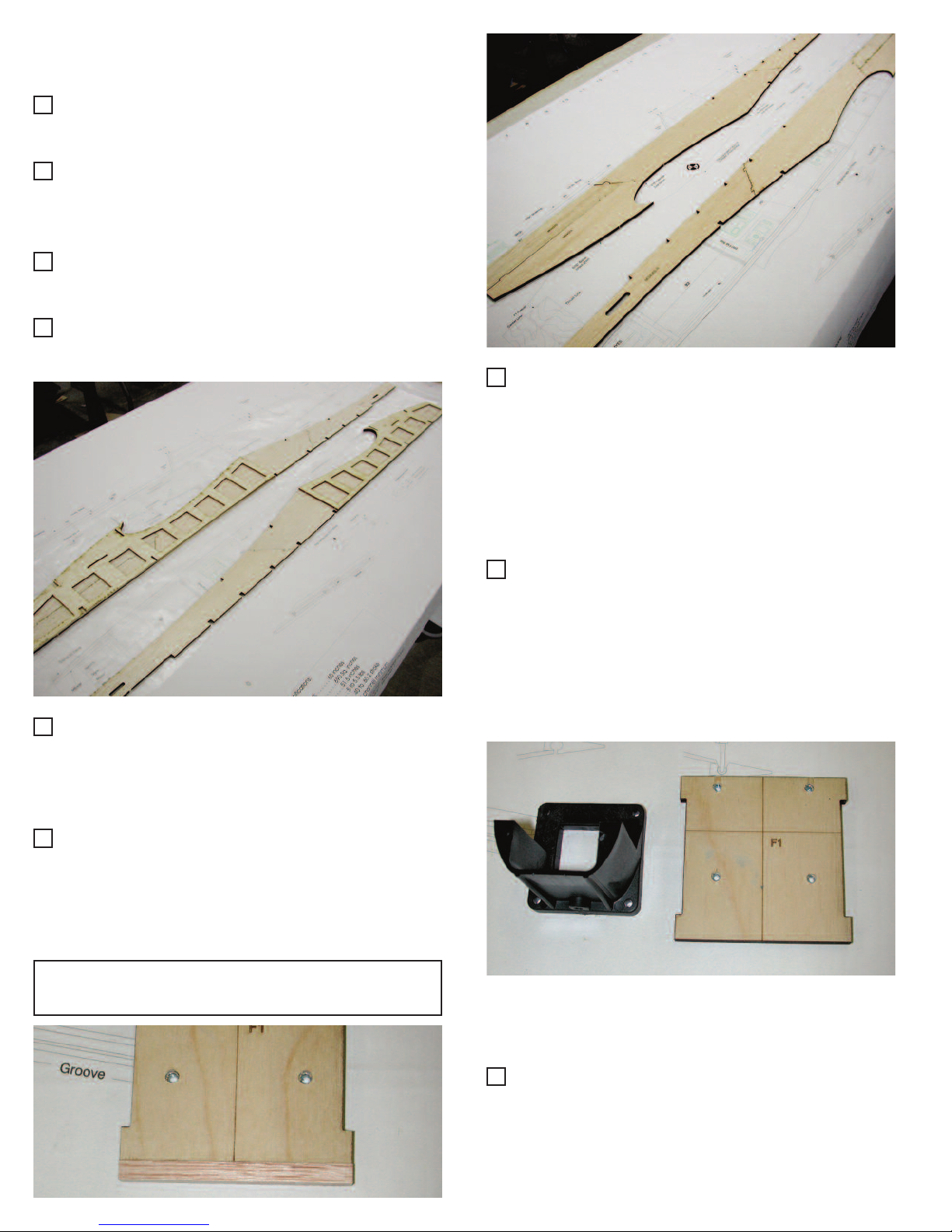
7. Locate F1 Firewall and align your engine
mount with the scribed lines on firewall. Drill
holes and install motor mount as instructed
by the mount manufacturer.
8. Using the steering arm as a guide, mark the
location of the steering cable exit. Drill two
holes for the fuel line and one hole for the
engine throttle. If you have a long drill bit,
you can also drill these holes later.
Taildragger Version:
Don’t drill any holes for the steering cable.
6. Remove the doublers and apply a thin layer
of 30 minute epoxy to each FD1. Re-align
with the fuse sides and allow to cure. Make
sure you wipe any excess epoxy from the
slots in FD1. You will use these slots for
alignment of the bulkheads later.
9. Add a piece of 1/4” sq. balsa to the bottom
of F1 and sand even with all sides. This will
allow you to contour the firewall to the bottom of the fuselage easier.
14

10. Locate B1B and B1A. Glue B1A to B1B
with thick CA or 5 minute epoxy. Use a 1/4”
dowel to insure the holes in each piece
align.
11. Locate B2, B3, and C1. Take left side on
fuselage and insert F1 and B1A/B assembly into the tabs as shown on the plan.
Next, insert B3 into the appropriate slot.
Make sure the wide end is butting up
against B1B and resting below B1A.
Remember the fuselage is built upside
down, so make sure the firewall is facing
the correct way.
13. Align the right fuselage side with F1, B1B,
B2, B3 and C1. Once everything is square
with C1 and the plan, clamp and glue all
joints from F1 to B2 with medium CA or 5
minute epoxy.
12. Place C1 on the plan and pin in place with
the scribed lines facing down. Align the left
fuselage assembly with C1 and place B2 in
the location shown on the plan.
Note: If you are using the supplied flexible
pushrods, insure the 2 round holes in B2 are closest to C1. If you are making control rods from
dowels, turn B2 so the rectangle cutout is closest
to C1.
15

14. Carefully align wing in saddle. Using 1/4”
dowel hole in B1A/B as a guide, drill a 1/4”
hole into the front of the wing. Remove
wing and epoxy the dowel into the wing
leaving 5/8” protruding. Set wing aside.
15. At the back of B2, score the balsa sides
about half way through on the inside. This
will allow you to bend the fuselage easier.
16. Wet the outside and bring the fuse side
into alignment with the plan. Glue with
medium CA at the tail.
17. Locate and glue with 5 min epoxy PW so
that it fits flush with the top of the cut-out for
the horizontal stab. This can be done while
the fuselage is pinned to the building surface or you can unpin the fuselage and turn
it over as show in the photo.
18. Using the 1/4” sq. x 36” balsa sticks, cut
and sand fuselage cross pieces to match
the plans for the top and bottom of the
fuselage sides.
16

19. Insert the 1/4” sq. pieces into the slots on
the fuselage sides and align so they are
flush. Glue with thin CA. Glue rear 1/4”
piece as shown on plans and in the inset
photo.
Note: If you removed the fuselage from the building surface during step 17. Make sure it is pinned
down and aligned with the plans for step 19.
20. Cut and fit 1/4” sq. vertical pieces and glue
to B2 and fuselage sides.
21. Using 3/32” balsa sheet pieces, sheet the
fuse bottom from B2 back to the tail. Insure
the grain is running crossways.
Taildragger Version:
Using scrap 1/8” ply, place on the bottom of the
fuselage at the very rear, mark shape and sand
to fit. Glue in place for tail wheel mount.
22. Once all pieces are glued and trimmed,
sand flush with sides. Remove fuse from
building surface.
23. Locate the two 7/8” x 1/2” x 1-5/8” wing
hold down blocks. Bevel each block so it
will fit flush with B2 and parallel with wing
saddle.
24. When satisfied with fit, use 5 minute epoxy
to glue blocks in place 1/32” below wing
saddle and flush with B2. Let dry.
17

25. Place wing onto fuselage. The wing dowel
will align the front and the wing joint should
align with the center of the fuselage. To be
very sure, you can use the method shown
in figure 1.
26. Once you have the wing centered, mark
where shown on the plan and drill two wing
bolt holes. Use a #7 numbered or 13/64”
fractional drill bit. If you do not have these
drill sizes you can use a 3/16”, but you will
have to be careful tapping the smaller hole.
27. Remove the wing and drill the wing only to
1/4”.
28. Using a 1/4-20 tap, tap the wing blocks.
Note: After tapping, clean the treads and apply
thin CA. Allow plenty of time to cure and re-tap.
This will give you good, strong threads.
32. Locate C3 (2 ea.) servo mounting backup
plates and glue with medium CA to each
side of the servo mounting holes in C1.
You can glue them to either side of C1.
Figure 1
29. Sand the balsa filler on the bottom of F1 so
it is flush with the fuselage sides.
30. Sheet the bottom of the fuselage from the
wing saddle to F1 as shown in photo.
31. Locate CS1 balsa strips and cap strip the
bottom of each fuselage side in front of F1
so they become flush with the bottom
sheeting.
18

33. Run the flexible control rods from the holes
in the rear of the fuselage to the holes in
B2. Glue in place with medium CA.
34. Locate turtle formers 1A and 1B. Place 1B
on top of 1A. Using 3/16” balsa stringers
as spacers center both pieces. Mark location and glue.
35. Bevel bottom of 1A/1B assembly. Center
and glue TG backrest flush with bottom.
37. Remove turtle formers 2,3,4,5,6, 7A & 7B
from 1/8” ply sheet. Glue 7A and 7B together so they align with each other.
36. Align the front of TG to the scribed line in
C2. Adjust the length of TG to fit around
C3. Glue in place with medium CA.
19

38. Glue formers 2 thru 7 in place (see plan).
Make sure they are centered with the
stringers and the fuselage sides. Also
insure that they stand at 90 degrees from
the fuselage side.
39. Locate five 3/16” sq. stringers. Cut and
sand to fit in the notches of turtles 1 thru 7.
40. Starting with the top stringer, use thin CA
to glue each stringer in place. Use 5 min
epoxy to reinforce the stringers to turtle 7.
Note: For a more finished look and increased
strength, you can also sheet the turtledeck with
1/16” balsa.
41. Install the flexible pushrods for the steering
and throttle cable at this time.
42. Now you are ready to install the fuel tank.
Assemble fuel tank and set tank into the
tank compartment. Determine necessary
foam padding to hold tank in the center so
that it will be even with the engine carburetor. Run fuel lines through the firewall.
Note: The fuel tank should have foam on the bottom and sides to prevent fuel foaming and a poor
running engine.
20

43. Locate two B6 cowl formers. Align and glue
them to each other as shown.
44. Align B4 with the scribed line on C1 and
sand the bottom of B4 so it will match the
angle shown on the plan [8L]. Glue B4 to
C1 aligning it with the scribed line. Test fit
B5 4” back from F1 and glue in place. You
may need to cut part of B5 so the fuel tank
will fit. Align and glue the B6 assembly on
top of F1.
45. Locate a 1/4” sq. x 36” stringer and cut to
fit between B4 and B6. Align and sand so
the stringers are flush with the top edge of
B4. Glue stringers to B4, B5 and B6 with
medium CA.
46. Sand stringers flush with the curve in B4
thru B6.
47. Cut 3/32” sheeting to fit over the cowl
stringers and flush with the fuselage sides.
Bevel the edges of the 3/32” sheeting so
they will fit flat on the fuselage sides.
Apply medium CA to the stringers and
fuselage sides and press the sheeting in
place.
Note: You may need to use water or window
cleaner on the outside of the sheeting so that it
will curve around the formers.
21

48. Sand sheeting flush with B4 and B6.
49. You can use the 1/4” B7 pieces to taper the
front of the cowl if you desire.
50. Glue two pieces of (one on each side) 1/4”
sq. x 5-1/2” on the top ends of C1 between
B4 and turtle 1 to form the cockpit sides.
51. Re-mount the wing on the fuse. Place the
horizontal stab on the fuse. Sight from the
rear and make certain the horizontal stab is
parallel with the top of the wing. This is
important for straight flight. Carefully sand
the stab saddle so the horizontal stab sits
level.
52. Remove horizontal stab and align TS2 (90
degrees) on TS1 along the scribed line so
they form a T shape.
53. Place the spacer assembly on the stab
saddle and center it at the front and rear of
the saddle. When perfectly centered, pin
the rear and front ends to the fuse.
22

54. Locate the two faring blocks (5/8” x 1” x 57/8”). Place them on both sides of the
spacer and flush with the back of turtle 7.
Glue the blocks to turtle 7 ONLY. Sand to
match the contour of turtle 7 and the angle
of the stringers. These blocks will hold your
vertical and horizontal stab in place.
55. Once the blocks are sanded to shape,
remove and discard the spacer. The blocks
should now have a taper that matches the
stringer angle as shown in photo. Sand the
rear of the blocks to match the fuselage
length.
56. Remove the 1/8” ply triangles and servo
plate from the laser cut sheet. Assemble
them as shown in the photo (use medium
CA). This assembly can be glued to the
fuselage side and used to mount your
throttle servo.
23

Finishing and final assembly
1. Sand the entire model to a smooth surface. Carefully
remove all sanding dust to allow proper adhesion of
your covering material.
12. Install the rudder and elevator pushrods and clevises. Make sure the control surfaces and servos are
in a neutral position when the radio is turned on.
13. Install the throttle cable and nose gear cable.
2. Cover your Fantasy with your choice of covering.
Follow the manufacturer’s instructions for the covering used.
3. In order to fuel proof the engine compartment, it is
easier to use a painted or epoxy finish rather than
applying film. You can use a coat of 30 minute epoxy
thinned with denatured alcohol or any fuel-proof paint
to seal the wood.
4. Remove the covering on top and bottom of the stab
and bottom of the fin where they are to be glued to
the fuse. Note: Be very careful not to score the wood
as it may cause failure of that surface in flight.
5. Use 30 minute epoxy to glue stab and fin in their
proper location. Before the epoxy cures, sight across
the rear of the stab to insure it is parallel with the
wing. Verify the fin is 90 degrees to the stab. Use
masking tape to hold the stab and fin in place.
6. Install rudder and elevator control horns where shown
on plan.
7. Hinge the elevator first using the provided hinges.
With a hobby knife, slit the film covering where each
hinge slot is located. Install one hinge in each slot of
the stab (halfway). Slide the elevator into position.
When fully seated, deflect the elevator to the maximum throw you will be using and put 3 or 4 drops of
thin CA on each hinge. Hold the elevator in the
deflected position until dry. Next turn aircraft upside
down and deflect the elevator in the opposite direction. Add 3 or 4 more drops of thin CA to that side of
the hinge and allow to dry.
8. Install the rudder using the same process as in step
7.
14. Install the aileron pushrods as described in the manufacturer’s instructions.
15. Cut out the canopy and fit it over the cockpit area.
Trim as necessary for a good fit. Use a few small
pieces of masking tape to hold the canopy tight to
the fuselage and go around the canopy edge with
RC-56 glue. Keep an eye out for drips until the glue
has thickened. Once the glue has dried completely,
you can use trim tape around the edge of the
canopy for a finished look.
16. Install landing gear wires, using landing gear straps
for mains and wheel collar/steering arm for nose
gear. Attach wheels.
17. Install engine, balanced prop and spinner.
18. Set the deflection of your control surfaces to the
measurements shown on the fuselage plan.
19. Balance the aircraft. The plane should be turned
upside down at balanced where the fuselage meets
the wings 7-1/2” in front of the trailing edge (5” back
from the leading edge). Do not attempt to fly a plane
that is not balanced withing the points shown on the
plans.
We hope that you enjoyed building your lasercut Fantasy because the best is yet to come!
Your input on the instruction, plans and flight is
very valuable to us and would be greatly
appreciated.
9. Install the ailerons using the same method used in
step 7. In addition, put a small amount of epoxy in the
aileron torque rod hole in order to secure it and keep
it from wearing the balsa on the aileron.
10. Install radio equipment where shown on the plan. Be
sure to follow the radio manufacturer’s instructions.
Wrap the receiver and battery in 1/4” or 1/2” foam
rubber to protect them from vibration. We use Hitec
475BB standard ball bearing servos and standard
Hitec 8 channel receiver in our prototype. There is
no need to use hi-torque servos in this aircraft.
11. Cut a hole in the side of the fuselage opposite the
exhaust for the on/off switch and charger jack.
24
 Loading...