

Skyros VideoNet 9.1 Installation Manual
1
SKYROS Corporation VideoNet Web Server 2.1 Руководство пользователя
РУКОВОДСТВО ПОЛЬЗОВАТЕЛЯ

1
Installation manual
SKYROS Corporation VideoNet 9.1
This document is for information purposes only.
SKYROS Corporation offers no extra warranties concerning the information
provided herein.
VideoNet®, TinyVN4, PowerVN4, TitanVN8, PowerVN8, TitanVN16, DVPack™
and the documentation related to them are protected by Copyright of SKYROS
Corporation © 2014 to this day. All rights reserved.
Windows is a registered trademark of Microsoft Corporation (of the USA or
other countries).
HASP is a registered trademark of Aladdin Knowledge Systems Ltd. Conexant,
Fusion 878A, and CX23880 are the trademarks of Conexant Systems, Inc.
Intel and Pentium are registered trademarks and MMX is a trademark of Intel
Corporation.
Any other trademarks, brands, and product names used in this document are
the trademarks of their respective owners.
VideoNet 9.1
January 2017
SKYROS Corporation
Telephone: +7-800-505-01-00
+7-812-448-10-00
+7-812-448-10-10
Fax: +7-812-448-10-12
Web: support@videonet9.com
www.videonet9.com

SKYROS Corporation VideoNet 9.1
2
Installation manual
CONTENTS
1. TECHNICAL REQUIREMENTS TO THE SYSTEM ........................................... 3
2. ACTIONS SEQUENCE DURING VIDEONET INSTALLATION .........................4
3. HARDWARE INSTALLATION ...........................................................................4
3.1. Video/audio blasters types ........................................................................... 5
3.1.1. PowerVN4 Pro2 video/audio capture card ......................................... 8
3.1.2. PowerVN4 Pro3 video/audio capture card ....................................... 16
3.1.3. PowerVN4 Pro4 video/audio capture card ....................................... 18
3.1.4. PowerVN4-AHDM video/audio capture card ................................... 20
3.1.5. PowerVN8 / PowerVN8 LP video/audio capture card .....................22
3.1.6. PowerVN8-AHDM video/audio capture card .................................... 25
3.1.7. PowerVN8-HD video/audio capture card .........................................27
3.1.8. TitanVN8 video/audio capture card .................................................. 29
3.1.9. TitanVN8 Pro video/audio capture card ........................................... 31
3.1.10. TitanVN16 / TitanVN16 Rev. 1.4 video/audio capture card ............ 33
3.1.11. TinyVN4 Pro2 video/audio capture card ......................................... 36
3.1.12. TinyVN4 Pro3 video/audio capture card .........................................37
3.1.13. Additional panels ............................................................................39
3.1.13.1. Additional video inputs MB-BNC4 panel ..........................39
3.1.13.2. Additional video inputs MB-BNC4 AGC panel .................40
3.1.13.3. Additional audio inputs MB-RCA4 panel .......................... 41
3.1.13.4. Additional video/audio inputs MB-DB25 panel ................. 41
3.1.13.5. Additional video/audio inputs MB-DB25 AGC panel ........43
3.1.13.6. MB-RIO 4/16 unit of relay outputs and insulated inputs ...44
3.1.13.7. MB-RIO 4/16 - USB rev.3.1 card of relay outputs and
insulated inputs ................................................................47
4. SOFTWARE INSTALLATION ..........................................................................50
4.1. Initial software installation ..........................................................................50
4.1.1. VideoNet Autostart Service ..............................................................60
4.2. Archive Conguration Parameters .............................................................61
4.3. Windows User Rights ................................................................................. 64
4.4. Interaction of the VideoNet 9.1 with the older VideoNet systems ..............64
4.5. Security of the VideoNet system ................................................................ 65
4.6. Software Removal ...................................................................................... 65
5. CONNECTING EXECUTIVE DEVICES ...........................................................67
5.1. Connecting Panasonic WV CS850, Panasonic WV CS600 cameras ....... 68
5.2. Connecting LiLin PIH7000/7600 dome cameras ......................................68
5.3. Connecting Fastrax dome cameras ..........................................................69
5.4. Connecting Pelco DD5 dome cameras ..................................................... 69
5.5. Connecting Samsung SCC-643 dome cameras .......................................70
5.6. Connecting KT&C cameras by the example of KPC- 202CZH .................. 71
5.7. Connecting HITACHI D-7722 dome cameras ...........................................71
5.8. Connecting JVC TK-C676 dome cameras ................................................ 72
5.9. Connecting Galact dome cameras ............................................................ 72
5.10. Connecting GANZ ZC-S122/123 dome cameras .................................... 73
5.11. Connecting CNB cameras ....................................................................... 73
5.12. Connecting Panasonic WV-CU650 system controller ..............................74

3
Installation manual
SKYROS Corporation VideoNet 9.1
1. TECHNICAL REQUIREMENTS TO THE SYSTEM
Hardware and software requirements for the computer on which the VideoNet
system will be installed are as follows:
Attention! Antivirus software that automatically scans les on the computer can
signicantly reduce the system’s recording and playback performance. In case
of using such software, it is recommended to (depending on available settings):
• disable the check of volume les (.vnsd);
• disable the check of all les, leaving only the check of program les;
• disable the check of the disks on which volume les are located;
• disable automatic check for all disks.
CPU Minimum: Intel Core i3 530 processor
Recommended CPU parameters depend on the required number of
connected cameras.
RAM Minimum: 2 GB for 32-bit OS and 4 GB for 64-bit OS
For 64-bit operating system is recommended: 8 GB for systems with up to
16 cameras, 16 GB for systems with up from 16 cameras to 32 cameras,
32 GB for systems with over 48 cameras
Attention! When you use video capture cards, the PAE mode must be disabled.
Attention! Pre-recording requires additional RAM size (see Section 3.2.2.5 of the
User guide).
Operating
system (32 bit)
Windows 7 SP1 (Professional, Ultimate, Enterprise), Windows 8 (Core,
Pro, Enterprise), Windows 8.1 (Core, Pro, Enterprise), Windows 10 (Home,
Pro, Enterprise)
Operating
system (64 bit)
Windows Server 2008 R2 SP1, Windows Server 2012, Windows Server
2012 R2, Windows Server 2016, Windows 7 SP1 (Professional, Ultimate,
Enterprise), Windows 8 (Core, Pro, Enterprise), Windows 8.1 (Core, Pro,
Enterprise), Windows 10 (Home, Pro, Enterprise)
Note: Only PowerVN4/8-AHDM, PowerVN8, PowerVN8-HD, TitanVN16 capture cards
and cards with Cx2388x chip are supported.
Graphics card Minimum: OS-determined (128 MB, DirectX 9 support)
Note: To select the graphics card chipset manufacturer, it is recommended to use the
list of tested equipment (Support).
Display Minimum: 1280х1024
File system NTFS; it is recommended to use a 64 KB cluster size for formatting the
disks on which video archive volume les are placed.
Attention! Other le systems are not supported.
Note: It is recommended to disable the system recovery feature on logical disks on
which video archive volume les are placed.
Note: It is recommended to install Battery BackUp Unit, if you use RAID controllers.
Database
Management
Systems Used
Microsoft SQL Server 2008
Microsoft SQL Server 2008 R2
Microsoft SQL Server 2012
Microsoft SQL Server 2014
Microsoft SQL Server 2016
Attention! Starting resource-intensive applications on the same computer may
adversely affect the VideoNet system’s performance. It is not recommended
to install third-party applications, other than those which are part of Windows,
on this computer.
SKYROS Corporation VideoNet 9.1
4
Installation manual
2. ACTIONS SEQUENCE DURING VIDEONET INSTALLATION
To install VideoNet system it is necessary to perform the following actions:
1. Switch off your computer.
2. Install inyVN4, TinyVN4 Pro, TinyVN4 Pro2, TinyVN4 Pro3, PowerVN4,
PowerVN4 Pro, PowerVN4 Pro2, PowerVN4 Pro3, PowerVN4 Pro4,
PowerVN4/8-AHDM, PowerVN8, PowerVN8-HD, TitanVN8, TitanVN8 Pro
or TitanVN16 video capture cards (refer to 3.1 section). Install if necessary
additional video/audio inputs panels or additional panels for working with relay
outputs and alarm sensors (refer to 3.1.12 section). Connect also necessary
executive devices (dome cameras, refer to chapter 5).
3. Switch on your computer.
4. Launch VideoNet Installation wizard (refer to chapter 4).
5. Put HASP key into USB port of your computer only at the request of VideoNet
Installation wizard.
6. Restart your computer after completing the installation process.
3. HARDWARE INSTALLATION
Computer, to which CCTV cameras and microphones will be connected, must have
one or more video blasters of Tiny, Power or Titan family installed. Third-party
manufactured video blasters on Conexant Fusion Bt878, Bt878A, Bt879 chips
To improve the VideoNet system’s performance, it is recommended to install
Microsoft DirectX Version 9.0c or later on the computer. You can nd the
DirectX setup program on Microsoft’s website.
Attention! The work of audio/video capture cards with Bt chips on the last
generations motherboards is not guaranteed.
If you want to add capture cards to the VideoNet system conguration and
you are using Windows 7 SP1 or Windows Server 2008 R2 SP1, the update
KB3033929 must be installed on your computer. You can nd the update on the
installation disk or on Microsoft’s website (https://technet.microsoft.com/en-us/
library/security/3033929.aspx).
Attention! It is not recommended to use Punto Switcher when you work with
VideoNet.
Attention! When working with VideoNet system, it is recommended to use a
64-bit operating system.
To learn more about the hardware requirements for your VideoNet surveillance
solutions, you can use a calculator on the website http://www.videonet.ru.
Attention! The integration of FSA controllers into VideoNet 9.1 system is carried
out only on the computers running the Windows 7 SP1 operating system in
accordance with the NVP “Bolid” requirements. You can nd the requirements on
the NVP “Bolid” website (http://bolid.ru/production/orion/po-orion/po-integration/
modul_upr_s2000.html#characteristics).
5
Installation manual
SKYROS Corporation VideoNet 9.1
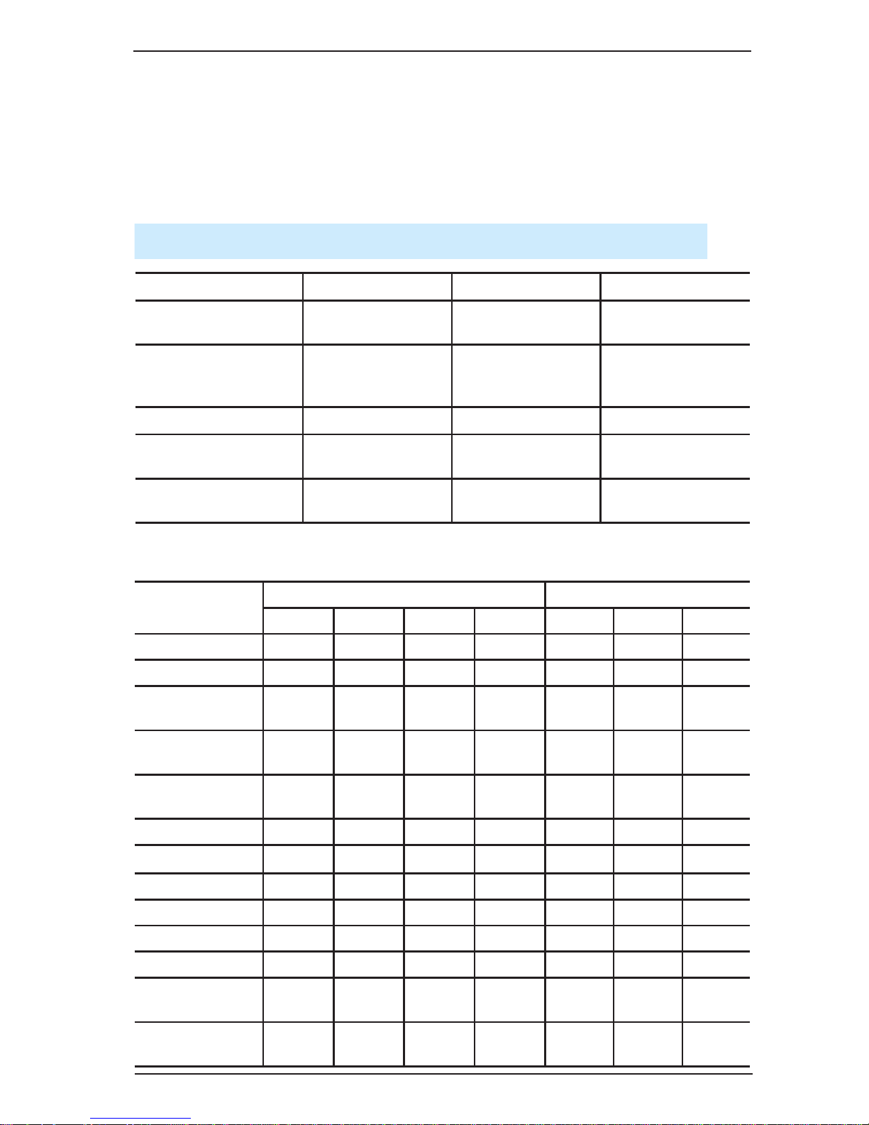
3.1. Video/audio blasters types
Table 1. Video/audio blasters types.
Power Titan Tiny
cards with Bt8xx chip
VN4
VN4 Pro
VN8
VN4
VN4 Pro
cards with Cx23880
chip
VN4 Pro2
VN4 Pro3
VN4 Pro4
VN8 Pro
VN4 Pro2
VN4 Pro3
cards with DSP TMS VN8 VN16
cards with NVP6114
chip
VN4/8-AHDM
cards with RN6318A/
RN6598 chip
VN8-HD
Parameters
Tiny family Titan family
VN4 VN4 Pro VN4 Pro2 VN4 Pro3 VN8 VN8 Pro VN16
Chip Bt8xx Bt8xx Cx23880 Cx23880 Bt8xx Cx23880 TMS
Number of chips 1 1 1 1 8 8 4(16)***
Motherboard slot
PCI
32/33
PCI
32/33
PCI
32/33
PCI
32/33
PCI
64/66
PCI-E PCI-E
Video inputs in
real-time mode
1 1 1 1 8 8 8 – 16 **
Switchable video
inputs
4 4 4 4 32 32 32
S-Video inputs – – 1 1 – 8 –
Audio inputs 1 1 2 2 8 16 16
Alarm sensors – 16 – 16 32 32 32
Relay outputs – 4 – 4 8 8 8
LEDs – + – + + + –
Watchdog timer – + – + + + +
MB-RIO 4/16
connection
– 1 – 1 2 2 2
MB-BNC4
connection
– – – – + + –
are also supported. All drivers for mentioned video blasters will be installed during
the installation process. Using third-party manufactured drivers of third-party for
mentioned video blasters is not permitted. Before starting the installation process,
make sure that there are no third-party manufactured drivers. Otherwise, it can cause
incorrect installation, leading to the operation system inoperability.

SKYROS Corporation VideoNet 9.1
6
Installation manual
Table 3. Parameters of video/audio blasters of Power family.
MB-RCA4
connection
+ + + + + + +
MB-DB25 (video)
connection
– – – – + + +
MB-DB25 (audio)
connection
+ + + + + + +
Connecting panel
for working with
S-Video
– – + + – + –
Table 2. Parameters of video/audio blasters of Titan and Tiny families.
Parameters
Power family
VN4 Pro2 VN4 Pro3 VN4 Pro4
VN4/8AHDM
VN8 VN8-HD
Chip
Cx23880 Cx23880 Cx23880 NVP6114 TMS RN6318A/
RN6598
Number of chips 4 4 4 1/2 2(8)*** 1
Motherboard slot
PCI
64/133
PCI-E
PCI
32/66 (*)
PCI-E PCI-E PCI-E
Video inputs in realtime mode
4 4 4 4/8 4 – 8 ** 8
Switchable video
inputs
16 16 16 – 16 –
S-Video inputs 4 4 4 – – –
Audio inputs 8 8 8 4 8 4
Alarm sensors 16 16 16 –/16 16 16
Relay outputs 4 4 4 –/4 4 4
LEDs + + + – – –
Watchdog timer + + + – + –
MB-RIO 4/16
connection
+ + + –/+ + +
MB-BNC4 connection + + + – – –
MB-RCA4 connection + + + – + –
MB-DB25 (video)
connection
+ + + – – –
MB-DB25 (audio)
connection
+ + + – + –
Connecting panel for
working with S-Video
+ +
+ – – –
7
Installation manual
SKYROS Corporation VideoNet 9.1
By installation this card into motherboard slot, supporting 64/66 standard, bus
capability remains 66 MHz.
Number of inputs in real-time mode depends on license. In detail VideoNet license
restrictions are described in the 2.3 section of the User guide.
The number specied is the number of chips and ADCs contained in them. The
number of chips in video capture cards with Bt and Cx chips is equal to the
number of ADCs.
*
**
***
Attention! For 32-bit systems, it is recommended to add to the VideoNet
conguration only that amount of video capture cards with Bt chips, that contain
no more than 8 chips in total.
Attention! You can learn about the parameters PowerVN4 and PowerVN4 Pro
cards in the documentation to VideoNet 8.9 Service Pack 1 and earlier systems.

SKYROS Corporation VideoNet 9.1
8
Installation manual
3.1.1. PowerVN4 Pro2 video/audio capture card
PowerVN4 Pro2 card is a video/audio capture device, intended for digital capture
of audio and video signals, received from cameras and microphones, connected to
it. Also the card is a sensors controller and a relay outputs controller, and thereby
enables to control sensors and relay outputs, connected to its inputs.
Cameras, transmitting composite signal or signal in S-Video format, are to be
connected to video inputs. Microphones are to be connected to audio inputs.
Connecting relays and sensors to corresponding card outputs/inputs is performed
through additional panels MBRio.
The card consists of 4 independent CX23880 devices, intended for digital capture of
audio and video signals. Each device can work independently both in the switchable
mode (12 fps) and in the non-switchable mode (25 fps). Thus, maximum frame ow
for a card is 100 fps.
On the card there are:
• 4 main video inputs for working with composite video signal in the real-time mode;
• 12 additional video inputs for working with composite video signal in the
multiplexing mode (these inputs can be used for working with brightness
component of S-Video signal);
• 4 inputs for working with colour-difference component of S-Video signal;
• 8 inputs for working with audio signal;
• 4 relay outputs and 16 alarm sensors inputs.
PowerVN4 Pro2 card must be installed into the PCI slot of motherboard of your
computer.
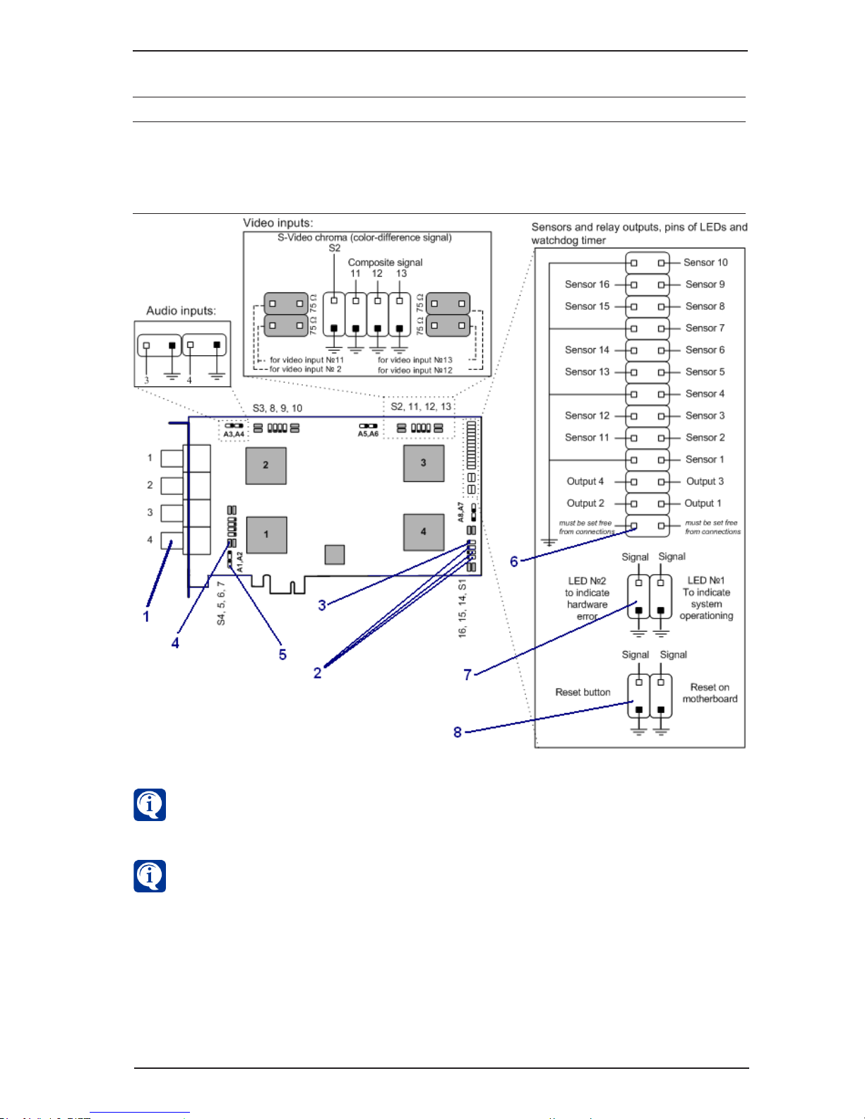
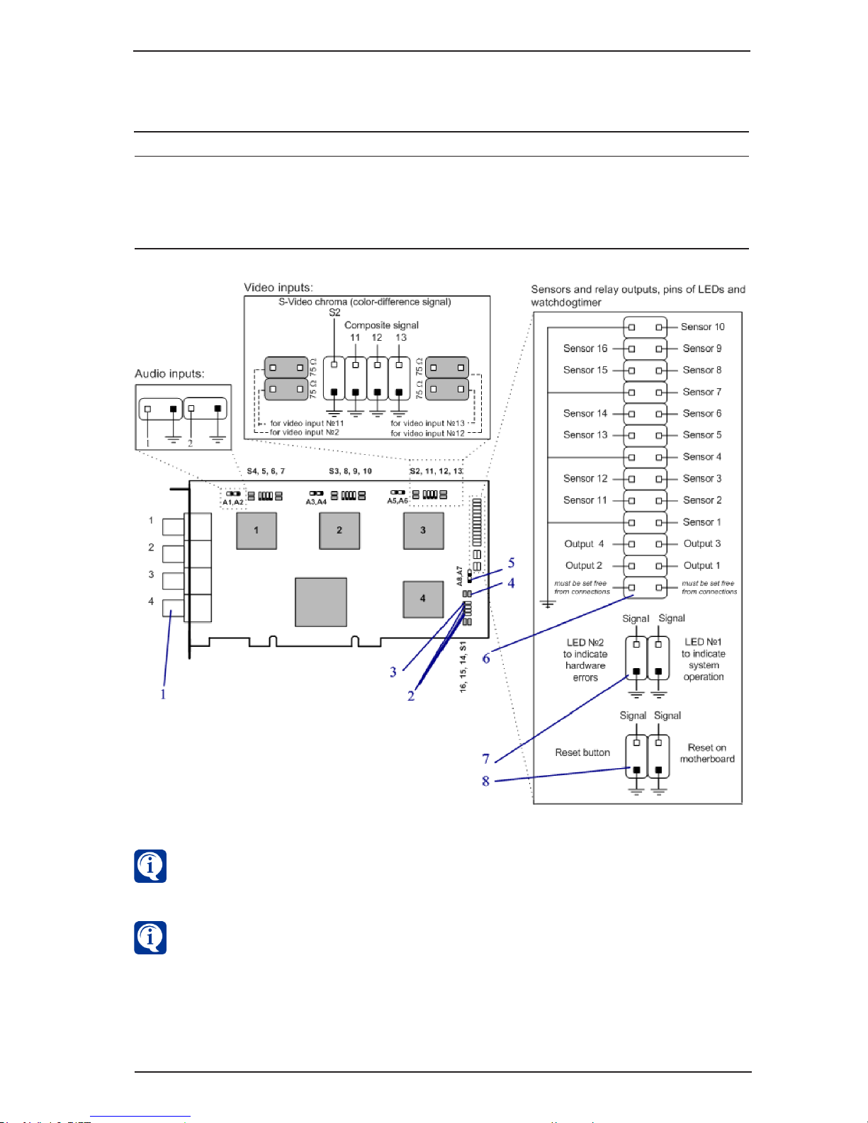
The card diagram is shown in the picture 3.1.1:
•main (1) and additional pin connectors for composite video signal (2) and for
S-Video signal (3);
•jumpers for switching on/off 75 Ohm load (4);
•audio inputs (5)
•connectors for sensors and relay outputs (6);
•LEDs pins (7);
•Watchdog timer pins (8).
PowerVN4 Pro2 card supports working both with S-Video signal and with composite
signal.
For composite signal inputs 1-4 are used in the non-switchable mode and inputs
5-16 are used in the switchable mode.
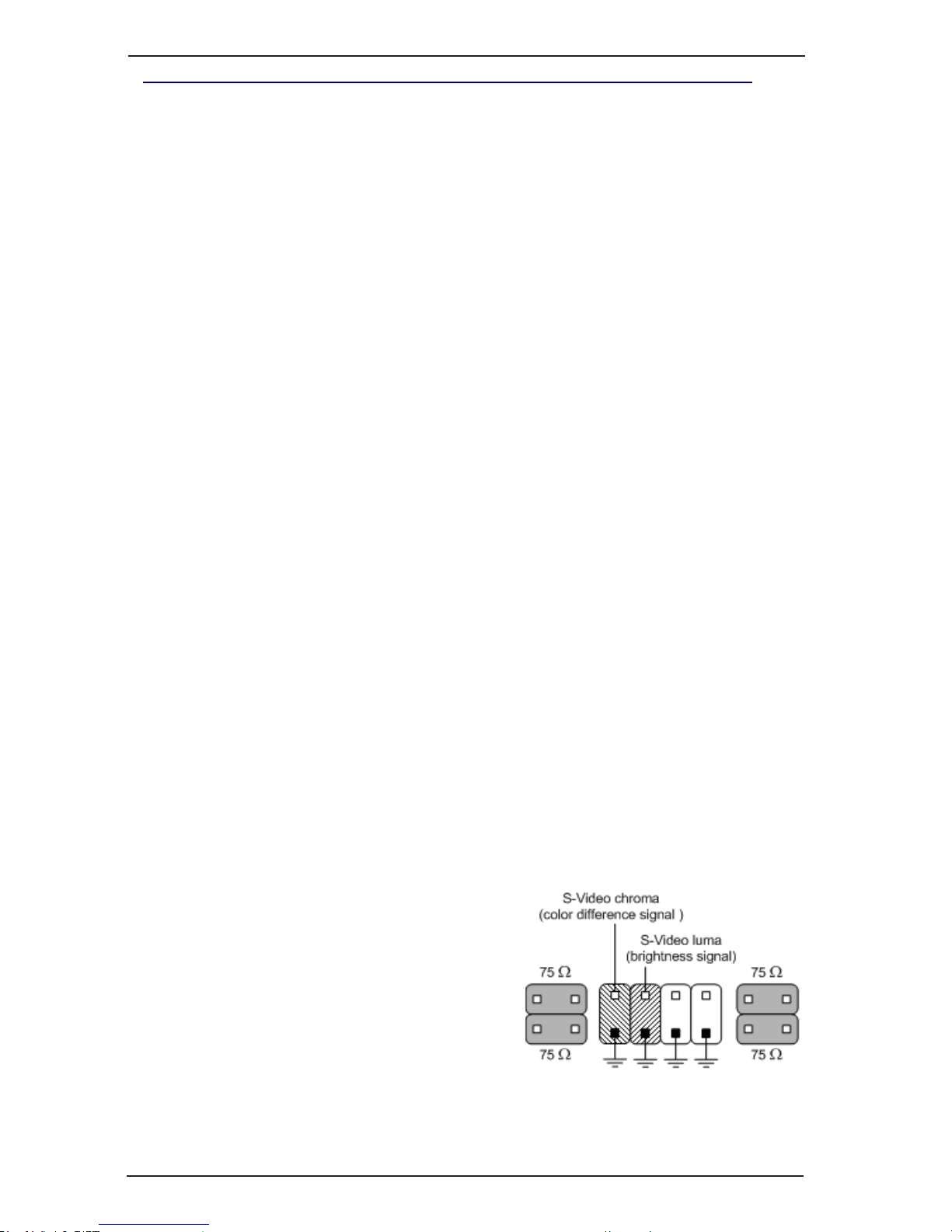
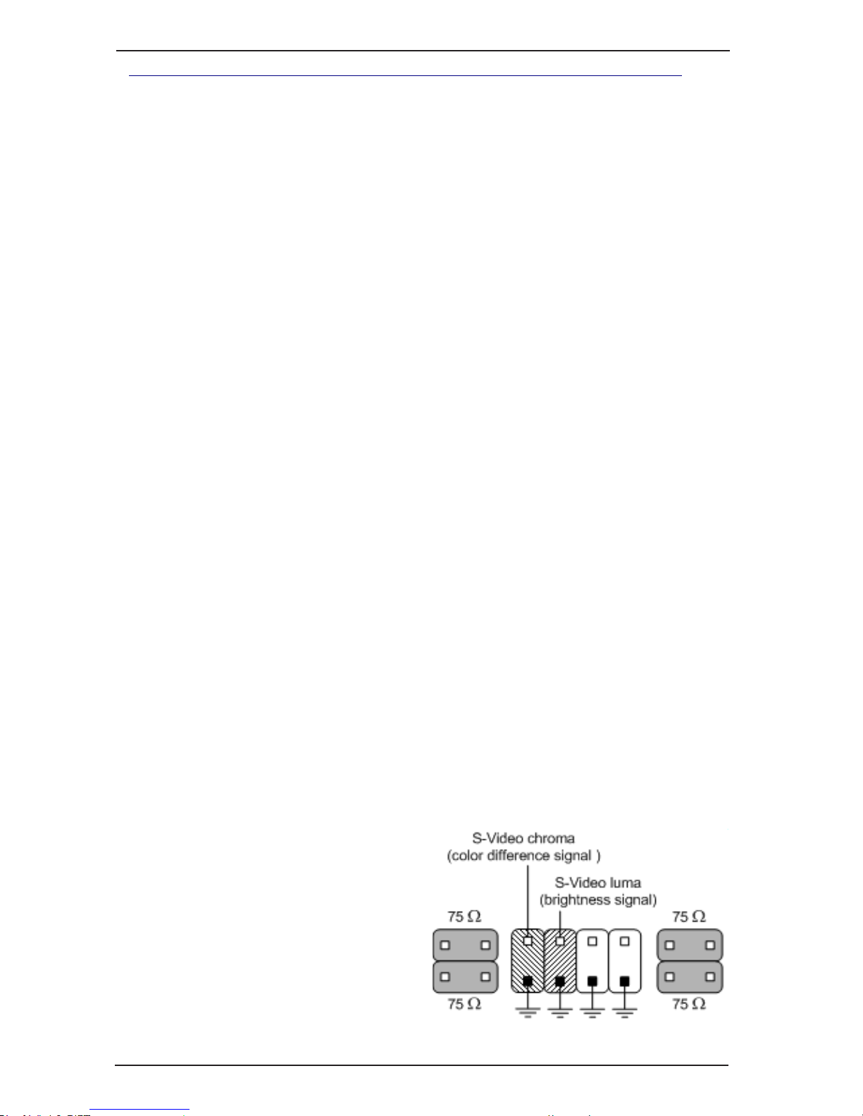
For working with S-Video signal S1-S4 video
inputs are used for the colour-difference
component (S-Video chroma) and appropriate
14, 11, 8, 5 video inputs are used for brightness
component (S-Video luma). When connecting it
is necessary to use an additional video inputs
panel for working with S-Video signal.
Attention! CX23880 chip, working in S-Video
mode, can’t simultaneously work with composite
signal.
For working with audio signal A1–A8 inputs are used.
There are 4 video inputs on each CX23880 device on the PowerVN4 Pro2 card.

9
Installation manual
SKYROS Corporation VideoNet 9.1
Let’s consider connecting cameras and microphones to PowerVN4 Pro2 video/
audio capture card with specic reference.
A. If you want to connect 4 cameras for working in the real-time mode (25 fps)
1. Connect 4 cameras to the card main inputs (1-4 inputs in picture 3.1.1). During
such connection each of four CX23880 devices will work in the real-time mode
and ow by each camera will be 25 fps.
Use if necessary additional MB-BNC4 and MBDB-25 panels for video signals
connection or additional MB-RCA4 and MBDB-25 panels for audio signals
connection.
Use additional MB-RIO 4/16 units for working with alarm sensors and relay
outputs.
Picture 3.1.1. PowerVN4 Pro2 card connectors location.
Correspondence between inputs numeration on the card and in the VideoNet system
is shown in the table below:
CX2388х device number
1
2
3
4
Video inputs numeration
4, 5, 6, 7
3, 8, 9, 10
2, 11, 12, 13
1, 14, 15, 16
Audio inputs numeration
1, 2
3, 4
5, 6
7, 8

SKYROS Corporation VideoNet 9.1
10
Installation manual
2. Add PowerVN4 Pro2 video capture card to VideoNet system conguration;
multiplexing mode must be switched off in the card properties; S-Video mode
must be switched off for each device.
Add 4 cameras to system conguration and connect them in the device tree
(on the Devices page) to 1-4 inputs. In more detail adding, connecting and
conguring device parameters are described in the User guide, 3.1 section.
B. If you want to connect 8 cameras for working in the multiplexing mode
1. Connect 4 cameras to main 1- 4 inputs of PowerVN4 Pro2 card and 4 cameras
to inputs of additional MB-BNC4 video inputs panel. Connect outputs of the
additional panel to inputs 5, 8, 11, 14 on the PowerVN4 Pro2 card. Connections
diagram is shown in the picture 3.1.1-1.
In case of such connection the card will work in the switchable mode with a
ow of 12 fps on each CX23880 device.
It is important to understand that at connecting more than one camera to one
CX23880 device, the device works in the multiplexing mode – frames ow by
each of connected cameras reduces.
Thus, for example, if one device has:
1 camera connected – the ow will be 25 fps (the real-time mode);
2 cameras connected – 6 fps (multiplexing mode);
3 cameras connected – 4 fps (multiplexing mode);
4 cameras connected – 3-4 fps (multiplexing mode).
That’s why when connecting a large number of cameras it is important to
correctly distribute them among four devices.
If in the example above you connect cameras to the following inputs:
4, 5, 6 (device 1),
3, 8 (device 2),
2, 11 (device 3),
1 (device 4),
then by cameras, connected to:
device 1 we will have 4 fps,
device 2 we will have 6 fps,
device 3 we will have 6 fps,
device 4 we will have 25 fps (real time).
2. Add PowerVN4 Pro2 video capture card to VideoNet system conguration;
multiplexing mode must be switched on in the card properties; S-Video mode
must be switched off for each device.
Add 8 cameras to system conguration and connect them in the device tree
(on the Devices page) to 1-4 and 5, 8, 11, 14 inputs of the PowerVN4 Pro2
card. In more detail adding, connecting and conguring device parameters are
described in the User guide, 3.1 section.
C. If you want to connect 4 cameras for working with S-Video signal
1. Connect 4 cameras to inputs of additional panel for working with S-Video signal.
Two outputs correspond to each input of the additional panel: colour-difference
component output and brightness component output – 8 outputs in total.
Connect colour-difference component outputs to S1-S4 inputs on the card
PowerVN4 Pro2; connect brightness component outputs to 5, 8, 11, 14 inputs
(rst camera – S1 and 14 inputs; the second one – S2 and 11; the third one –

11
Installation manual
SKYROS Corporation VideoNet 9.1
Picture 3.1.1-1. Connecting video signal sources to main and additional inputs of PowerVN4
Pro2 card for working with composite signal in the multiplexing mode.

SKYROS Corporation VideoNet 9.1
12
Installation manual
S3 and 8; the fourth one – S4 and 5).
It is recommended to connect brightness component to these card input numbers, as this
will enable you to avoid possible difculties at system conguration setup.
Flow by each of connected cameras will be 25 fps – the whole card will work
in the real-time mode.
2. Add PowerVN4 Pro2 video capture card to VideoNet system conguration;
switch on multiplexing mode in the card properties (for additional video inputs to
appear in the device tree) and switch S-Video mode on for each of four devices.
Add 4 cameras to system conguration and connect them in the device tree (on
the Devices page) to 5, 8, 11, 14 inputs of the PowerVN4 Pro2 card. In more
detail adding, connecting and conguring device parameters are described in
the User guide, 3.1 section.
D. If you want to connect 2 cameras for working with S-Video signal and 2
cameras for working with composite signal in the real-time mode
1. Connect 2 cameras to 1-2 inputs of an additional panel for working with S-Video
signal. Connect the additional panel colour-difference component output, which
corresponds to the rst camera, to S1 input of the PowerVN4 Pro2 card; connect
brightness component output to 14 input. Connect colour-difference component
output, which corresponds to the second camera to S2 input of the PowerVN4
Pro2 card; brightness component output – to 11 input.
2. Connect 2 cameras to main 3 and 4 inputs of the PowerVN4 Pro2 card (or to
inputs of the MB-BNC4 additional panel, using for example, 5 and 8 inputs).
At such connection the ow by each from connected cameras will be 25 fps.
Attention! In this example of connection it is prohibited to use 12, 13, 15, 16
inputs of the PowerVN4 Pro2 card for working with composite signal.
3. Add PowerVN4 Pro2 video capture card to VideoNet system conguration;
switch on multiplexing mode in the card properties (for additional video inputs
to appear in the device tree) and switch S-Video mode on for the third and the
fourth devices of the card.
Add 4 cameras to system conguration and connect them in the device tree (on
the Devices page) to 14, 11, 3, 4 inputs of the PowerVN4 Pro2 card. In more
detail adding, connecting and conguring device parameters are described in
the User guide, 3.1 section.
E. If you want to connect 8 microphones to PowerVN4 Pro2
1. Connect 4 microphones to 1-4 inputs of the MB-RCA4 additional panel. Connect
outputs of the additional panel to A1-A4 inputs on the PowerVN4 Pro2 card.
Connect other 4 microphones to 1-4 inputs of the second MB-RCA4 additional
panel. Connect outputs of the additinal panel to A5-A8 inputs on the PowerVN4
Pro2 card. Connection diagram is shown in the picture 3.1.1-2.
2. Add PowerVN4 Pro2 audio capture card to VideoNet system conguration.
Add 8 microphones to system conguration and connect them in the device tree
(on the Devices page) to 1-8 audio inputs of the PowerVN4 Pro2 card. In more
detail adding, connecting and conguring device parameters are described in
the User guide, 3.1 section.

13
Installation manual
SKYROS Corporation VideoNet 9.1
Picture 3.1.1-2. Connecting audio signal sources to inputs of PowerVN4 Pro2 card for working
with composite signal in the multiplexing mode.
F. If you want to connect 1 sensor and 1 relay to PowerVN4 Pro2 card using
additional MBRio unit.
Let’s consider you want to work with alarm sensors and relays, which control
opening/closing of doors, and are located on windows and doors in your room.
To do that, you should connect sensors and relays to PowerVN4 Pro2 card
using additional MBRio unit and set up VideoNet conguration parameters.
Connection diagram is shown in the picture 3.1.1-3.
1. Connect (1) and (2) pin connectors on PowerVN4 Pro2 and MBRio
correspondingly using at ribbon cable. Attention, for correct device working
you should comply with the following connection rule: one end, which is marked
with red, should be connected to the rst connector pin on the PowerVN4 Pro2
video capture card and the other end should be connected to the rst connector
pin on MBRio. First connector pins are marked with numerals (4) and (5) for
PowerVN4 Pro2 and MBRio correspondingly in the picture 3.1.1-3.
SKYROS Corporation VideoNet 9.1
14
Installation manual
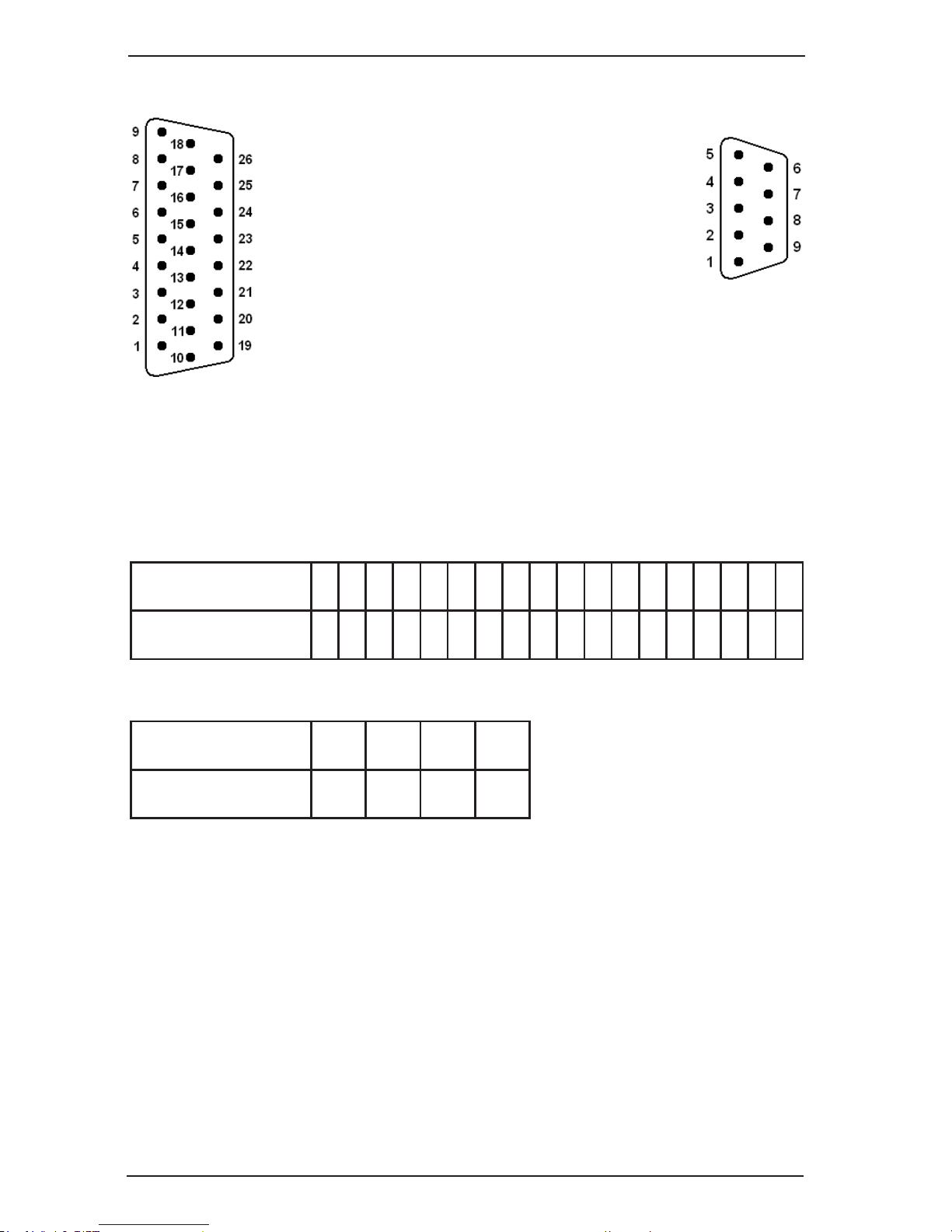
2. Connect alarm sensor to pin Nr.1 on MBRio panel. MBRio pins numeration is
shown in the diagram 1.
Connect relay to Nr.3 and Nr.8 pins on the MBRio panel. Pins
numeration is shown in the diagram 2.
3. Plug the cards into appropriate computer mother
board slots.
4. Connect power cable to connector (3) on
MBRio panel.
Now you should set up parameters of VideoNet
system conguration.
5. Add PowerVN4 Pro2 video capture card to
VideoNet system conguration.
6. Open the properties page of PowerVN4 Pro2 card. Switch to
Card tab. In connecting devices eld specify what type of MBRio
panel you want to use for working with alarm sensors and relay
outputs: MBRio 4/16. It is MBRio panel in our example (see picture 3.1.1-3).
After that you should begin with parameters setup of alarm sensors and relay
outputs on Sensors and Relay output tabs. It is strongly recommended to use
numeration correspondence tables for sensors pins (table 1) and relays (table
2) on MBRio panel and on PowerVN4 Pro2 card (and in VideoNet system)
for correct setup.
Table 1. Numeration correspondence for sensors pins on MBRio panel and on PowerVN4
Pro2 card.
Diagram 1
Table 2. Numeration correspondence for relays pins on MBRio panel and on PowerVN4
Pro2 card.
7. Add the sensor to the system conguration and connect it to the corresponding
input of the MBRio panel in the device tree. The system will start polling the
sensor.
In the example above, the sensor is physically connected to the connection #1
on the MBRio panel which corresponds to the input #2 on the PowerVN4 Pro2
video capture card (refer to the table 1). So, in conguration the sensor must
be added to the input #2. Open the sensor properties, and on the General tab
set the sensor type to Normally open or to Normally closed. You must also
specify minimum closing/opening time for the sensor in the Reaction time eld.
8. Add relays to relay outputs. On the General tab of the relay properties page,
you can specify the relay name and set the ag «Add the relay management
button to the control panel» that will enable relay management from the
management panel of the Surveillance environment.
Diagram 2
sensor Nr. on
PowerVN4 Pro2 card
1 2 3 4 5 6 7 8 9 10 11 12 13 14 15 16
- -
pin Nr. on MBRio
card
19 1 20 2 21 3 22 4 23 5 24 6 25 7 26 8 9 18
relay Nr. on
PowerVN4 Pro2 card
1 2 3 4
pin Nr. on
MBRio card
1 6 2 7 3 8 4 9
15
Installation manual
SKYROS Corporation VideoNet 9.1
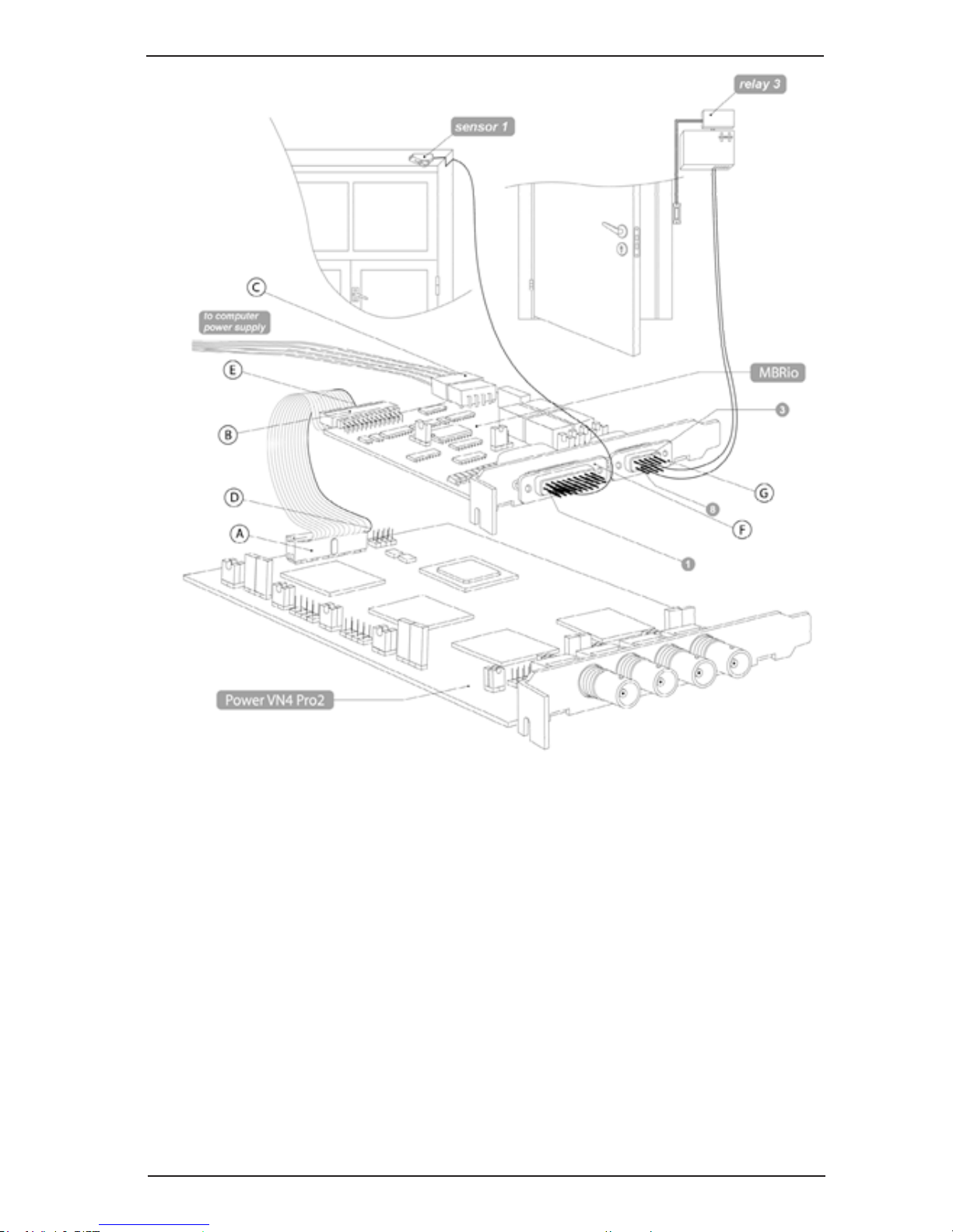
Picture 3.1.1-3. Connecting sensors and relays to inputs of PowerVN4 Pro2 card.
On the picture 3.1.2-3 there are letters:
A. connector for alarm sensors and relay outputs
connection to PowerVN4 Pro2 card
B. connector for alarm sensors and relay outputs
connection to MBRio panel
C. connector for power supply connection
D. rst pin on connector of PowerVN4 Pro2 card
E. rst pin on connector of MBRio panel
F. inputs for alarm sensors connection
G. inputs for relay connection
In the example above the relay is physically connected to contacts #3 and #8
on the MBRio panel which corresponds to the input #3 on the PowerVN4 Pro2
(refer to the table 2). So, in conguration select the Relay 3 in the device tree
and set the ag «Add the relay management button to the control panel».
The detailed description of device connection and conguration can be found
in the User guide, 3.1 section.
SKYROS Corporation VideoNet 9.1
16
Installation manual
3.1.2. PowerVN4 Pro3 video/audio capture card
PowerVN4 Pro3 card is a video/audio capture device, intended for digital capture
of audio and video signals, received from cameras and microphones, connected to
it. Also the card is a sensors controller and a relay outputs controller, and thereby
enables to control sensors and relay outputs, connected to its inputs.
Cameras, transmitting composite signal or signal in S-Video format, are to be
connected to video inputs. Microphones are to be connected to audio inputs.
Connecting relays and sensors to corresponding card outputs/inputs is performed
through additional panels MBRio.
The card consists of four independent CX23880 devices, intended for digital capture
of audio and video signals. Each device can work independently both in the switchable
mode (12 fps) and in the non-switchable mode (25 fps). Thus, maximum frame ow
for a card is 100 fps.
On the card there are:
• 4 main video inputs for working with composite video signal in the real-time
mode (16 additional video inputs for working with composite video signal in the
multiplexing mode);
• 4 inputs for working with colour-difference component and with brightness
component of S-Video signal;
• 8 inputs for working with audio signal;
• 4 relay outputs and 16 alarm sensors inputs.
PowerVN4 Pro3 card must be installed into the PCI Express x1/x4/x8/x16 slot of
motherboard of your computer.
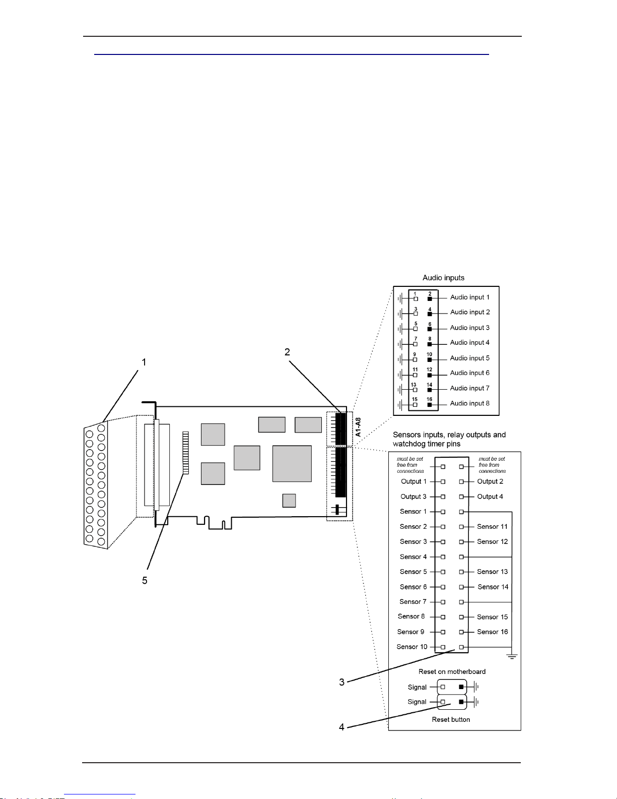
The card diagram is shown in the picture 3.1.2:
•main (1) and additional pin connectors for composite video signal (2) and for
S-Video signal (3);
•jumpers for switching on/off 75 Ohm load (4);
•audio inputs (5)
•connectors for sensors and relay outputs (6);
•LEDs pins (7);
•Watchdog timer pins (8).
PowerVN4 Pro3 card supports working both with S-Video signal and with composite
signal.
For composite signal inputs 1-4 are used in the non-switchable mode and inputs
1-16 are used in the switchable mode.
For working with S-Video signal S1-S4 video
inputs are used for colour-difference component
(S-Video chroma) and 14, 11, 8, 5 video inputs
are used for brightness component (S-Video
luma). When connecting it is necessary to use
an additional video inputs panel for working
with S-Video signal.
Attention! CX23880 chip, working in S-Video
mode, can’t simultaneously work with composite
signal.
For working with audio signal A1–A8 inputs are used.
There are 4 video inputs on each CX23880 device on the PowerVN4 Pro3 card.
17
Installation manual
SKYROS Corporation VideoNet 9.1
Picture 3.1.2. PowerVN4 Pro3 card connectors location.
Use if necessary additional MB-BNC4 and MBDB-25 panels for video signals
connection or additional MB-RCA4 and MBDB-25 panels for audio signals
connection.
Use additional MB-RIO 4/16 units for working with alarm sensors and relay
outputs.
Correspondence between inputs numeration on the card and in the VideoNet system
is shown in the table below:
CX2388х device number
1
2
3
4
Video inputs numeration
4, 5, 6, 7
3, 8, 9, 10
2, 11, 12, 13
1, 14, 15, 16
Audio inputs numeration
1, 2
3, 4
5, 6
7, 8
SKYROS Corporation VideoNet 9.1
18
Installation manual
3.1.3. PowerVN4 Pro4 video/audio capture card
PowerVN4 Pro4 card is a video/audio capture device, intended for digital capture
of audio and video signals, received from cameras and microphones, connected to
it. Also the card is a sensors controller and a relay outputs controller, and thereby
enables to control sensors and relay outputs, connected to its inputs.
Cameras, transmitting composite signal or signal in S-Video format, are to be
connected to video inputs. Microphones are to be connected to audio inputs.
Connecting relays and sensors to corresponding card outputs/inputs is performed
through additional panels MBRio.
The card consists of four independent CX23880 devices, intended for digital capture
of audio and video signals. Each device can work independently both in the switchable
mode (12 fps) and in the non-switchable mode (25 fps). Thus, maximum frame ow
for a card is 100 fps.
On the card there are:
• 4 main video inputs for working with composite video signal in the real-time mode;
• 12 additional video inputs for working with composite video signal in the
multiplexing mode (these inputs can be used for working with brightness
component of S-Video signal);
• 4 inputs for working with colour-difference component of S-Video signal;
• 8 inputs for working with audio signal;
• 4 relay outputs and 16 alarm sensors inputs.
PowerVN4 Pro4 card must be installed into the PCI slot of motherboard of your
computer.
The card diagram is shown in the picture 3.1.3:
•main (1) and additional pin connectors for composite video signal (2) and for
S-Video signal (3);
•jumpers for switching on/off 75 Ohm load (4);
•audio inputs (5)
•connectors for sensors and relay outputs (6);
•LEDs pins (7);
•Watchdog timer pins (8).
PowerVN4 Pro4 card supports working both with S-Video signal and with composite
signal.
For composite signal inputs 1-4 are used in the non-switchable mode and inputs
5-16 are used in the switchable mode (see picture 3.1.3).
For working with S-Video signal S1-S4 video inputs are used for colour-difference
component (S-Video chroma) and
appropriate 14, 11, 8, 5 video inputs are
used for brightness component (S-Video
luma). When connecting it is necessary
to use an additional video inputs panel
for working with S-Video signal.
Attention! CX23880 chip, working in
S-Video mode, can’t simultaneously work
with composite signal.
For working with audio signal A1–A8
inputs are used.
19
Installation manual
SKYROS Corporation VideoNet 9.1
Picture 3.1.3. PowerVN4 Pro4 card connectors location.
Use additional MB-RIO 4/16 units for working with alarm sensors and relay
outputs.
There are 4 video inputs on each CX23880 device on the PowerVN4 Pro4 card.
Correspondence between inputs numeration on the card and in the VideoNet system
is shown in the table below:
Use if necessary additional MB-BNC4 and MBDB-25 panels for video signals
connection or additional MB-RCA4 and MBDB-25 panels for audio signals
connection.
CX2388х device number
1
2
3
4
Video inputs numeration
4, 5, 6, 7
3, 8, 9, 10
2, 11, 12, 13
1, 14, 15, 16
Audio inputs numeration
1, 2
3, 4
5, 6
7, 8

SKYROS Corporation VideoNet 9.1
20
Installation manual
3.1.4. PowerVN4-AHDM video/audio capture card
1
PowerVN4-AHDM card is a video/audio capture device, intended for receiving
digital capture of audio and video signals, received from high-resolution digital video
cameras with analog signal transmission cameras and microphones, connected to it.
The card consists of one NVP6114 device, intended for digital capture of audio and
video signals. Maximum frame ow for the card is 100 fps when working with four
inputs (without external switch).
PowerVN4-AHDM card must be installed into the PCI Express х1/x4/х8/х16 slot
of motherboard of your computer.
On the card there are:
• 4 video inputs for working with composite video signal;
• 4 inputs for working with audio signal.
The card diagram is shown in the picture 3.1.4:
• main (1) pin connectors for composite video and audio signal.
Picture 3.1.4. PowerVN4-AHDM card connectors location.
Cameras and microphones are connected to the video capture card using a special
cable.
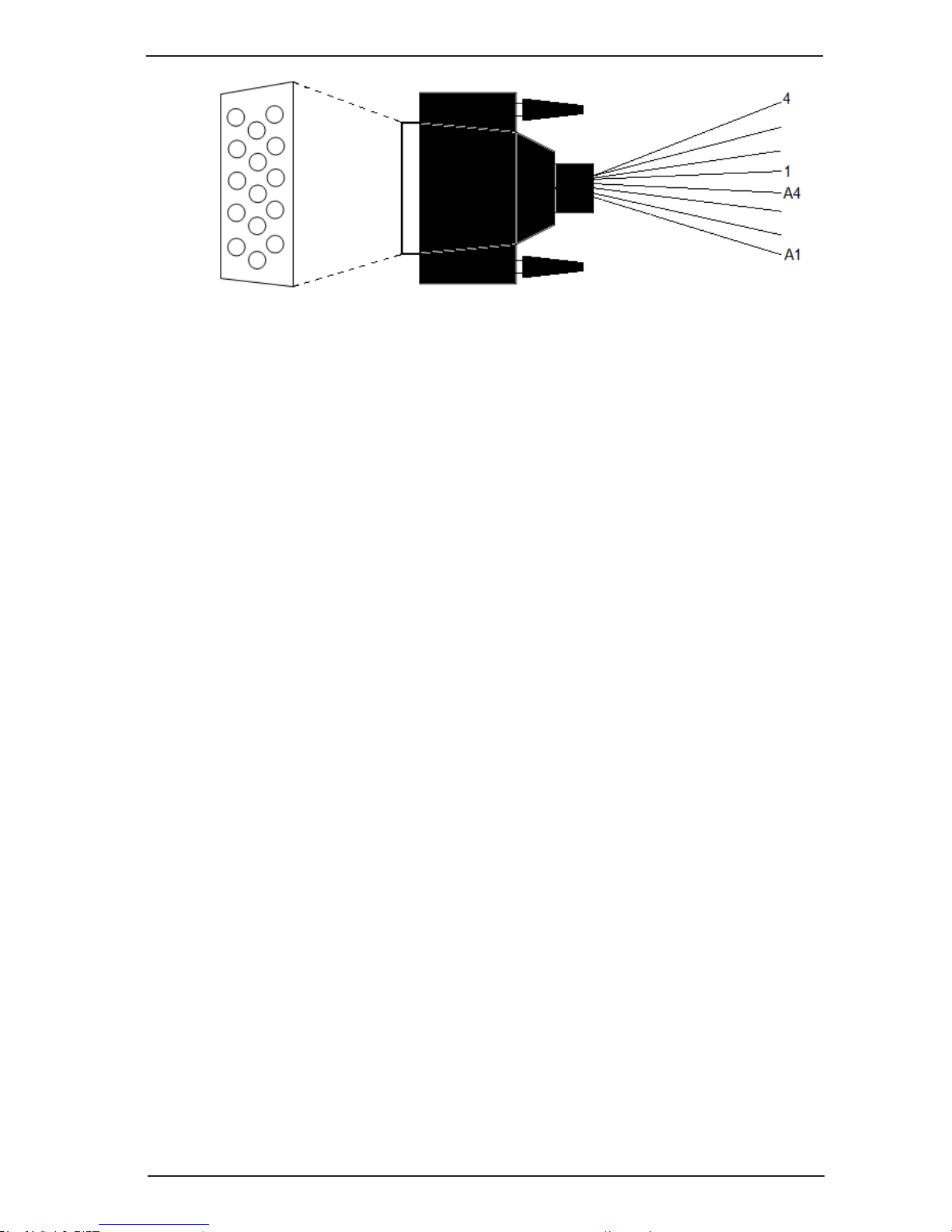
The cable diagram is shown in the picture 3.1.4-1:
• 4 main video inputs for working with composite video signal;
• 4 inputs for working with audio signal.
For composite signal inputs 1-4 are used. For working with audio signal A1–A4
audio inputs are used.
21
Installation manual
SKYROS Corporation VideoNet 9.1
Picture 3.1.4-1. Cable splitter for connecting cameras to PowerVN4-AHDM card.
SKYROS Corporation VideoNet 9.1
22
Installation manual
3.1.5. PowerVN8 / PowerVN8 LP video/audio capture card
PowerVN8 / PowerVN8 LP card is a video/audio capture device, intended for
digital capture of audio and video signals, received from cameras and microphones,
connected to it. Also the card is a sensors controller and a relay outputs controller,
and thereby enables to control sensors and relay outputs, connected to its inputs.
Cameras, transmitting composite signal or signal in S-Video format, are to be
connected to video inputs. Microphones are to be connected to audio inputs.
Connecting relays and sensors to corresponding card outputs/inputs is performed
through additional panel MBRio.
On the card there are:
• 8 main video inputs for working with composite video signal in the real-time mode;
• 8 additional video inputs for working with composite video signal in the multiplexing
mode;
• 8 inputs for working with audio signal;
• 4 relay outputs and 16 alarm sensors inputs.
Picture 3.1.5. PowerVN8 card connectors location.
 Loading...