

Page 1
Professional Charger
Discharger
SkyRC Technology Co., Ltd. 2011
Dual OutputDual Output
Version 1.0
Page 2

TABLE OF CONTENTS
Introduction......................................................................................................................................02
Special features..............................................................................................................................04
Warning and safety notes..............................................................................................................07
Program flow chart........................................................................................................................10
Lithium polymer balance charge program connection diagram..................................................11
Initial parameter setup (users set up)...........................................................................................13
Lithium battery (LiIon/LiPo/LiFe) program
Charging lithium battery in the charge mode...............................................................................16
Charging lithium battery in the balance mode.............................................................................17
Charging lithium battery in the fast charge mode........................................................................18
Charging lithium battery in the s mode ................. .......19
Discharging of lithium battery........................................................................................................19
Charging NiCd/NiMH battery in the charge mode .....................
Discharge of NiCd/NiMH battery..................................................................................................21
Charge/discharge and discharge/charge cycle of NiCd/NiMH battery.... 21
Charging Pb (lead-acid) battery in the charge mode..................................................................22
Discharging of the Pb battery.......................................................................................................22
Storage data program..................................................................................................................23
Load data program.......................................................................................................................24
Various information in the program.............................................................................................24
Warning and error message........................................................................................................25
Recommended accessories........................................................................................................26
Conformity declaration.................................................................................................................27
Maximum circuit power chart.......................................................................................................28
Specification..................................................................................................................................29
Commonly used terms.................................................................................................................30
Warranty and service....................................................................................................................30
torage ................................................. ....
....................................................................................15
................................................. 20
..................................
· 01
Ultimate 200W×2
Page 3
INTRODUCTION
Congratulations on your choice of the Ultim digital intelligent charger from
SKYRC Technology Co., Ltd. You are now the owner of a professional charger/discharger
with battery management and integral balancer.
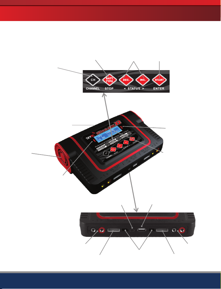
Type/Stop Button
Select Button,
Output1/2
DC input 12V~18V
Temperature
Controlled Fan
Output 1 LED
ate 200W×2
INC/DEC
Button
Membrane
Button System
Enter/Start
Button
Output 2 LED
LCD Screen
Ultimate 200W×2
Charger
Output 1
PC Link Socket USB Power Supply 5V/1A
Balancing Port
Temperature
Sensor
Balancing Port
Charger
Output 2
02 ·
Page 4

INTRODUCTION
Please read this entire operating manual completely and attentively before using this
product, as it covers a wide range of information on operating and safety. Or please do
use this product in company with a specialist!
This unit is simple to use, but the operation of a sophisticated automatic
charger/discharger such as the Ultimate 200W×2 does require some knowledge on the
part of the user. These operating instructions are designed to ensure that you quickly
become familiar with its functions.
It is therefore important that you read right through the Instruction Manual, Warning and
Safety Notes before you attempt to use your new automatic charger for the first time. We
hope you have many years of pleasure and success with your new battery charger.
Ultimate 200W×2 employs the circuit that features dual output power of 200 watts each.
Total output power are 400 Watts. Each output can charge or discharge up 15 cells of
NiCd/NiMH or 6 series of Lithium batteries with maximum current of 10A. Ultimate
200W×2 has an individual cell voltage balancer, so it does not required any balancer
separately when charging Lithium batteries (LiPo/LiIon/LiFe) for voltage balancing.
More reliable/durable membrane button systems are using for charger controls. The fan
cooling system is so smart and efficiently. The fan speed is controlled by internal
temperature sensor.
Please BE SURE to read these instructions and Warning and Safety Notes before you use the
charger for the first time.
It can be dangerous to mishandle batteries and battery chargers, as there is always a risk of
batteries catching fire and exploding.
· 03
Ultimate 200W×2
Page 5

Set contents
2
SPECIAL FEATURES
1
3
4
1. Ultimate 200W×2 Charger
2. XH Adaptor x 2Sets
3. Crocodile Clip Charging Cable
4. 18AWG Wire Charging Cable x 2Pcs
5. Plug-in Battery Clamps
5
Special features
Optimized operating software
Ultimate 200W×2 features the so-called AUTO function that set the feeding current during
the process of charging or discharging. Especially for Lithium batteries, it can prevent the
overcharging which may lead to an explosion due to the user's fault. It can disconnect the
circuit automatically and alarm once detecting any malfunction. All the programs of this
product were controlled through two way linkage and communication, to achieve the
maximum safety and minimize the trouble. All the settings can be configured by users!
Internal independent lithium battery balancer
Ultimate 200W×2 employs an individual-cell-voltage balancer. It isn’t necessary to
connect an external balancer for balance charging.
Balancing individual cells battery discharging
During the process of discharging, Ultimate 200W×2 can monitor and balance each cell
of the battery individually. Error message will be indicated and the process will be ended
automatically if the voltage of any single one cell is abnormal.
Ultimate 200W×2
04 ·
Page 6

SPECIAL FEATURES
Adaptable to various type of lithium battery
Ultimate 200W×2 is adaptable to various types of lithium batteries, such as Li-Ion, LiPo
and the new LiFe series of batteries.
Fast and storage mode of lithium battery
Purposes to charge Lithium battery varies, fast charge reduce the duration of charging,
whereas store state can control the final voltage of your battery, so as to store for a long
time and protect useful time of the battery.
Maximum safety
Delta-peak sensitivity: The automatic charge termination program based on the principle
of the Delta-peak voltage detection. When the battery's voltage exceeds the threshold,
the process will be terminated automatically.
Automatic charging current limit
You can set up the upper limit of the charging current when charging your NiCd or NiMH
battery; it is useful for the NiMH battery of low impedance and capacity in the 'AUTO'
charging mode.
Capacity limit
The charging capacity is always calculated as the charging current multiplied by time. If
the charging capacity exceeds the limit, the process will be terminated automatically
when you set the maximum value.
Temperature threshold
The batteries internal chemical reaction will cause the temperature of the battery to rise.
If the temperature limit is reached, the process will be terminated. This function is
available by connecting temperature probe, which is included in the package.
Processing time limit:
You can also limit the maximum process time to avoid any possible defect.
Data store/load
For user’s convenience, it can store maximum 10 data of different batteries. You can
establish the data contains program setting of the battery to charge or discharge. These
data can be called back at any time you need and the process can be executed without
program setting.
Cyclic charging/discharging
1 to 5 cyclic and continuous process of charge>discharge or discharge>charge is
operable for battery refreshing and balancing to stimulate the batteries activity.
· 05
Ultimate 200W×2
Page 7
SPECIAL FEATURES
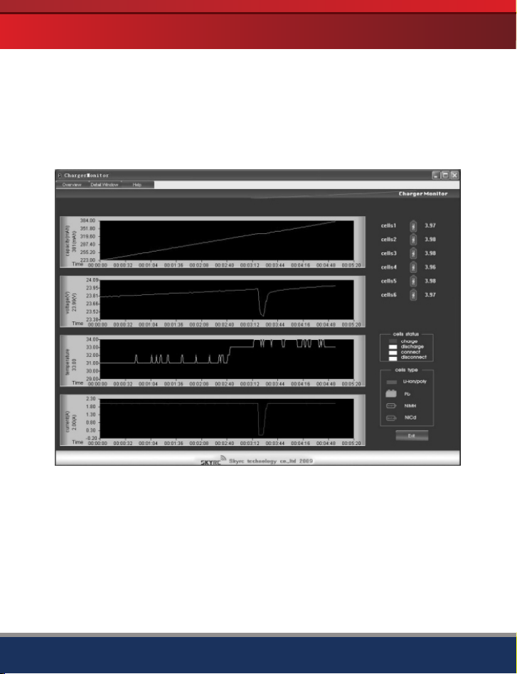
PC based analysis using USB Communication (For output 1 only.)
The Ultimate 200W×2 is fitted with a mini USB port on the front side of the case; a USB
cable(not included) can be connected to this socket in order to link the charger to a PC.
“Charger Monitor” program enable you to view graphs of charge and discharge curves,
with a capacity, voltage, temperature and ampere display, and individual curves can be
individually suppressed or superimposed to allow a visual comparison of the data.
“Charger Monitor” software can be downloaded from our website.
PC Based Analysis Software “Charger Monitor”
USB Power Supply
The USB power supply can provide 5V, 1A continue current. You can power your mobile
phone, digital camera or even iPod via the USB power supply.
Ultimate 200W×2
06 ·
Page 8

WARNING AND SAFETY NOTES
These warnings and safety notes are particularly important. Please follow the
instructions for maximum safety; otherwise the charger and the battery can be
damaged or at worst it can cause a fire.
Never leave the charger unattended when it is connected to its power supply. If any
malfunction is found, TERMINATE THE PROCESS AT ONCE and refer to the
operation manual.
Keep the charger well away from dust, damp, rain, heat, direct sunshine and .
vibration
Never drop it.
The allowable input voltage is 12~18V DC
This charger and the battery should be put on a heat-resistant, noninflammable and
nonconductive surface. Never place them on a car seat, carpet or similar. Keep all
the inflammable volatile materials away from operating area.
Make sure you know the specifications of the battery to be charged or discharged to
ensure it meets the requirements of this charger. If the program is set up incorrectly,
the battery and charger may be damaged .It can cause fire or explosion due to
overcharging. This warranty is not valid for any damage or subsequent damage
arising as a result of a misuse or failure to observe the procedures outlined in this
manual.
Standard Battery Parameters
Nominal
Voltage
Max Charge
Voltage
Storage
Voltage
Allowable
Fast Charge
Min. Discharge
Voltage
LiPo
3.7V/cell
4.2V/cell
3.8V/cell
≦1C
≧3.0V/cell
LiIon
3.6V/cell
4.1V/cell
3.7V/cell
≦1C
≧2.5V/cell
LiFe
3.3V/cell
3.6V/cell
3.3V/cell
≦4C
≧2.0V/cell
NiCd
1.2V/cell
1.5V/cell
n/a
1C-2C
≧0.85V/cell
MiMH
1.2V/cell
1.5V/cell
n/a
1C-2C
≧1.0V/cell
Pb
2.0V/cell
2.46V/cell
n/a
≦0.4C
≧1.75V/cell
Be very careful to choose the correct voltage for different types of battery otherwise you
may cause damage to the batteries. Incorrect settings could cause the cells to fire or
explode.
· 07
Ultimate 200W×2
Page 9

WARNING AND SAFETY NOTES
Never attempt to charge or discharge the following types of batteries.
A battery pack which consists of different types of cells (including different
manufacturers)
A battery that is already fully charged or just slightly discharged.
Non-rechargeable batteries (Explosion hazard).
Batteries that require a different charge technique from NiCd, NiMh, LiPo or Gel cell
(Pb, Lead acid).
A faulty or damaged battery.
A battery fitted with an integral charge circuit or a protection circuit.
Batteries installed in a device or which are electrically linked to other components.
Batteries that are not expressly stated by the manufacturer to be suitable for the
currents the charger delivers during the charge process.
Please bear in mind the following points before commencing charging:
Did you select the appropriate program suitable for the type of battery you are
charging?
Did you set up adequate current for charging or discharging?
Have you checked the battery voltage? Lithium battery packs can be wired in parallel
and in series, i.e. a 2 cell pack can be 3.7V (in parallel) or 7.4V (in series).
Have you checked that all connections are firm and secure?
Make sure there are no intermittent contacts at any point in the circuit.
Charging
During charge process, a specific quantity of electrical energy is fed into the
battery. The charge quantity is calculated by multiplying charge current by charge
time. The maximum permissible charge current varies depending on the battery
type or its performance, and can be found in the information by the battery
manufacturer. Only batteries that are expressly stated to be capable of quickcharge are allowed to be charged at rates higher than the standard charge current.
Connect the battery to the terminal of the charger: red is positive and black is
negative. Due to the difference between resistance of cable and connector, the
charger can not detect resistance of the battery pack, the essential requirement
for the charger to work properly is that the charge lead should be of adequate
conductor cross-section, and high quality connectors which are normally goldplated should be fitted to both ends.
Always refer to the manual by the battery manufacturer pertaining to charging
methods, recommended charging current and charging time. Especially, the
Lithium battery should be charged according the charging instruction provided
by the manufacturer strictly.
Ultimate 200W×2
08 ·
Page 10

WARNING AND SAFETY NOTES
Attention should be paid to the connection of Lithium battery especially.
Do not attempt to disassemble the battery pack arbitrarily.
Please get highlighted that Lithium battery packs can be wired in parallel and in
series. In the parallel connection, the battery s capacity is calculated by multiplying
single battery capacity by the number of cells with total voltage stay the same. The
voltages imbalance may cause fire or explosion .Lithium battery is recommended to
charge in series.
Discharging
The main purpose of discharging is to clean residual capacity of the battery, or to
reduce the battery voltage to a defined level. The same attention should be paid to
the discharging process as charging. The final discharge voltage should be set up
correctly to avoid deep-discharging. Lithium battery can not be discharged to lower
than the minimum voltage, or it will cause a rapid loss of capacity or a total failure.
Generally, Lithium battery doesn't need to be discharged. Please pay attention to the
minimum voltage of Lithium battery to protect the battery.
Some rechargeable batteries have a memory effect. If they are partly used and
recharged before the whole charge is accomplished, they remember this and will only
use that part of their capacity next time. This is a memory effect It is said that NiCd
and NiMH batteries are suffering from memory effect. NiCd has more memory effect
than NiMH.
Lithium batteries are recommended to be discharged partially rather than fully
discharged. Frequent full discharging should be avoided if possible. Instead, charge
the battery more often or use a battery of larger capacity. Full capacity cannot be
reached until it has been subjected to 10 or more charge cycles. The cyclic process
of charge and discharge will optimize the capacity of battery pack.
· 09
Ultimate 200W×2
Page 11

PROGRAM FLOW CHART
Ultimate 200W×2
10 ·
Page 12

LITHIUM POLYMER BALANCE CHARGE PROGRAM
CONNECTION DIAGRAM
CONNECTING THE CHARGER
Ultimate 200W×2 comes with male 4mm Bullet connectors attached to the power INPUT
cables. These cables are appropriate for attaching directly to most high-quality AC-DC
power supply units, such as eFUEL model PSU30A (15V, 30A). Also included are large
Terminal Clips with matching 4mm female bullet connectors, for attaching directly to 12V
car batteries. It is critically important that you use either a fully charged 13.8 car battery or
a high quality AC-DC power supply in the range of 12V to18V DC output, with minimum
current rating of 30A to insure reliable performance.
4mm Bullet
Connectors
plugging
to eFUEL power
supply directly
Important Notice
To take advantage of Ultimate 200W×2’s full power capability,
the power source should be 15V-18V DC, and output power
should be capable of 500W or higher.
Low quality DC power source may damage your Ultimate
200W×2 charger. We recommend you to choose our
PSU30A, 540W DC power supply.
Using terminal
clip attaching to
car battery
CONNECTING THE BATTERY
Important !!! Before connecting a battery it is absolutely essential to check one last time
that you have set the parameters correctly. If the settings are incorrect, the battery may
be damaged, and could even burst into flames or explode. To avoid short-circuits
between the banana plugs, always connect the charge leads to the charger first, and only
then to the battery. Reverse the sequence when disconnecting the pack.
· 11
Ultimate 200W×2
Page 13

LITHIUM POLYMER BALANCE CHARGE PROGRAM
CONNECTION DIAGRAM
Balance socket:
The balance wire attached to the battery must be connected to the charger balancing
port. Take care to maintain correct polarity!
(Wiring diagram: see below.)
This diagram shows the correct way to connect your battery to the Ultimate 200W×2
while charging in the balance charge program mode only.
WARNING:
Failure to connect as shown in this diagram will damage this charger.
To avoid short circuit between the charge lead always connect the charge cable to the
charger first, then connect the battery. Reverse the sequence when disconnecting.
Ultimate 200W×2
12 ·
Page 14

INITIAL PARAMETER SETUP (USERS SET UP)
Initial parameter set up (Users set up)
Ultimate 200W×2 will be operated with the default value of the essential user settings
when it is connected to a 12V battery for the first time. The screen displays the following
information in sequence and the user can change the value of parameter on each screen.
When you are willing to alter the parameter value in the program, press start/enter key to
make it blink then change the value with Inc> or <Dec key. The value will be stored by
pressing start/enter key once.
User set up starting screen.
IN C
DE C INC
IN CDE C
IN CDE C
DE C
IN C
IN CDE C
DE C
IN C
The screen displays the nominal voltage of Lithium battery. There
are three kinds of Lithium battery: LiFe(3.3V), Lilo(3.6V) or LiPo
(3.7V). This is very important so you have to check the battery
carefully and set it up correctly. If it is different from correct value
the battery may be exploded during charge process.
Ultimate 200W×2 recognize the cell count of Lithium battery
automatically at the beginning of charge or discharge process to
avoid from erroneous setting by user. But deeply discharged
battery can be perceived incorrectly. To prevent the error, you can
set the time term to verify the cell count by the processor. Normally,
10 minutes are enough to perceive the cell count correctly. For the
battery of larger capacity, you may extend the time term. But if you
set the time term too long for the battery of smaller capacity, the
charge or discharge process can be finished within the time term
with the erroneous cell count. This may cause the fatal result. If the
processor recognizes the cell count incorrectly at the beginning of
charge or discharge process, you may extend the time. Otherwise,
you had better use with the default value.
Termination of NiMH and NiCd battery, the effective value ranges
from 5 to 20mV per cell. If the trigger voltage is set higher, there is
a danger of over charging the battery; if it is set lower, there is a
possibility of premature termination. Please refer the technical
specification of the battery. (NiCd default: 12mV, NiMH default:
7mV)
· 13
Ultimate 200W×2
Page 15

INITIAL PARAMETER SETUP (USERS SET UP)
DE C I NC
DE C
DE C
IN C
DE C
IN C
IN C
IN CDE C
DE C I NC
DE C
DE C
IN CD EC
DE C
IN CDE C
DE C
IN CDE C
DE C
IN CDE C
DE C
IN CDE C
An optional feature using temperature probe contacting the
surface of battery, the temperature cut-off can be on or off. If it is
on, set the maximum temperature at which the charger should
allow battery to reach during charge. Once a battery reaches this
temperature during charge, the process will be terminated to
protect the battery.
The battery is on the cyclic process of charge and discharge can
often become warm after charge or discharge period. The
program can insert a time delay to occur after each charge and
discharge process to allow the battery adequate time to cool
IN C
down before being subjected to the next process. The value
ranges from 1 to 60 minutes.
You can set the trickle charge mode on or off. If it is on, the
charger will automatically supply the trickle charge current to
achieve the full charge without overheating the battery after fast
charge has been terminated.
IN C
When you start a charge process, the integral safety timer
automatically starts running at the same time. This is
programmed to prevent overcharge the battery if it proves to be
faulty, or if the termination circuit cannot detect the battery full.
IN C
The value for the safety timer should be generous enough to
allow a full charge of the battery.
This program sets the maximum charge capacity that will be
supplied to the battery during charge. If the delta-peak voltage is
not detected nor the safety timer expired by any reason, this
feature will automatically stop the process at the selected
IN C
capacity value.
The beep sounds at every time pressing the buttons to confirm
your action. The beep or melody sounded at various times during
operation to alert different mode changes. These audible sounds
can be turned on or off.
IN C
This program monitors the voltage of input battery. If the voltage
drops below the value you set the operation forcibly terminated to
protect the input battery.
IN C
You can adjust the brightness of LCD screen at the charger.
DE C
Ultimate 200W×2
IN C
14 ·
Page 16

LITHIUM BATTERY (LIION/LIPO/LIFE) PROGRAM
Lithium battery (LiIon/LiPo/LiFe) program
These programs are only suitable for charging and discharging Lithium batteries with a
nominal voltage of 3.3V, 3.6V and 3.7V per cell. These batteries need to adopt different
charge technique that is termed constant current (CC) and a constant voltage (CV)
method. The charge current varies according to the battery capacity and performance.
The Lithium battery is charged at a
constant current until it reaches the final
charge voltage of 4.2 V per cell (B).
V/A /Ah
V
A
4.2 V
After this point the voltage is kept at a
constant level, and the residual charge
takes the form of a declining current
Ah
curve (C) until the cut-off point (D) is
reached. Charge current = C/10. At this
point the battery can be disconnected
from the charger, and is ready for use.
A
B
C
D
t
The final voltage of charge process is also very important; it should be precisely matched
with the charged voltage of the battery. They are 4.2V for LiPo, 4.1V for Lilo, and 3.6V for
LiFe. The charge current and nominal voltage as for cell count set on the charge program
must always be correct for the battery to be charged.
When you are willing to alter the parameter value in the program, press start/enter key to
make it blink then change the value with Inc> or <Dec key. The value will be stored by
pressing start/enter key once.
· 15
Ultimate 200W×2
Page 17

CHARGING LITHIUM BATTERY IN THE CHARGE MODE
Charging lithium battery in the charge mode
This charging mode is for charging Li-Po/Ion/Fe battery without balance lead.
The left side of the first line shows the type of battery you
choose. The value on the left of the second line of the
charger is current user set. After setting the current and
+
voltage, press Start/Enter key for more than 3 seconds to
INC
start the process.(charge current: 0.1-10.0A, voltage: 3.7-
22.2V).
This displays the number of cells you set up and the
processor detects. R shows the number of cells detected by
the charger and S is the number of cells set by you at the
previous screen. If both numbers are identical you can start
charging by press Start/Enter button. If not, press Batt
Type/Stop button to go back to previous screen to carefully
check the number of cells of the battery pack before going
ahead.
This screen shows the real-time status during charge
process. Press Batt Type/Stop key once to stop the charge
process.
Cha rged
cap acity
DE C
Num ber
of
cel ls
-
Bat t type
Sto p
+
INC
Cha rging
tim e
Sta rt
Ent er
Cha rging
cur rent
DEC
Sta rt
Ent er
Bat tery
vol tage
-
'> 3 seconds '
Ultimate 200W×2
16 ·
Page 18

CHARGING LITHIUM BATTERY IN THE BALANCE MODE
Charging lithium battery in the balance mode
This function is for balancing the voltage of Lithium-polymer battery cells while charging.
In the balance mode, the battery needs to have a balance lead to connect to the
individual balance port of the charger. And you need to connect the battery's power lead
to the output of charger. Charging in this mode is different from the normal modes,
because the built-in processor monitors voltage of individual cell and control input current
fed into each cell to equalized voltage of individual cell.
The left side of the first line shows the type of battery you
choose. The value on the left of the second line of the
charger is current user set. After setting the current and
DEC
Num ber
of
cel ls
-
+
Bat t type
Sto p
Cha rging
tim e
INC
Sta rt
Ent er
Cha rging
cur rent
-
DEC
'> 3 seconds '
Sta rt
Ent er
Bat tery
vol tage
voltage, press Start/Enter key for more than 3 seconds to
+
INC
start the process.(charge current: 0.1-10.0A, voltage: 3.7-
22.2V).
This displays the number of cells you set up and the
processor detects. R shows the number of cells detected by
the charger and S is the number of cells set by you at the
previous screen. If both numbers are identical you can start
charging by press Start/Enter button. If not, press Batt
Type/Stop button to go back to previous screen to carefully
check the number of cells of the battery pack before going
ahead.
This screen shows the real-time status during charge
process. Press Batt Type/Stop key once to stop the charge
process.
Cha rged
cap acity
· 17
Ultimate 200W×2
Page 19

CHARGING LITHIUM BATTERY IN THE FAST CHARGE MODE
Charging lithium battery in the fast charge mode
The charging current is getting smaller as the process goes to the near end term of
Lithium battery charging. To finish charging process earlier, this program eliminate certain
term of CV process. Actually, the charging current will goes to 1/5 from the initial value to
end the process while the normal charging goes to 1/10 during CV term. The charging
capacity may be a bit smaller than normal charging but the process time will be reduced.
The value on the left side of the second lines sets the
charge current. The value on the right side of the second
lines sets the battery pack's voltage. After setting current
and voltage, press Star/Enter for more than 3 seconds to
++
start the process.
INCINC
This displays the number of cells you set up and the
processor detects. R shows the number of cells detected
by the charger and S is the number of cells set by you at
the previous screen. If both numbers are identical you can
start charging by press Start/Enter button. If not, press
Batt Type/Stop button to go back to previous screen to
carefully check the number of cells of the battery pack
before going ahead.
This screen shows the real-time status during charge
process. Press Batt Type/Stop key once to stop the
Cur rent
charge process.
vol tage
bat tery
Num ber
of
cel ls
Bat t type
Sto p
Cha rging
tim e
Cha rge
cur rent
DECDEC
Sta rt
Ent er
Sta rt
Ent er
Sup plied
cap acity
--
'> 3 se conds '
Ultimate 200W×2
18 ·
Page 20

CHARGING LITHIUM BATTERY IN THE STORAGE MODE
Charging lithium battery in the storage mode
This is for charging or discharging Lithium battery not to be used for the time being. The
program will determine to charge or discharge the battery to the certain voltage
depending on the voltage of the battery at its initial stage. They are different from the type
of the battery, 3.75V for LiIo, 3.85V for LiPo and 3.3V for LiFe per cell. If the voltage of
battery at its initial stage is over the voltage level to storage, the program will start to
discharge.
At this screen, you can set up the current and voltage of the
battery pack. Charging and discharging will make the
batteries come to the voltage level of storage state.
-
+
DEC
INC
Bat t type
Sto p
Ela psed
Num ber
tim e
of
cel ls
Discharging of lithium battery
-
+
DEC
INC
Bat t type
Sto p
ela psed
Num ber
tim e
of
dis charg e
cel ls
cur rent
DEC
Sta rt
Ent er
Sup plied
cap acity
Cha rge
or di schar ge
cur rent
-
DEC
Sta rt
Ent er
Bat tery
vol tage
-
+
INC
'> 3 se conds '
Cur rent
vol tage
bat tery
+
INC
'> 3 se conds '
Dis charg ed
cap acity
This screen shows the real-time status charging. Press Batt
Type/Stop key once to stop the charge process.
The value of discharge current on the left can not exceed 1C,
and the value on the right can not be under the voltage
recommended by the manufacturer to avoid deep discharging.
Press Start/Enter for more than 3 seconds to start
discharging.
This shows the real-time status of discharging, you can press
Batt Type/Stop key to stop discharging.
· 19
Ultimate 200W×2
Page 21

CHARGING NICD/NIMH BATTERY IN THE CHARGE MODE
Voltage balancing and monitoring in th e discharge process
The processor monitors voltage of each cell when the battery packs are during its storage
and discharging process. If voltage of any cell is abnormal, Ultimate 200W×2 will show
error message and terminate the program forcibly. So if there is battery damage or
disconnection, you can see the error message and press Inc to know which cell is
damaged.
The processor detects voltage of one cell is too low.
INC
The 4th cell was damaged. The value of voltage may be zero if
disconnection occurs.
Charging NiCd/NiMH battery in the charge mode
This program charge the battery using the current you set up. In the auto state,
you should set up the upper limit of the charge current to avoid damage by excessive
feeding current. Some batteries of low resistance and capacity can lead to higher current
in the auto charging mode. But in the manual mode, it will charge with the current you set.
You can make it blink in the current field and press Inc and Dec simultaneously to swap
between Auto and Manual Mode. AllowableNOTE: fast charge current: 1C-2C
This program is for charging of NiCd/NiMH batteries
associated with R/C models applications. You can press
Start/Enter key to make it blink and then Inc or Dec to
DEC
Bat t type
Sto p
Bat tery
typ e
-
Ela psed
tim e
+
INC
Cha rge
cur rent
Sta rt
Ent er
Bat tery
vol tage
DEC
-
+
'> 3 se conds '
change the parameter value. Press START/ENTER key to
INC
store the value.
The screen shows the real-time status. Press Batt Type/Stop
key to end the program. The sound will emitted to indicates
the end of program.
Cha rged
cap acity
Ultimate 200W×2
20 ·
Page 22

DISCHARGE OF NICD/NIMH BATTERY
Discharge of NiCd/NiMH battery
Set discharge current on the left and the final voltage on the
right. Range of the discharge current is 0.1-5.0A; range of
final voltage is 0.1-25.0V. Press Start/Enter key for more
than 3 seconds to start the program.
+
INC
'> 3 se conds '
The screen indicates the discharging state. You can press
Start/Enter key to alter discharge current. Press Start/Enter
again to store the value. Press Batt Type/Stop key to stop
discharging. The emitted sound alerts the end of discharging.
Dis charg ed
cap acity
You can set up sequence on the left and the number of
cycles on the right. Range of the cycle number is 1-5.
Bat tery
typ e
DEC
-
+
INC
Batt ty pe
Stop
Ela psed
tim e
DEC
Bat tery
vol tage
Dis charg e
cur rent
-
Start
Enter
Charge/discharge and discharge/charge cycle of NiCd/NiMH battery
DEC
Bat tery
typ e
· 21
-
+
INC
Bat t type
Sto p
Ela psed
tim e
Sta rt
Ent er
Bat tery
vol tage
Dis charg e
or ch arge
cur rent
-
+
DEC
'> 3 se conds '
Dis charg ed
or ch arged
cap acity
INC
Press Batt Type/Stop key to stop program, you can press
Start/Enter key to alter charge current. The sound indicates
the end of program.
When it approaches to the end, you can see the capacity of
the battery being charged or discharged. You can press Inc
or Dec key to display result of each cycle.
Ultimate 200W×2
Page 23

CHARGING PB (LEAD-ACID) BATTERY IN THE CHARGE MODE
Charging Pb (lead-acid) battery in the charge mode
This program is only suitable for charging Pb lead-acid battery with nominal
voltage from 2 to 24V. Pb lead-acid battery is completely different from NiCd/NiMH
battery. These batteries can only deliver current lower in comparison to their capacity. The
same restriction applies to the charging process. Consequently, the optimum charge
current can only be 1/10 of the capacity. Pb battery can not be used for fast-charging,
please follow the instructions provided by the battery manufacturer. Due to the chemistry
characteristic of Pb battery, the cut off point may be difficult to detect sometimes. We
recommend user to use CAPACITY CUT OFF feature to protect the battery. You can
press Start/Enter key to make it blink and alter the value of parameters using INC or
DEC key, press Start/Enter key to store the value.
Set up the charge current on the left and nominal voltage on
the right. Range of current is 0.1-10.0A, the voltage should
match the battery being charged. Press Start/Enter key for
more than 3 seconds to start charging.
+
INC
The screen displays the real-time discharging status. Press
Start/Enter key to alter discharge current. Press Start/Enter
key again to store the parameter value you set. Press Batt
Type/Stop key to end the program.
Cha rged
cap acity
Set up the discharge current on the left and nominal voltage
on the right. Range of discharge current is 0.1-5.0A, the
voltage should match the battery being charged. Press
Start/Enter key for more than 3 seconds to start charging.
+
INC
Bat tery
typ e
DEC
-
+
INC
Bat t type
Sto p
Ela psed
tim e
Cha rge
cur rent
DEC
Sta rt
Ent er
Bat tery
vol tage
-
'> 3 se conds '
Discharging of the Pb battery
DEC
-
+
INC
DEC
-
Bat t type
Sto p
Ela psed
Bat tery
tim e
typ e
Dis charg e
cur rent
Ultimate 200W×2
Sta rt
Ent er
Bat tery
vol tage
'> 3 se conds '
The screen displays the real-time discharging status. Press
Start/Enter key to alter discharge current. Press Start/Enter
key again to store the parameter value you set. Press Batt
Type/Stop key to end the program.
Dis charg ed
cap acity
22 ·
Page 24

STORAGE DATA PROGRAM
Storage data program
For your convenience, Ultimate 200W×2 has a data storage and load program. It can
store ten batteries data representing the respective specifications of batteries. You can
call back the data when charging or discharging without setting up the program again.
Press Start/Enter key to make it blink, and use Inc or Dec to set up the parameter.
Sta rt
Volt age
DEC
DE C
-
DEC
Dat a
num ber
Bat t type
sto p
INC
-
+
INC
DEC
+
INC
Ent er
INC
Sta rt
Ent er
Cap acity
Sta rt
'> 3 se conds '
Ent er
-
DEC
-
DEC
-
DEC
'> 3 se conds '
+
Setting of the parameter in the screen will not affect the
charge and discharge process. They just present the
specification of the battery. The example is NiMH battery
pack, including 12 cells, the capacity is 3000m Ah.
Type o f
bat tery
Set up the charge current in the manual mode, or current limit
in the auto mode. Press Inc and Dec key simultaneously to
make the current field blink to switch the charge mode.
INC
Set up the discharge current and final voltage.
+
INC
Set up the charge/ discharge sequence and cycle number.
+
INC
Saving the data
· 23
Ultimate 200W×2
Page 25

LOAD DATA PROGRAM
Load data program
This program is to load the data stored at the save data program. Press Start/Enter key
to make the data field blink and press INC or DEC for more than 3 seconds to load the
data.
Sta rt
Ent er
Choose the data number you want to call back. The data you
want to call back will be displayed.
Sta rt
'> 3 se conds '
Ent er
Loading the data.
Various information in the program
You can inquire various information on the LCD screen during the charging and discharging
process. Press Dec key, the charger will display users' setting. You can press Inc key to
monitor voltage of each cell while the battery balance lead is connected to the charger.
It comes to the final voltage when the program ended.
Displayed capacity cut-off function is turn on and the setting
value of capacity.
Displayed safety timer is turn on and duration of time in minutes.
C 5: 4 . 1 8 C 6 : 4 . 1 5V
C 7: 0 . 0 0 C 8 : 0 . 0 0V
Ultimate 200W×2
Displayed temperature cut-off function is turn on.
The external temperature is displayed when the temperature
probe is used.
Present input voltage.
The battery is connected with balance lead, you can check
voltage of each cell in the battery pack.
24 ·
Page 26

WARNING AND ERROR MESSAGE
Ultimate 200W×2 incorporates a various functions of protective and monitoring the
system to verify functions and the state of its electronics. In any case of occurring error,
the screen displays the cause of error that is self-explanatory with audible sound.
Incorrect polarity connected.
Battery connection is interrupted.
Short-circuit of the output termination.
Input voltage wrong.
The voltage of the battery pack has been selected incorrectly!
The charger has malfunctioned for some reason. Seek professional
advice.
The voltage is lower than which is set. Please check the number of
cells in the battery pack.
The voltage is higher than which is set. Please check the number of
cells in the battery pack.
Voltage of one cell in the battery pack is too low; please check the
voltage of each cell.
Voltage of one cell in the battery pack is too high; please check the
voltage of each cell.
Wrong connection of the connector detected; please check the
connector and cable.
· 25
The internal temperature of the unit goes too high. Cool down the unit.
The processor cannot control the feeding current, please repair it.
Ultimate 200W×2
Page 27

RECOMMENDED ACCESSORIES
DC Power Supply
540W, 30A
TP/FP Adaptor
Glow charging cable
Dean charging cable
Sensor Cable
HP/PQ Adaptor
Bullet charging cable
JST/BEC charging
cable
EH Adaptor
Tamiya charging
cable
XH AdaptorTemperature
TRAXXAS
cable
charging
EC3 charging cable Crocodile clip
charging cable
Futaba RX
charging cable
Ultimate 200W×2
26 ·
Page 28

CONFORMITY DECLARATION
Ultimate 200W×2 satisfy all relevant and mandatory EC directives and FCC Part 15
Subpart B: 2008.
For EC directives:
The product has been tested to meet the following technical standards:
Electromagnetic compatibility (EMC) -- Part 6-3:
EN 61000-6-3:2007
EN 55014-1:2006
EN 61000-6-1:2007
EN 55014-2:1997+
A1:2001+A2:2008
EN 61000-3-2:2006
EN 61000-3-3:1995 +
A1:2001+A2:2005
Generic standards - Emission standard for residential,
commercial and light-industrial environments
Electromagnetic compatibility - Requirements for
household appliances, electric tools and
similar apparatus -- Part 1: Emission
Electromagnetic compatibility (EMC) Part 6-1:
Generic standards Immunity for residential,
commercial and light-industrial environments
Electromagnetic compatibility - Requirements for
household appliances, electric tools and
similar apparatus - Immunity - Product family
standard
Electromagnetic compatibility (EMC) — Part 3-2:
Limits — Limits for harmonic
current emissions (equipment input current ≤ 16 A
per phase)
Electromagnetic compatibility (EMC) — Part 3-3:
Limits — Limitation of voltage
changes, voltage fluctuations and flicker in public
low-voltage supply systems, for equipment
with rated current ≤ 16 A per phase and not subject
to conditional connection
This symbol means that you must dispose of electrical from the General household
waste when it reaches the end of its useful life. Take your charger to your local
waste collection point or recycling centre. This applies to all countries of the
European Union, and to other European countries with a separate waste collection
system.
· 27
Ultimate 200W×2
Page 29

MAXIMUM CIRCUIT POWER CHART
Maximum circuit power chart (Output 1 & 2)
The actual amount of charge current feeding to the battery is automatically be limited to
200 Watts each, so not to exceed the charger's maximum rated charging power. The
maximum discharge power is approximately 25 Watts. The discharge current delivered to
the charger is limited by charger's internal thermal sensor for maximum discharge
current. If the internal temperature over 80 Celsius, the charger will be cut off and "TEMP
OVER ERR" will show on the LCD. In this case, please decrease discharging current.
Please refer following chart for maximum charging/discharging current.
Battery
Type
NiCd/NiMH
Ultimate 200W×2
28 ·
Page 30

MAXIMUM CIRCUIT POWER CHART
Battery
Type
Specification
Operating voltage range
Circuit power
Charge current range
Discharge current range
Current drain for balancing Li-Po/Ion/Fe
Li-ion/Fe/Polymer cell count
NiCd/NiMH battery cell count
Pb battery voltage
Net weight
Dimension
DC 12.0~18.0 Volt
Max. Charge power 2x200Watts
Max. Discharge power 2x25Watts
0.1~10.0A
0.1~5.0A
200mA/cell
1~6cells
1~15cells
2V~20V
740g
200x135x57mm
Liability exclusion
This charger is designed and approved exclusively for use with the types of battery stated
in this Instruction Manual. SkyRC accepts no liability of any kind if the charger is used for
any purpose other than that stated.
We are unable to ensure that you follow the instructions supplied with the charger, and
we have no control over the methods you employ for using, operating and maintaining the
device. For this reason we are obliged to deny all liability for loss, damage or costs which
are incurred due to the incompetent or incorrect use and operation of our products, or
which are connected with such operation in any way.Unless otherwise prescribed by law,
our obligation to pay compensation, regardless of the legal argument employed, is limited
to the invoice value of those SkyRC products which were immediately and directly
involved in the event in which the damage occurred.
· 29
Ultimate 200W×2
Page 31

COMMONLY USED TERMS
Commonly used terms
Final charge voltage: the voltage at which the battery's charge limit (capacity limit) is
reached. The charge process switches from a high current to a low maintenance rate
(trickle charge) at this point. From this point on further high current charging would cause
overheating and eventual terminal damage to the pack.
Final discharge voltage: the voltage at which the battery's discharge limit is reached. The
chemical composition of the batteries determines the level of this voltage. Below this
voltage the battery enters the deep discharge zone. Individual cells within the pack may
become reverse in this condition, and this can cause permanent damage.
A, mA: unit of measurement relating to charge or discharge current.1000 mA = 1 A
(A=Ampere,mA=Milliampere)
Ah, mAh: unit of measurement for the capacity of a battery (Amperes x time unit; h = hour).
If a pack is charged for one hour at a current of 2 A, it has been fed 2 Ah of energy. It
receives the same quantity of charge (2 Ah) if it is charged for 4 hours at 0.5 A, or 15
minutes (=1/4 h) at 8 A.
'C'-rating: Capacity is also referred to as the 'C' rating. Some battery suppliers recommend
charge and discharge currents based on the battery 'C' rating. A battery's '1C' current is the
same number as the battery's rated capacity number, but noted in mA or amps. A 600mAh
battery has a 1C current value of 600mA, and a 3C current value of (3 x 600mA) 1800mA or
1.8A. The 1C current value for a 3200mAh battery would be 3200mA (3.2A).
Nominal voltage(V): The nominal voltage of the battery pack can be determined as follows;
-.NiCd or NiMH: multiply the total number of cells in the pack by 1.2. A 8-cell pack will have a
nominal voltage of 9.6 volts (8x1.2).
-.LiPo: multiply the total number of cells in the pack by 3.7. A 3-cell LiPo wired in series will
have a nominal voltage of 11.1 volts (3x3.7).
-.LiIo: multiply the total number of cells in the pack by 3.6. A 2-cell LiIo wired in series will have
a nominal voltage of 7.2 volts (2x3.6).
-.LiFe: multiply the total number of cells in the pack by 3.3. A 4-cell LiIo wired in series will have
a nominal voltage of 13.2 volts (4x3.3).
If the nominal voltage of the battery is not printed on the battery's label, consult your battery
manufacturer or supplier. Do not guess the rated voltage of battery.
Warranty and service
We guarantee this product to be free of manufacturing and assembly defects for a period
of one year from the time of purchase. The warranty only applies to material or
operational defects, which are present at t he time of purchase. During that period, we will
repair or replace free of service charge for products deemed defective due to those
causes.
You will be required to produce proof of purchase (invoice or receipt). This warranty is not
valid for any damage or subsequent damage arising as a result of misuse, modification or
as a result of failure to observe the procedures outlined in this manual.
polarized
Ultimate 200W×2
30 ·
Page 32

Manufactured by
SKYRC TECHNOLOGY CO., LTD.
www.skyrc.com
All specifications and figures are subject to change without notice.
Printed in China 2011
 Loading...