

Page 1
INSTRUCTION MANUAL
For 1/8 Scale Car
Support Both Sensor or Sensor-less Brushless Motor
INTRODUCTION
Thank you for purchasing TORO 1/8 ESC from SKYRC TECHNOLOGY CO.,LTD. Please
read the Instruction Manual thoroughly before you use the product. These operating
instructions are designed to ensure that you quickly become familiar with its features and
functions and make full use of this product.
FEATURES
Well-performed throttle and brake control function could control the punch/brake rate by
point and the point can be set by user. The precision of the punch/brake rate is 1%. And
the user could also custom the throttle/brake curve.
Punch control is reasonable and precise and it can meet different customers' request for
line and power.
Users could modify the setting, monitor the ESC and motor status at any time by smart
phone via Bluetooth Module (Bluetooth Module adaptor can be purchased separately,
which is not included in the package).
Red copper connector is used internal of the ESC. It can decrease the internal
resistance at high current situation and the thermal resistance.
The circuit is managed by intelligent thermal management kernel algorithm which can
improve driving skill and adjust the control time of the dead band. The dynamic loss can
be reduced effectively when the motor is running at high speed or the user changes the
motor speed frequently so that the motor can be more stable when running.
Heat transfer: The internal resistance can be reduced by laminated copper stack control
technology and cooling fan design so that the dynamic thermal equilibrium can be got. In
this case, the aluminum heat sinks can works effectively.
The users could set and store 10 sets of profiles in the ESC. These data could be called
out at any time without any special program setting. All the setting can be exported or
imported so that the user could compare and analyze.
Safety features: low voltage protection, motor and ESC overheat protection and signal
lost protection.
It can be programmed by Program Box(SK-300046), PC via SKYLINK(SK-600013) or
smart phone via Bluetooth Module(SK-600058).
The firmware can be updated by connecting the ESC with PC or smart phone.
SAFETY NOTE
It is not a toy and suitable for users older than 14 years old.
Never allow water, moisture, oil or other foreign materials to get inside ESC, motor, or on
the PC Boards. It may damage the ESC completely.
Never disassemble the ESC and modify the components on the PC Boards.
Suggest using the original wires and connectors which are packed in the box.
Never solder one part for more than 5 seconds as some components will get damaged
by high temperature.
Never run the ESC w/o load at full throttle and it may damage the bearings and other
moving parts.
Please make sure the location where to fix the ESC has good airflow ventilating so that
the heat could dissipate quickly.
To avoid short circuit, please keep the ESC connectors far away from other metal parts.
Never connect the battery in polarity in reverse.
Please remove the pinion gear before performing calibration and programming functions
with this system. Please keep your hands, hair, cloth, clear from the gear train and
wheels of an armed high performance
Before you switch on the ESC, please make sure all the cables are well solder with the
connectors (It is easy to get loose when running) . What's more, make sure the cables
not touch the moving parts.
Electronic motor timing will increase the temperatures of ESC and brushless motor. Use
extreme caution when setting up and testing your application to avoid overloading and
overheating.
Incorrect Boost and Turbo timing setting may cause permanent damage to the ESC and
motors. Please choose proper ratio and timing setting according to motor's instruction.
To avoid signal interference, please always turn on the transmitter first THEN turn on the
speed control. Do the opposite when powering it off.
Never use faulty accessories, e.g. motor which may damage the ESC. Always insulate
exposed wiring with heat shrink tubing or electrical tape to prevent short circuits, which
can damage ESC too.
Always disconnect the battery pack from the speed control when not in use to avoid
short circuits and possible fire hazard. When the ESC is switched off, there is still small
current and it may cause over discharge of the battery after some time.
The ESC can support 6-18 cells NiMH or 2-6 cells LiPo battery.
Note:
We will not be responsible for any damage caused by non-compliance with above
instruction.
PREPARATION
Plan Speed Control Placement
1)
Choose a location for the speed control that is protected from debris. To prevent radio
interference, place the speed control as far away from the radio receiver as possible and
keep the power wires as short as possible. Select a location that has good airflow
ventilating. If the ESC gets air flow, it will run cooler; and that means it will be more
efficient.
Mount Speed Control in Vehicle
2)
Use double-sided tape to mount the speed control in vehicle (do not use CA glue). Use
double-sided tape to mount the switch where it will be easy to access. Select a position
where it will not get damaged or get switched OFF during a crash or roll-over.
Soldering
3)
Cut the ESC's BLUE, YELLOW & ORANGE silicone motor power wires to the desired
length and strip about 3.2mm-6.35mm (1/8”-1/4”) of insulation from the end of each wire.
“Pre-tin”the wire by heating the end and applying solder until it is thoroughly covered.
CAUTION: By very careful not to splash yourself with hot solder.
Place the ESC's BLUE Phase ‘A’ motor wire onto motor's ‘A’ solder tab and solder. Use
soldering iron to apply heat to exposed wire; begin adding solder to tip of soldering iron
and wire. Add just enough solder to form a clean and continuous joint from the plated
area of the solder tab up onto the wire. Solder the ESC's YELLOW Phase‘B’ motor wire
to the motor's ‘B' solder tab and Solder the ESC's ORANGE Phase ‘C' motor wire to
motor’s ‘C’ solder tab.
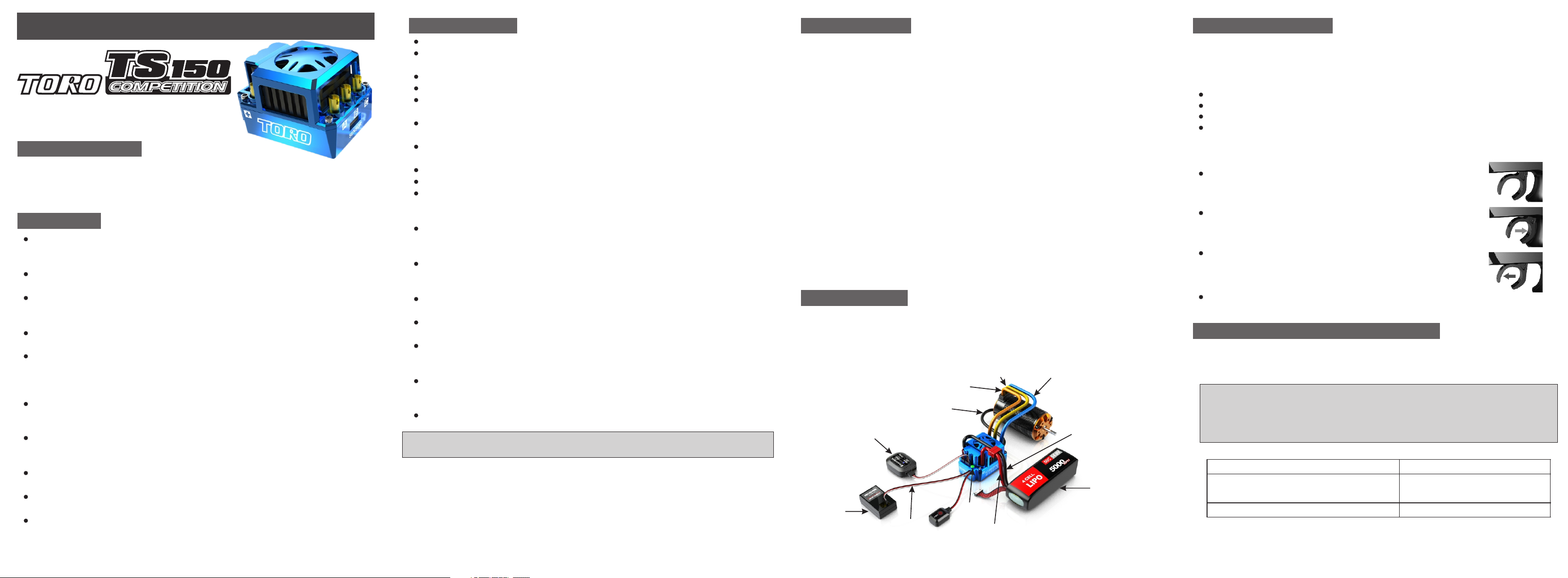
CONNECTION
Connect the motor sensor harness to ESC. Insert the 6 pin connector on the end of the
1)
motor's sensor wires into ESC's sensor harness socket.
Connect Throttle lead to ESC and other end to the Receiver (Throttle Channel, Ch2)
2)
Solder the motor and the ESC.
3)
4)
Connect ESC to battery pack.
Bluetooth Module
(Optional part)
Receiver
Throttle
lead
Orange motor
phase wires
(phaseC)
Motor
Sensor Wire
Yellow motor
phase wires
(phaseB)
Power
Switch
Red power wire
(battery positive)
Blue motor
phase wires
(phaseA)
Black power wire
(battery negative)
Battery
Pack
ESC CALIBRATION
Calibration is necessary for the first use of the ESC, or whenever used with a new/different
transmitter. Individual transmitter's signals for full throttle, full brake and neutral vary. You
must calibrate your ESC so that it will operate more effectively with your transmitter.
How to calibrate the ESC?
ESC switch OFF.
Connect the ESC to the battery and the motor.
Turn on the transmitter.
Press and hold the ESC switch for few seconds, the motor will ring long beep once. After
that, the red LED will blink the motor will ring like beep-beep-beep… in a row which indicates
it is time to set the neutral position, full throttle and full brake one by one. You could release
the ESC switch now.
Keep the throttle trigger in neutral position, press the ESC switch once, the
green LED will blink once then extinguish and the motor will ring beep once
which indicates the neutral position has been set.
Hold full throttle and press the ESC switch once, the green LED will blink
twice then extinguish and the motor will ring twice like beep-beep which
indicates the full throttle has been set.
Move the throttle trigger to full brake and hold full brake, press the ESC
switch once, the green LED will blink three times then extinguish and the
motor will ring three times like beep-beep-beep which indicates the full brake
has been set.
After the calibration is finished, keep the throttle in neutral position, the red
LED will stay ON, the ESC and the motor is ready to work.
ESC ON/OFF AND LED INDICATOR
ESC ON/OFF: When the ESC is OFF, press the switch once, the motor will ring beep once and
1.
the red LED will blink, then the ESC is ready to work. When the ESC is on, press the switch
once, the LED will extinguish and the ESC is OFF.
Note 1:
Note 2:
Explanation of LED Indicator
2.
The throttle trigger is in neutral position
The motor is running while the throttle trigger doesn’t
reach to the highest throttle/brake position
The throttle trigger is at the highest throttle/brake position.
After running at full load, the ESC will be very hot. In this case, please turn off the
ESC after it cools down.
When the motor is running, the ESC can't be powered off by pressing the switch;
when the motor stops working, the ESC can be powered off. In an emergency,
please disconnect the battery to power off the ESC.
Red LED is blinking
Green LED is blinking.
Green LED stays ON
4/ 83/ 82/ 81 /8
Page 2
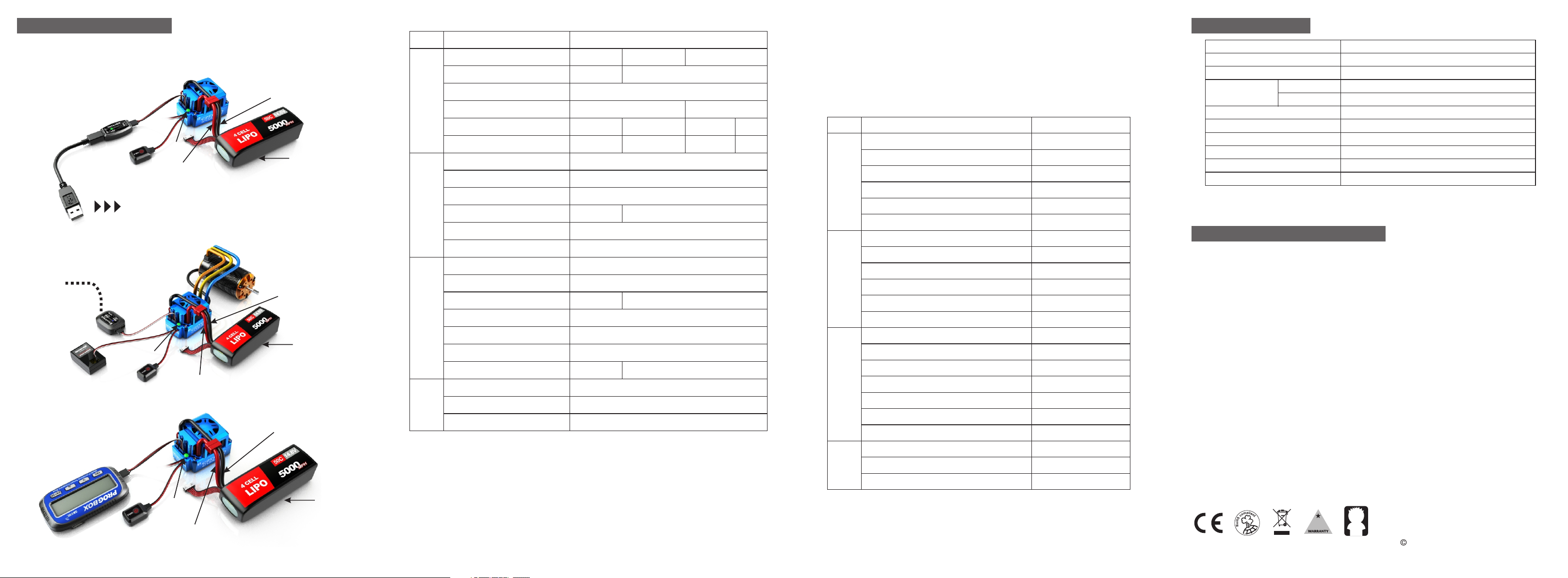
ESC PROGRAMMING
The ESC can be programmed by program box, PC (connected with SKYLINK) or smart phone
via bluetooth module.
1. PC via SKYLINK (optional part SK-600013)
Black power wire
(battery negative)
Power
Switch
Red power wire
(battery positive)
PC
2. Smart Phone via Bluetooth Module (optional part SK-600058)
SMART
Bluetooth
PHONE
Power
Switch
Red power wire
(battery positive)
3. Program Box (optional part SK-300046)
Black power wire
(battery negative)
Power
Switch
Red power wire
(battery positive)
Battery
Pack
Black power wire
(battery negative)
Battery
Pack
Battery
Pack
Programmable Items and Description
Section
General
Setting
Throttle
Control
Brake
Control
Turbo
Program Item
Running Mode
Motor Direction
Reverse Speed
Voltage Cutoff
ESC Overheat Protection
Motor Overheat Protection
Punch Rate Switch Point
1st Stage Punch Rate
2nd Stage Punch Rate
TH Input Curve
Throttle Dead Band
Throttle Status
Drag Brake
Brake Strength
Initial Brake
Brake Rate Switch Point
1st Stage Brake Rate
2nd Stage Brake Rate
Brake Input Curve
Turbo Timing
Turbo Full TH Delay
Turbo Engage Slope
Description
Forward/Brake
Normal
25-100% (in 1% increment)
6.0-25V (in 0.1V increment)
85℃/185℉
85℃/185℉
1-99%(in 1% increment)
1-30
1-30
Line
0.002-0.150ms
0-100%(in 1% increment)
0-100%
=Drag Brake
1-99%(in 1% increment)
1-20
1-20
Line
0-15 deg
0.05S-1S
1 deg/0.1S - 15 deg/0.1S
Forward/Brake/Reverse
Reverse
105℃/221℉
105℃/221℉
Custom
0-50%
Custom
Forward/Reverse
Auto (3.2V)
125℃/257℉
125℃/257℉
Disable
Disable
Profiles Preset
The users could preset and store 10 sets of profiles in the ESC. These data could be called
out for application at any time without any special program setting. The user could also reset
the profile according to his request. There is one factory default setting called Profile One
which is used for 1/8th off-road car.
Setting Details of Profile One
Profile One Setting Value (Default Value)
For 1/8 buggy, 1/8 sensor brushless motor X8S, KV2350 4Poles, 4S LiPo
Section
General
Setting
Throttle
Control
Brake
Control
Turbo
Program Item
Running Mode
Motor Direction
Reverse Speed
Voltage Cutoff
ESC Overheat Protection
Motor Overheat Protection
Punch Rate Switch Point
1st Stage Punch Rate
2nd Stage Punch Rate
TH Input Curve
Throttle Dead Band
Throttle Status
Drag Brake
Brake Strength
Initial Brake
Brake Rate Switch Point
1st Stage Brake Rate
2nd Stage Brake Rate
Brake Input Curve
Turbo Timing
Turbo Full TH Delay
Turbo Engage Slope
7/ 86/ 85 /8
Description
Forward/Brake
Normal
25%
Auto(3.2V/1S)
105℃/221℉
105℃/221℉
50%
3
3
Line
0.080ms
10%
75%
=Drag-Brabe
50%
10
16
Line
0 deg
0.10S
15deg/0.1S
SPECIFICATION
Constant/Burst Current
Motor Compatible
Car Compatible
Motor Limits
2-4S LiPo
2-6S LiPo
Resistance
Battery Cell Count
BEC Output
Size
Weight
FAN
150A/950A
Brushless Sensor or Sensorless ESC
1/8 Buggy, Truck and Monster
KV≤3000, 2-6 Poles
KV≤2400, 2-4 Poles
0.0002ohm
6-18S NiMH or 2-6S LiPo
6V@5A
58x41x38mm (LxWxH)
95g (w/o wire)
5V@0.3A
WARRANTY AND SERVICE
The TORO 8 Brushless ESC is guaranteed to be free from defects in materials or
workmanship for a period of 90 DAYS from the original date of purchase (verified by dated,
itemized sales receipt). Warranty does not cover incorrect installation, components worn by
use, damage to case or exposed circuit boards, cross-connection of battery/motor power
wires, overheating solder tabs, reverse voltage application, improper use or installation of
external BEC, damage resulting from thermal overload or short-circuiting motor, damage
from incorrect installation of FET servo or receiver battery pack, tampering with internal
electronics, allowing water, moisture, or any other foreign material to enter ESC or get onto
the PC board, incorrect installation/wiring of input plug plastic, allowing exposed wiring or
solder tabs to short-circuit, or any damage caused by a crash, flooding or natural disaster.
Because SKYRC has no control over the connection & use of the speed control or other
related electronics, no liability may be assumed nor will be accepted for any damage
resulting from the use of this product. Every SKYRC speed control & motor is thoroughly
tested & cycled before leaving our facility and is, therefore, considered operational. By the
act of connecting/operating speed control, user accepts all resulting liability. In no case shall
our liability exceed the product's original cost. We reserve the right to modify warranty
provisions without notice. This product is not intended for use by children under 14 years of
age without the strict supervision of an adult. Use of this product in an uncontrolled manner
may result in physical damage or injuries take extra care when operating any remote control.
Manufactured by
90
DAY S
14
+Yr
8/ 8
SKYRC TECHNOLOGY CO., LTD.
www.skyrc.com
2013 SkyRC Technology Co., Ltd. All Rights Reserved.
Ver 2.07504-0353-02
 Loading...