

Page 1
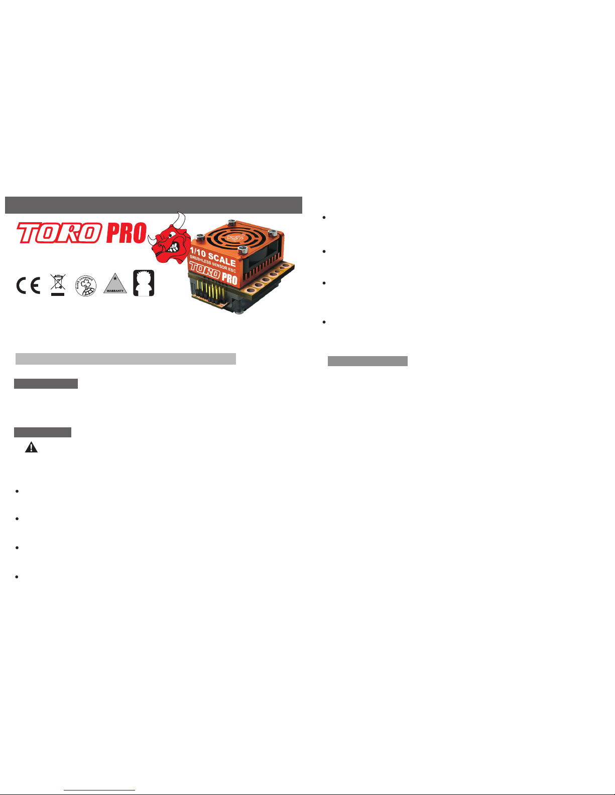
Congratulations and thank you for purchasing TORO PRO High performance sensor 1/10
Scale Brushless Motor Electronic Speed Control. The TORO PRO ,1/10 scale brushless ESC
represents a latest technologies, providing all the features and robust design qualities.
INTR OD UCT IO N
INSTRUCTION MANUAL
1)Plan Sp eed Cont rol Placement
Choo se a loc ati on fo r the sp eed control th at is pr otected fro m deb ris . To prevent radi o
inte rfe ren ce pl ace the spe ed contr ol as fa r away from the rad io re cei ver as poss ibl e
and keep the power wire s as short as possible.S ele ct a loc ati on th at has good airflow
vent ila tin g. If the ESC get s air fl ow, it will run c ool er; an d that means, it will be
more eff ici ent.
WARNING: This is an extremely powerful brushless motor system. We strongly
recommend removing your pinion gear for your own safety and the safety of those around you
before performing calibration and programming functions with this system. Please keep your
hands, hair, cloth, clear from the gear train and wheels of an armed high performance system.
SAF ET Y NOT E
1/ 8
WATER & ELECTRON ICS DON 'T MIX!
Never allow wat er, moist ure, or other foreign materials to get ins ide ESC , motor, or on the
PC Board s. Water damage will void the warranty!
INSULATE WIRES
Always insul ate exp osed wi ring wi th heat shrink tubing or electrical tap e to preve nt short
circuits, which can da mage ES C.
TRANSMITTER ON FIRS T
Turn on the transmitter first THEN turn on the spee d contr ol.
DISCONNECT BATTERIES WHEN NOT IN USE
Always disco nnect the batt ery pac k from the speed control whe n not in use to avoid short
circuits and po ssib le fire ha zard .
NO REVER SE VOLTAGE!
Reverse batt ery pol arit y can dama ge ESC & void warranty. Disconnect battery immedi atel y
if a revers e conne ctio n occur s.
14
+Yr
DAY S
Ver. 1.1
120
TIMING PRODU CES DAN GERO USLY HIGH SPEED
When Toro's ele ctro nic motor timing is enabled, the vehicl e speed ca n be increased
dramatically. Please take ext ra prec auti ons.
TIMING INCRE ASE ESC & MOTO R'S TEMPERATURE.
Electronic motor ti ming wi ll incr ease the temperatures of ESC and brushl ess mot or. Use
extreme caut ion whe n setti ng up and testing your application to avoi d overl oadi ng
and over heat ing.
2-3 LIPO OR 4- 8 NiMH CELLS ONLY
Never use fewer th an 2 or more than 3 LIPO cells (4 -8 NiMH) in the vehicle' s main bat tery
pack. The Toro 10 handles up to 12.6 Volts Max.
2)Mount Speed Control in Vehicle
Use double-sided tape to mount the speed control in vehicle(do not use CA glue).
Secure power capacitor module to chassis. You can use double-sides tape or a
tie wrap to mount power capacitor to the vehicle' s chassis or shock tower. Module
can also be tie-wrapped along the power wires.
Use double- sided tape to mount the switch where it will be easy to acc ess. Select
a position whe re it will not get damaged or get switched OFF durin g a crash or
roll-over.
Cut the ESC's BLUE, YELLOW & ORANGE silicone motor power wires to the desired
length and strip about 3.2mm-6.35mm (1/8”-1/4”) of insulation from the end of each
wire. “Pre-tin”the wire by heating the end and applying solder until it is thoroughly
covered.
CAUTION: By very careful not to splash yourself with hot solder.
Place the ESC's BLUE Phase ‘A’ motor wire onto motor's ‘A’ solder tab and solder.
Use soldering iron to apply heat to exposed wire; begin adding solder to tip of soldering
iron and wire. Add just enough solder to form a clean and continuous joint from the
plated area of the solder tab up onto the wire. Solder the ECS's YELLOW Phase
‘B’ motor wire to the motor's ‘B' solder tab and Solder the ESC's ORANGE
Phase ‘C' motor wire to motor’s ‘C’ solder tab.
3) Soldering
BEFORE YO U BEG IN
2/ 8
PLEASE READ ALL INSTRUCTION S BE FO RE O PE RATION
Suppo rt Both Sensor or Sensor-less Br ushless Motor
1/10 SCALE ADVENCE
RACING SPEED CONTROLLER
Ver. 1.1
P120
Page 2
IMPO RTAN T NO TE : Ca li brati on i s ne ce ss ary for t he f ir st u se o f the ESC , or w he ne ve r
used w it h a ne w/ di ff er en t trans mi tt er.
Indi vi du al t ra ns mitte r' s si gn al s for ful l th ro tt le , full br ak e an d ne ut ra l vary. You must
cali br at e yo ur E SC s o that it w il l op er at e more effect iv el y wi th y ou r trans mi tt er.
1)Pr og ra mm in g Card(Op ti on al P ar t)
3/ 8 4/ 8
From this point on, when you connect batteries and turn on the switch, the ESC will give the
initialization tone and flash, and the arming tone will ring second or two later. If the ESC is
programmed for the Auto-Lipo setting, it will beep the number of cells in you Lipo pack
between the initialization tones and the arming tones. After the arming tone plays, the ESC
will ACTIVE and will respond to the throttle application.
ESC/ TR ANS MI TER C AL IBR ATI ON
For us er s wi th a F ut ab a Transm it te r, yo u mu st reve rs e th e th ro ttle ch an ne l si gn al o n
your t ra ns mi tt er. P lease r ef er t o yo ur F utaba i ns tr uc ti ons.
Red LE D bl in ks w hi les bee pi ng , in di ca ting it 's t im e to p us h full
brak e. M ov e th ro tt le trig ge r to f ul l br ake and w ai t fe w se co nds,
the ES C wi ll b li nk r ed L ED and ri ng s 1s ec on d indic at in g fu ll b rake
meas ur e.
Yell ow L ED b li nks whi le s be ep in g, indi ca ti ng i t' s time fo r ne ut ra l.
Rela x tr ig ge r to n eu tral (c en te r) . Th e ES C wi ll now ri ng 1 s ec on d
and fl as h th e ye ll ow L ED rapi dl y to a cc ep t the neu tr al p os it ion.
ESC wi ll b li nk L ED a nd ring o ne s ec on d in di catin g th at i t is a rm ed.
ESC PR OG RAM MI NG
Ver. 1.1 Ver. 1.1
How to C al ib ra te E SC
ESC sw it ch O FF.
Tur n on t he Tr an smitt er.
Hold f ul l th ro tt le o n your tr an sm it te r and tur n th e ES C' s sw itch ON .
Keep h ol di ng f ul l th rottl e on t he t ra ns mitte r. The ES C wi ll f la sh es
LED an d ri ng t he i ni ti ali za ti on t on es .
Wai t 2 se co nd s
Gree n LE D bl in ks r ap idl y an d th e mo to r wi ll ring s 1 se co nd i nd icati ng
full t hr ot tl e me as ured.
3)Man ua l Pr og ra mm ing
Manu al P ro gr am mi ng TOR O PR O is a s simpl e as a ns we ri ng a f ew ques ti on s. T he
TOR O PR O as ks q uesti ng b y be ep in g a setti ng n um be r, fo ll owed by t he p os si bl e
sett in g va lu es . Th er e ar e eight s et ti ng s th at can be p ro gr am me d in t he TOR O .
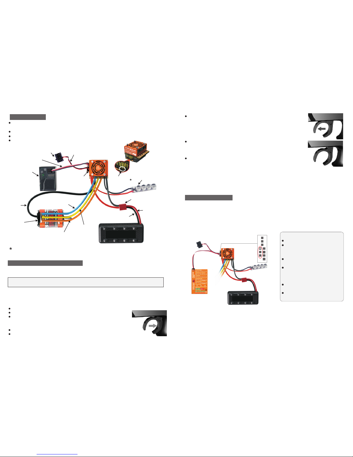
CONN EC TIO NS
Conn ec t mo to r se ns or harn es s to E SC . In sert th e 6 pi n co nn ec tor on th e en d of
the mo to r' s se ns or w ires in to E SC 's s en sor har ne ss s oc ke t.
Conn ec t ON /O FF s wi tch to po we r ou tp ut p ins.
Conn ec t Thro tt le l ea d to E SC and ot he r en d to t he R eceiv er ( Th ro tt le C hanne l, C h2 )
Conn ec t ES C to b at te ry pack
Programming Card allows you to modify the most commonly used settings in your TORO
PRO controller all at the touch of a single button. No computer needed. Simply connect the
Programming Card to the SKYLink interface pins of the controller and power the programming
card as described below. Click the button to scroll through and change the indicated
settings. All the settings will show on the programming card at once. Can't get any easier!
Li-Po battery
SKYLink
interface Pins
+
S
SKYLink interface pins allows you to connect the Program Card and SKYLink Interface
Adaptor to you ESC directly for easy programming.
ESC O N/OFF
swi tch
Bat tery co nnect or
Red p ower wi re
(ba ttery p ositi ve)
Bla ck powe r wire
(ba ttery n egati ve)
Ora nge mot or
pha se wire s
(ph aseC)
Blu e motor
pha se wire s
(ph aseA)
Yello w motor
pha se wire s
(ph aseB)
TOR O
Sen sor-b ased
Bru shles s motor
(54 0-cla ss)
Sen sor
har ness
Rec eiver
Thr ottle l ead
Fan
out put
pin s
Swi tch
out put
pin s
SKY Link
int erfac e pins
Pow er capa citor
Li-Po battery
2)SKYLink Programming Interface(Optional Part)
Optional fully adjustable PC interface,which includes a USB cord and USB Interface
Instruction for Program Ca rd
Turn off the ESC.
Connect the lead from program card
to the SKYLink interface pins of
the controller.
Turn on the ESC to apply power to
both ESC and Program Card.
All the cur ren t se tt ing s wi ll be
displayed on the correspond LEDs.
Press and release button to move
between settings.
Press and hold button to change the
value for that setting.
Turn off the ESC and disconnect lead
from Program Card.
Instruction for Program Ca rd
Page 3

You must answer yes or no to the setting values as they are presented by TORO PRO.
When you enter programming mode the ESC will emit a sequence of beeps and LED flashes
that tell you which programming step you are in. There are two parts to the beep sequence.
The first set of beeps indicates the 'Setting Number (Question), e.g. Brake/Reverse Type, and
the second set of beeps indicates a Setting Value, e.g. Reverse Lockout. Answering "No" to a
Setting value will cause the ESC to ask for the next value in that section. After a "Yes" answer
is accepted, the ESC knows you aren't interested in any other option in that section, so it
skips to the first option in the next section.
" " " "
Note: If you answer "no" to all Setting Values for a particular Setting Number, the ESC will
keep whatever value had been previously programmed. Only by answering "Yes" to a Setting
Value will the ESC store/change that value.
5/ 8 6/ 8
Plug Battery into the TORO PRO
Hold full throttle on your transmitter
Turn the ESC switch ON
TORO PRO flashes LED and rings once
Wait few seconds.
TORO PRO flashes LED and rings 1 second indicating that it is ready for CALIBRATION mode
Continue to hold full throttle
TORO PRO flashes LED while beeping
Wait another few seconds
TORO PRO flashes LED and rings 1 second
TORO PRO flashes LED while beeping indication that you are in PROGRAMMING mode
Let trigger go neutral (Centre)
At thi s po in t th e TORO P RO w il l be f la shing /b ee pi ng t he f ollow in g se qu en ce:
Beep -P au se -B ee p... an d th en r ep ea ts
This i nd ic at es t ha t you are a t Qu es ti on 1 a nd it is as ki ng t o ac ce pt/re je ct v al ue 1 .
Pro grammab le Feat ures
Question (Setting)
How to E nt er P ro gr am ming Mo de
Ver. 1.1 Ver. 1.1
1)Rever se Lockout (D)*
2)50%(D )*
2)50%(D )*
5)Disab le
1)Disab le(D)*
2)Norma l(D)*
2)Auto- Lipo(D )*
2)Norma l(D)*
Note: Fact ory Default s are indicat ed by asterisk (D) *
1)Large
4)Very Small
5)Small est
1)D isabl e
When answering a question, you will need to move the trigger to yes (full throttle) position or
the no (full brake) position and keep it there for about 3 seconds. When the ESC has
accepted your answer it will confirm your reply by flashing the LED and emitting a beeping
tone. Release the trigger allowing it to go to Neutral to confirm that you are ready for ESC to
ask you next question. You are not required to continue through all eight programming
options. For example, if you wish only to change the Brake/Reverse Type (Option 1) then after
programming that setting you can disconnect power from the ESC and you're ready to run.
Disconnecting the controller in the middle of programming simply retains the values for the
remaining programming options that were previously set up.
1)25%
2)Mediu m
3)Small
4)Lowes t(D)*
Page 4

SP EE D C ON T RO L S PE C IF IC AT I ON
7/ 8 8/ 8
2011 SkyRC Technology Co., Ltd. All Rights Reserved.
Manufactured by
SKYRC TECHNOLOGY CO., LTD.
www.skyrc.com
Sol ut io n: Tr y mo vi ng the throttle t ri m on e wa y, the n th e ot he r (u su al ly towards th e
thr ot tl e si de i s best). If you r tr an sm it te r ha s a 50/50 and 7 0/ 30 s et ti ng f or the
thr ot tl e, s et i t for 50/50 and r et ry c al ib ra ti on . Also, if you h av e ch an ge d th e
dea d ba nd t o a narrower band you m ay w an t to t ry going ba ck t o th e "n or ma l"
set ti ng .
Prob le m: M y TO RO E SC m ay o r ma y not arm , bu t it w il l no t ca libra te t o my t ra ns mitte r
TROU BL E SHO OT ING
The TORO PRO Brushless ESC is guaranteed to be free from defects in materials or
orkmanship for a period of 120 DAYS from the original date of purchase (verified by dated,
itemized sales receipt). Warranty does not cover incorrect installation, components worn by
use, damage to case or exposed circuit boards, damage due to timing, damage from using
more than 3 Li-Po cells input voltage, cross-connection of battery/motor power wires,
overheating solder tabs, reverse voltage application, improper use or installation of external
BEC, damage resulting from thermal overload or short-circuiting motor, damage from incorrect
installation of FET servo or receiver battery pack, tampering with internal electronics, allowing
water, moisture, or any other foreign material to enter ESC or get onto the PC board, incorrect
installation/wiring of input plug plastic, allowing exposed wiring or solder tabs to short-circuit, or
any damage caused by a crash, flooding or natural disaster. Because SKYRC has no control
over the connection & use of the speed control or other related electronics, no liability may be
assumed nor will be accepted for any damage resulting from the use of this product.Every
SKYRC speed control & motor is thoroughly tested & cycled before leaving our facility and is,
therefore, considered operational. By the act of connecting/operating speed control, user
accepts all resulting liability. In no case shall our liability exceed the product's original cost. We
reserve the right to modify warranty provisions without notice. This product is not intended for
use by children under 14 years of age without the strict supervision of an adult. Use of this
product in an uncontrolled manner may result in physical damage or injurise take extra care
when operating any remote control vehicle.
PROD UC T WARR AN TY
Solu ti on : Mo st c al ibrat io n is su es c an be sol ve d by c ha ng ing set ti ng s on t he t ra nsmit te r.
Make sur e yo u ha ve b ot h your th ro tt le a nd b rake en dp oi nt s (c al led EPA or
ATV on yo ur r adio) o n th e th ro tt le chan ne l ou t to b et we en 100 to 1 20 %. M ak e
sure if yo u ha ve a F ut ab a or Futa ba m ad e tr an smitt er t o ha ve t he t hr ottle
channe l se t to t he r ev ersed p os it io n.
Sol ut io n: M ak e su re y ou 're using hig h qu al it y ba tt er ie s and a batte ry c on ne ct or c ap ab le
of hi gh a mp f lo w (40-100 amps) . Th is behavior is ve ry t yp ic al o f a battery pack
Sol ut io n: M ak e su re t he ESC's rece iv er p lu g is p lu gg ed into channel 2 o n th e re ce iv er,
and t ha t it 's p lu gged in with th e co rr ec t or ie nt at ion. Double che ck y ou r so ld er
con ne ct io ns o n th e battery plug, a nd m ak e su re t he battery is s ho wi ng g oo d
vol ta ge .
SPECIFICATIONS ARE SUBJECT TO CHANGE WITHOUT NOTICE.
Ver. 1.1
Ver. 1.1
To conform to ROAR's Sportsman Class racing rules and help race organizers monitor driver
compliance in non-timing race classes, Toro 10 ESC has included a feature in this speed
control that indicates when the ESC has its electronic motor timing advancement feature
activated.
At all times when the speed control is powered ON and the Dynamic Motor Timing is turned
ON and set to a level greater than zero timing advance, the ESC's white status LED will be
illuminated during normal operation.
TIMI NG I ND ICATO R LE D
Pro bl em : My b at te ry p ac k is plugge d in to t he E SC a nd nothing is wor ki ng
Prob le m: M y ES C ca li brate s fo r th e fu ll t hrott le a nd f ul l br ake pos it io ns b ut w on 't
calibr at e to t he n eu tral th ro tt le p os ition . (O ra ng e LE D ke eps fla sh in g)
tha t is h av in g di ffi cu lt y pr ov id in g th e power your ve hi cl e/ sy st em r eq ui re s for
top p er fo rm an ce . Us e copper bars t o co nn ec t ce ll s rather than wel de d ta bs .
Cop pe r ba rs h av e a much lower re si st an ce .
Sol ut io n: S et mot or rotation to co unt er- clockwis e–Elec tro nic motor timi ng adv ancement
onl y fu nc ti on s in counter-clockwis e ro ta ti on d ir ec ti on . You may s ol ve t hi s
pro bl em b y di sa bl e motor timing.
Sol ut io n: R ed uc e ti mi ng level settin g in E SC . El ec tr on ic motor ti mi ng s et t oo h ig h.
Inc re as e ge ar r at io /Reduce pinion.
Pro bl em : Ti mi ng Does Not Ope ra te P ro pe rl y
Pro bl em : My v eh ic le a ct s like it has " tu rb o la g" ( po or acceleration /p un ch f or t he f ir st
few f ee t or y ar ds )
Pro bl em : Sp ee d Co nt ro l Ru ns Excessivel y Ho t
Sol ut io n: T he ESC has bu il t in t he rm al p ro tection circu it ry t o pr ot ec t th e ESC from
bei ng d am ag ed d ur in g running. If t he t he rm al p ro te ct ion shuts the E SC o ff, the
red LE D wi ll f la sh in g. Check the KV v al ue o f mo to r and make su re t he p in io n is
not t oo l ar ge f or the motor. On ce t he E SC c ool down, it wi ll r es um e wo rk in g.
Pro bl em : Th e ES C sh ut off and re d LE D fl as hi ng
7504-0202-01
Controls,TORO PRO
1/10 Scale
Input Power(Cells)
BEC Output
Dimensions(Without fan)
Weight (Without wires)
Status LED(2 LEDs)
Thermal Overload Protection
Motor
Limits
Compatibility
Motor Type
2S LiPo
(4-6S NiMH)
3S LiPo
(7-8S NiMH)
Fwd/Brk or Fwd/Rev
White LED, 3 Color LED ( Red, Green & Orange )
Yes
36.5X42X30mm (1.44X1.65X1.19in)
50g (1.76oz)
6.0Volts, 3Amp,Built-in BEC
2-3S LiPo/LiFe, 4-8 NiMH (12.6V Max)
Sensored Brushless Motor or Sensorless Brushless Motor
Sensored and sensorless Brushless Motors
On Road≥4.5T Off Road ≥6.5T
On Road≥6.5T Off Road ≥9.5T
 Loading...