

Page 1
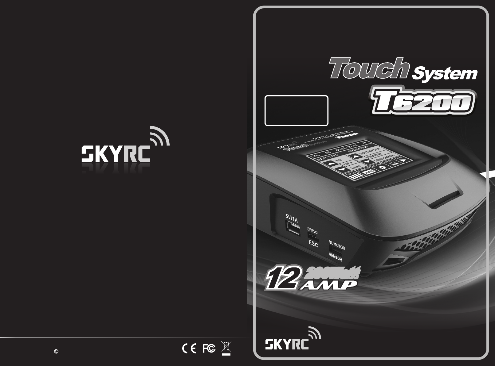
INSTRUCTION MANUALINSTRUCTION MANUAL
TOUCH SENSITIVETOUCH SENSITIVE
3.2”3.2”
COLOR LCD SCREENCOLOR LCD SCREEN
(320x240 dot)(320x240 dot)
200Watt200Watt200Watt
Manufactured by
SKYRC TECHNOLOGY CO., LTD.
www.skyrc.com
All specifications and figures are subject to change without notice.
Printed in China 2013
7504-0347-01
Professional Balance Charger / Discharger
Battery Meter / Motor RPM Tester / Servo Tester
Version 1.01
Page 2

TABLE OF CONTENTS INTRODUCTION
INTRODUCTION
MAIN FEATURES
WARNING AND SAFETY NOTES
HOMEPAGE
OPERATION PROGRAM
CHARGING STATUS MONITOR
USING THE CHARGE CONTROL SOFTWARE “CHARGE MASTER”
BATTERY METER
MOTOR RPM TESTER
SERVO TESTER
MEMORY PRESET-DATA STORE/LOAD
SETTING
ERROR MESSAGE
SPECIFICATION
RECOMMENDED ACCESSORIES
CONFORMITY DECLARATION AND LIABILITY EXCLUSION
WARRANTY AND SERVICE
01
03
05
07
08
14
14
15
16
17
18
19
21
22
23
24
24
INTRODUCTION
Congratulations on your choice of the SKYRC T6200 Professional Balance Charger/
Discharger Battery Meter / Motor RPM Tester / Servo Tester from SKYRC Technology
Co., Ltd. This unit is simple to use, but the operation of a sophisticated automatic charger
such as SKYRC T6200 does require some knowledge on the part of the user. These
operating instructions are designed to ensure that you quickly become familiar with its
functions. It is therefore important that you read right through the Operating Instructions,
Warning and Safety Notes before you attempt to use your new charger for the first time.
We hope you have many years of pleasure and success with your new battery charger.
SKYRC T6200 represents the newest technology of chargers with its advanced touch
system. As it is a “touch” charger, of course the screen plays an important role in this
system. We equip it with a 3.2” (320*240 dot) touch sensitive color LCD screen. It is
intuitive as all the operating instruction and changing status can be displayed in this
screen and the touch screen can register the users' input precisely so that the users can
have a wonderful and comfortable “touch” experience.
When the charger is working, the users could check the information of charging capacity,
cell voltage, charging time, external and internal temperature easily. What's more, it can
also display the voltage in a graphic which helps the user monitor the charging status all
the time.
SKYRC T6200 is a high-performance, micro processor control charge/discharge station
with battery management suitable for use with all current battery types. With integral
equalizer for six-cell Lithium- Polymer (LiPo), Lithium-Ferrum (LiFe) and Lithium-Ion
(LiIon) batteries; maximum 12A charge current; maximum 200W charge power. It can be
powered by a 12V car battery or a high quality AC-DC power supply in the range of 12V
to 18V DC output, with minimum current rating of 20A to insure reliable performance.
When a NiMH/NiCd battery is fully charged, the unit terminates the process using the
Delta-Peak method. Lithium and lead (Pb) batteries are charged using the CC-CV
method.
The fan cooling system is so smart and efficient. The fan speed is controlled by internal
temperature sensor.
It also adds lithium Battery Volt Meter, Motor RPM Tester and Servo Tester functions. It is
convenient for user to get some useful information with this charger.
Please BE SURE to read these INSTRUCTIONS, WARNING and SAFETY NOTES
before you use the charger for the first time.
It can be dangerous to mis-handle batteries and battery chargers, as there is always a
risk of batteries catching fire and exploding.
Please read this entire operating manual completely and attentively before using this
product, as it covers a wide range of information on operating and safety. Or please do
use this product in company with a specialist!
T6200
01
Page 3
INTRODUCTION
MAIN FEATURES
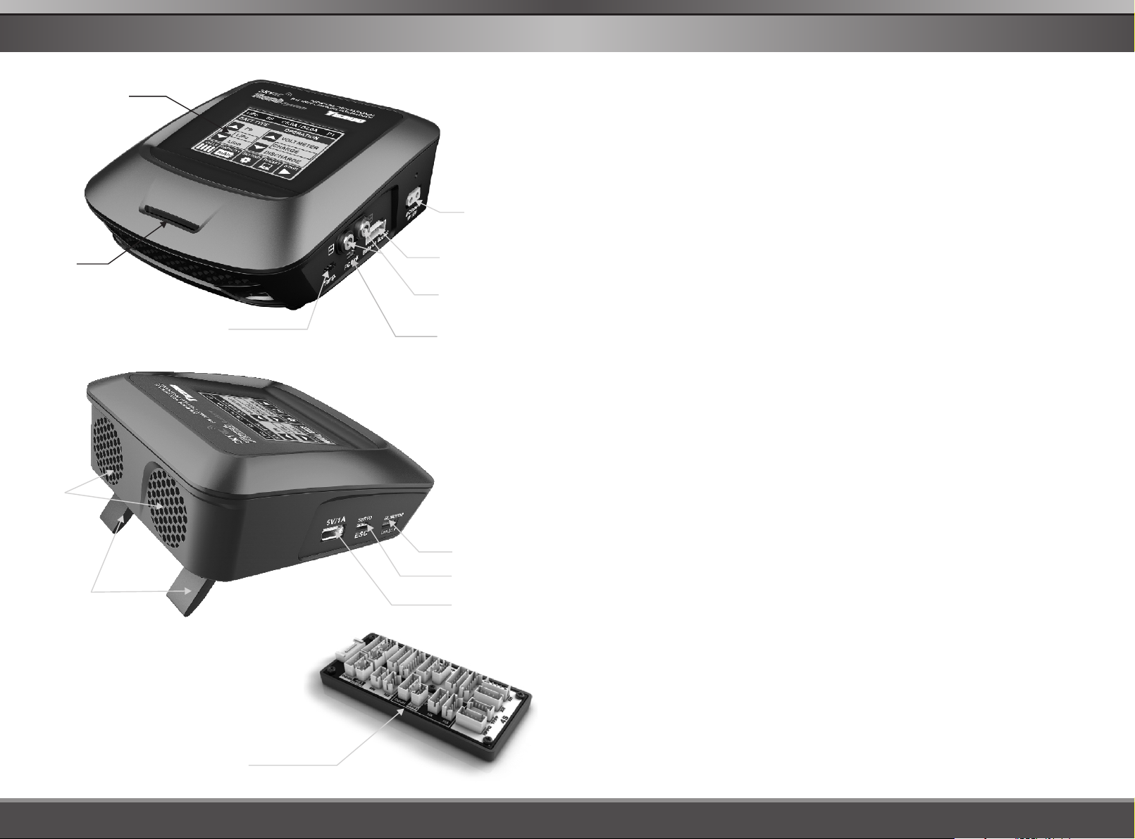
Color LCD
Touch Screen
3.2"(320x240 dot)
Air Intake
Duct
Cooling
Fan
Temperature
Probe Socket
DC Input
11-18V AC
Balance Socket-XH
Battery Socket
USB Port for PC
Control & Firmware
Upgrade
FEATURES
Touch System
Equipped with a 3.2” touch sensitive color LCD screen, it is intuitive as all the operating and
changing status can be displayed in this screen. What's more, the touch screen can register the
users' input precisely so that the users can have a wonderful and comfortable “touch” experience.
Optimized Operating Software
SKYRC T6200 Charger features the so-called AUTO function that set the feeding current during the
process of charging or discharging. Especially for lithium batteries, it can prevent the overcharging
which may lead to an explosion due to the user's fault. It can disconnect the circuit automatically and
alarm once detecting any malfunction. All the programs of this product were controlled through two
way linkage and communication, to achieve the maximum safety and minimize the trouble. All the
settings can be configured by users!
Charging Status Monitor
When the charger is working, the users could check the information of charging capacity, cell
voltage, charging time, external and internal temperature easily. What's more, it can also display the
voltage in a graphic which helps the user monitor the charging status all the time.
Internal Independent Lithium Battery Balancer
SKYRC T6200 Charger employs an individual-cell-voltage balancer. It isn't necessary to connect an
external balancer for balance charging.
Balancing Individual Cells Battery Discharging
During the process of discharging, SKYRC T6200 Charger can monitor and balance each cell of the
battery individually. Error message will be indicated and the process will be ended automatically if
the voltage of any single one cell is abnormal.
Adaptable to Various Type of Lithium Battery
SKYRC T6200 Charger is adaptable to various types of lithium batteries, such as LiPo, LiIon and the
new LiFe series of batteries.
Tilt Stand
02
Multiple Balancing Board
Brushless Motor
Sensor Port
Servo/ESC Port
USB 5V/1A
Fast and Storage Mode of Lithium Battery
Purposes to charge lithium battery varies, 'fast' charge reduce the duration of charging, whereas
'store' state can control the final voltage of your battery, so as to store for a long time and protect
useful time of the battery.
Cyclic Charging/Discharging
1 to 5 cyclic and continuous process of charge>discharge or discharge > charge is operable for
battery refreshing and balancing to stimulate the battery's activity.
Memory Preset
The charger can store up to 5 different charge/discharge profiles for your convenience. You can keep
the data pertaining to program setting of the battery of continuous charging or discharging. Users
can call out these data at any time without any special program setting.
Terminal Voltage Control (TVC)
The charger allows user to set the charge/discharge end voltage.
Battery Volt Meter
The user can check Lithium battery's total voltage, the highest voltage, the lowest voltage and each
cell's voltage; and can check Nickel and Pb battery's total voltage.
T6200T6200
03
Page 4
MAIN FEATURES
WARNING AND SAFETY NOTES
Motor RPM Tester
Users connect the sensor motor and charger with sensor wire, set the pulse width and test the RPM
of the motor.
Servo Tester
Connect the servo and the charger with wire, change the pulse width value and check whether the
servo works or not.
Re-Peak Mode of NiMH/NiCd Battery
In re-peak charge mode, the charger can peak charge the battery once, twice or three times in a row
automatically. This is good for making certain the battery is fully charged, and for checking how well
the battery receives fast charges.
Delta-peak Sensitivity for NiMH/NiCd
Delta-peak sensitivity for NiMH/NiCd battery: The automatic charge termination program based on
the principle of the delta-peak voltage detection. When the battery's voltage exceeds the threshold,
the process will be terminated automatically.
Automatic Charging Current Limit
You can set up the upper limit of the charging current when charging your NiMH or NiCd battery, it is
useful for the NiMH battery of low impedance and capacity in the 'AUTO' charging mode.
Capacity Limit
The charging capacity is always calculated as the charging current multiplied by time. If the charging
capacity exceeds the limit, the process will be terminated automatically when you set the maximum
value.
Temperature Threshold*
The battery's internal chemical reaction will cause the temperature of the battery to rise. If the
temperature limit is reached, the process will be terminated.
Processing Time Limit
You can also limit the maximum process time to avoid any possible defect
PC Control Software “Charge Master”
There is a mini USB port in the charger which can be used to connect it to the PC. You need optional
USB cable (USB A Male to Mini B Male) which is not included in the package. The free “Charge
Master” software gives you unparalleled ability to operate the charger through your computer. You
can monitor pack voltage, cell voltage and other data during the charging, view charge date in realtime graphs. And you can initiate, control charging and update firmware from “Charge Master”.
When your charger is connected to computer, the “Charger Master” takes over the control of charger.
You can control and operate the charger via the “Charger Master” only.
Multi-Language and Four Color Theme Optional
There are two languages and four kinds of color theme stored in the charger and users could select
the display language and color theme as basing on personal preference.
Inner resistance of battery pack
Measure Inner resistance of battery pack inclusively all connectors and leads.
This function is available by connecting optional temper ture probe which is not included in the package.a
Users can control and monitor the charge through computer when Charge Master software is installed.
You can download Charge Master software from our website
www.skyrc.com
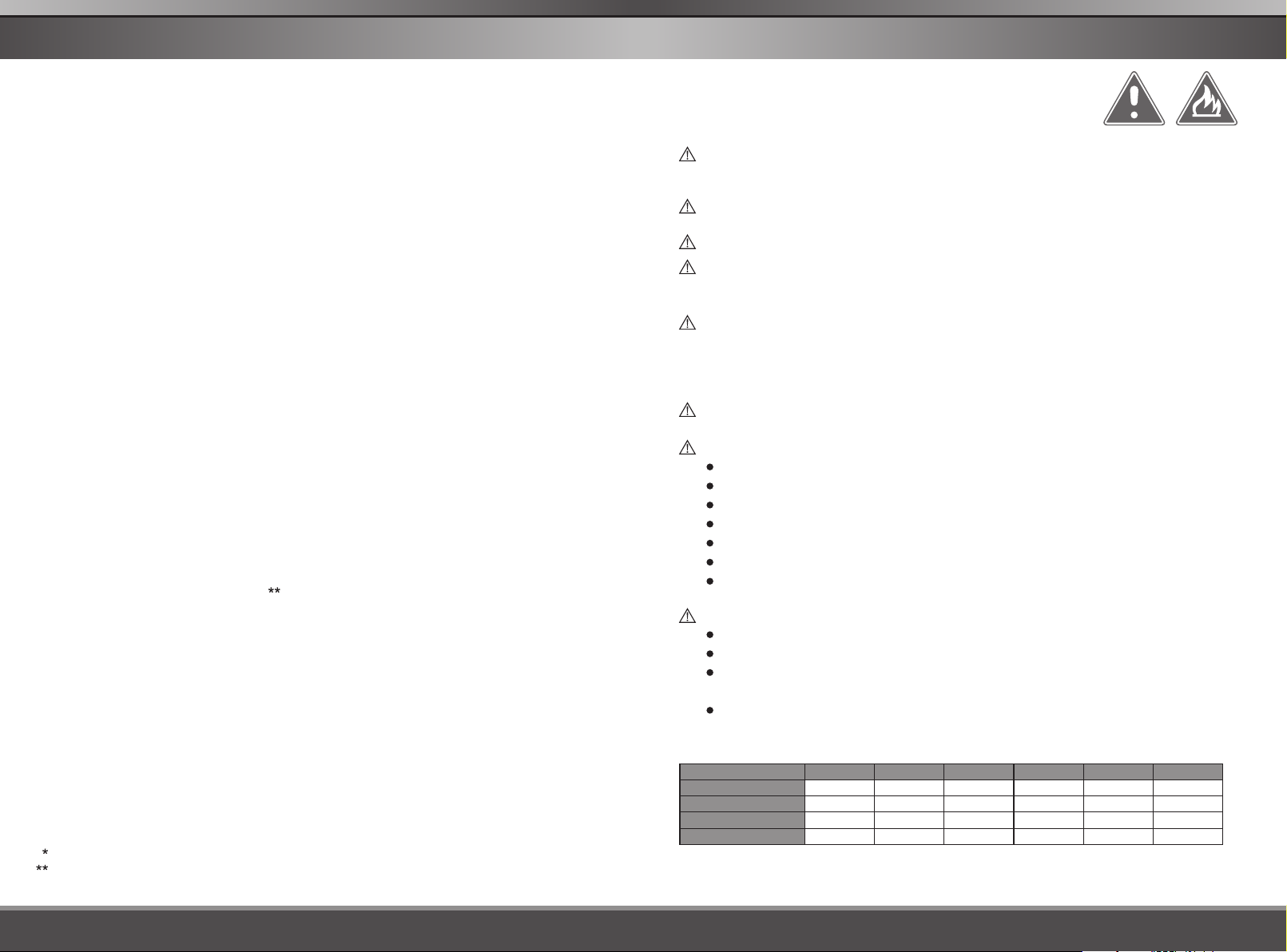
WARNING AND SAFETY NOTES
These warnings and safety notes are particularly important. Please
follow the instructions for maximum safety; otherwise the charger
and the battery can be damaged or at worst it can cause a fire.
Never leave the charger unattended when it is connected to its power supply. If any
malfunction is found, TERMINATE THE PROCESS AT ONCE and refer to the operation
manual.
Keep the charger well away from dust, damp, rain, heat, direct sunshine and vibration.
Never drop it.
The allowable DC input voltage is 11-18V DC.
This charger and the battery should be put on a heat-resistant, non-flammable and nonconductive surface. Never place them on a car seat, carpet or similar surface. Keep all
flammable volatile materials away from the operating area.
Make sure you know the specifications of the battery to be charged or discharged to
ensure it meets the requirements of this charger. If the program is set up incorrectly, the
battery and charger may be damaged. Fire or explosion can occur due to overcharging.
This warranty is not valid for any damage or subsequent damage arising as a result of a
misuse or failure to observe the procedures outlined in this manual.
To avoid short circuiting between the charge lead, always connect the charge cable to the
charger first, then connect the battery. Reverse the sequence when disconnecting.
Never attempt to charge or discharge the following types of batteries:
A battery pack which consists of different types of cells (including different manufacturers)
A battery that is already fully charged or just slightly discharged
Non-rechargeable batteries (pose an explosion hazard)
A faulty or damaged battery
A battery fitted with an integral charge circuit or a protection circuit
Batteries installed in a device or which are electrically linked to other components
Batteries that are not expressly stated by the manufacturer to be suitable for the
currents the charger delivers during the charge process
Please bear in mind the following points before commencing charging:
Did you select the appropriate program suitable for the type of battery you are charging?
Did you set up adequate current for charging or discharging?
Have you checked the battery voltage? Lithium battery packs can be wired in parallel and
in series, i.e. a 2-cell pack can be 3.7V (in parallel) or 7.4V (in series).
Have you checked that all connections are firm and secure? Make sure there are no
intermittent contacts at any point in the circuit.
Standard Battery Parameters
Nominal Voltage
Max Charge Voltage
Storage Voltage
Min. Discharge Voltage
Be very careful to choose the correct voltage for different types of battery otherwise you may cause
damage to the batteries. Incorrect settings could cause the cells to fire or explode.
LiPo LiIon LiFe
3.7V/cell 3.6V/cell 3.3V/cell
4.2V/cell 4.1V/cell
3.7V/cell3.8V/cell 3.3V/cell
3.0-3.3V/cell 2.9-3.2V/cell 2.6-2.9V/cell 0.1-1.1V/cell 0.1-1.1V/cell
3.6V/cell
NiCd MiMH
1.2V/cell 1.2V/cell 2.0V/cell
1.5V/cell 1.5V/cell 2.46V/cell
n/a n/a n/a
Fire Hazard!WARNING
Pb
1.8V/cell
T6200T6200
0504
Page 5
WARNING AND SAFETY NOTES HOMEPAGE
Charging
During charge process, a specific quantity of electrical energy is fed into the battery. The
charge quantity is calculated by multiplying charge current by charge time. The maximum
permissible charge current varies depending on the battery type or its performance, and
can be found in the information by the battery manufacturer. Only batteries that are
expressly stated to be capable of quick-charge are allowed to be charged at rates higher
than the standard charge current.
Connect the battery to the terminal of the charger: red is positive and black is negative.
Due to the difference between resistance of cable and connector, the charger can not
detect resistance of the battery pack, the essential requirement for the charger to work
properly is that the charge lead should be of adequate conductor cross-section, and high
quality connectors which are normally gold-plated should be fitted to both ends.
Always refer to the manual by the battery manufacturer pertaining to charging methods.
Operate according to their recommended charging current and charging time. lithium
batteries, in particular, should be charged strictly according to the manufacturer’s
instruction.
Close attention should be paid to the connection of lithium batteries.
Do not attempt to disassemble the battery pack arbitrarily.
Please get highlighted that lithium battery packs can be wired in parallel and in series. In
the parallel connection, the battery's capacity is calculated by multiplying single the
battery's capacity by the number of cells, bearing in mind that total voltage stays the
same. If the voltage is imbalanced, it may cause a fire or explosion. Lithium batteries are
recommended to charge in series.
Discharging
The main purpose of discharging is to clean the residual capacity of the battery, or to
reduce the battery' voltage to a defined level. The same attention should be paid to the
discharging process as the charging process. The final discharge voltage should be set up
correctly to avoid deep discharging. Lithium batteries cannot be discharged to lower than
the minimum voltage, or it will cause a rapid loss of capacity or a total failure. Generally,
lithium batteries don't need to be discharged. Please pay attention to the minimum voltage
of lithium batteries to protect them.
Some rechargeable batteries have a memory effect. If they are partly used and recharged
before the whole charge is accomplished, they remember this and will only use that part of
their capacity next time. This is a 'memory effect' It is said that NiMH and NiCd batteries
are suffering from memory effect. NiCd has more ‘memory effect’ than NiMH.
Lithium batteries are recommended to be discharged partially rather than fully. Frequent
full discharging should be avoided if possible. Instead, charge the battery more often or
use a battery of larger capacity. Full capacity cannot be reached until it has been
subjected to 10 or more charge cycles. The cyclic process of charge and discharge will
optimize the capacity of battery pack.
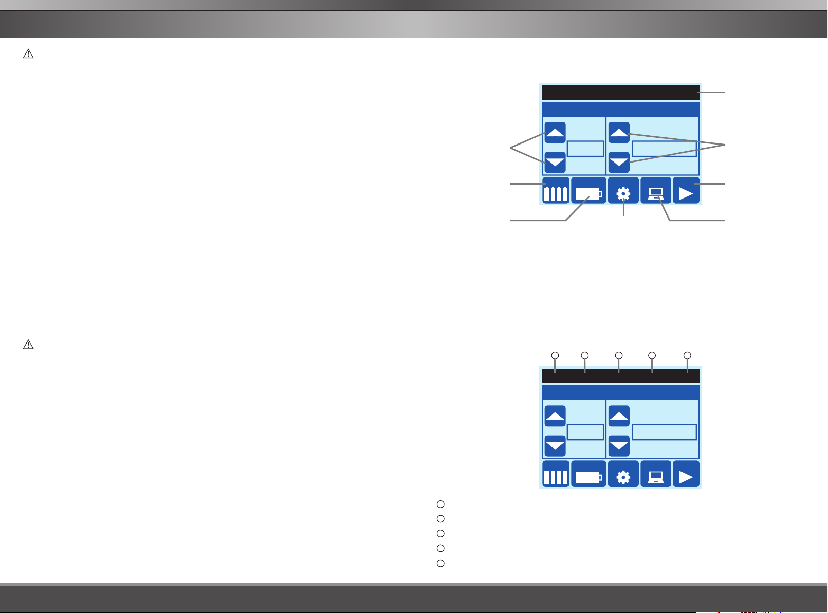
HOMEPAGE
When you power on the charger, you will see following screen. That is the homepage of the system.
①
③
⑧
②
④
LiPo
BATT TYPE
CELLS CAPACITY
6S
Pb
LiPo
Lilon
C6.0A / D2.0A
OPERATION
VOLT METER
CHARGE
DISCHARGE
PRESET
P1
STARTSETTING
mAh
⑤
①
It indicates the current settings(battery type / battery cells / charge current/discharge current).
②
Batt Type - Battery Type selection button
③
Operation - Operation Program selection button
④
Cells - Battery Pack Cells number selection button
⑤
Battery Capacity & Charge/Discharge Current selection button
⑥
Setting –System setting, safety protection and charger parameter settings are here.
⑦
Memory Preset –5 different charge/discharge profiles are stored here.
⑧
Start button
9
10 11 12
LiPo
BATT TYPE
CELLS CAPACITY
6S
Pb
LiPo
Lilon
⑥ ⑦
13
C6.0A / D2.0A
OPERATION
VOLT METER
CHARGE
DISCHARGE
PRESET
P1
STARTSETTING
mAh
9
Battery type: LiPo/Lilon/LiFe/NiMH/NiCd/Pb
10
Battery cells
11
Charging current (0.1-12.0A)
12
Discharging current (0.1-5.0A)
13
No. of preset (P1-P5)
T6200T6200
0706
Page 6

OPERATION PROGRAM
OPERATION PROGRAM
OPERATION PROGRAM
How to operate the charger?
Browse - Touch the arrow ▲ and ▼ or and to browse all the selections
LiPo
BATT TYPE
CELLS CAPACITY
Confirm – Touch your selection on the screen to for confirmation
LiPo
6S
Pb
LiPo
Lilon
mAh
6S
C6.0A / D2.0A
OPERATION
VOLT METER
CHARGE
DISCHARGE
PRESET
C6.0A / D2.0A
BATTERY CELLS
6S
CONFIRM
▲
▲
P1
LiPo
6S
C6.0A / D2.0A
BATTERY CELLS
6S
STARTSETTING
CONFIRM
P1
P1
Here are the detailed procedures to make the charger work. All the screens and operations will
take LiPo-CHARGE program for example,
1.Connection
1 Connecting to Power Source).
Please connect SKYRC T6200
supply by supplied DC input cable(XT60 connectors
attaching to charger and banana plugs attaching to power
supply).
Also you could use terminal clips with matching XT60
female connectors, for attaching directly to 12V car
batteries.
It is critically important that you use either a fully charged
13.8V car battery or a
high quality AC-DC power supply in
the range of 12V to 18V DC output, with minimum
current rating of 20A to insure reliable performance
charger with AC/DC power
.
Using terminal clip
attaching to car battery
2).Connecting The Battery
Important!!! Before connecting a battery it is absolutely essential to check one last time that
you have set the parameters correctly. If the settings are incorrect, the battery may be
damaged, and could even burst into flames or explode. To avoid short circuits between the
banana plugs, always connect the charge leads to the charger first, and only then to the
battery. Reverse the sequence when disconnecting the pack.
3).Balance Socket
The balance wire attached to the battery must be connected to the charger with the
blackwire aligned with the negative marking. Take care to maintain correct polarity! (See
the wiring diagram below.)
This diagram shows the correct way to connect your battery to the SKYRC T6200 while
charging in the balance charge program mode only.
Start – touch and hold the operation program for 3 seconds to start
the program.
Touch start button or
LiPo
6S
C6.0A / D2.0A
BATT TYPE
Pb
LiPo
Lilon
CELLS CAPACITY
mAh
Touch start button
START
OPERATION
VOLT METER
CHARGE
DISCHARGE
PRESET
P1
STARTSETTING
LiPo
BATT TYPE
or
CELLS CAPACITY
6S
C6.0A / D2.0A
OPERATION
Pb
LiPo
Lilon
mAh
Touch and hold for 3 seconds
VOLT METER
CHARGE
DISCHARGE
PRESET
P1
Hold
STARTSETTING
3S”
WARNING:
T6200T6200
Failure to connect as shown in this diagram will damage this charger.
0908
Page 7

OPERATION PROGRAM OPERATION PROGRAM
2. Battery Setting
There are 3 basic parameter settings you have to set according to your battery. They are
battery type, battery cells and battery capacity.
1).Battery type
LiPo
6S
BATT TYPE
Pb
LiPo
Lilon
CELLS CAPACITY
mAh
C6.0A / D2.0A
OPERATION
VOLT METER
CHARGE
DISCHARGE
PRESET
STARTSETTING
Please touch the arrow ▲ and ▼ to
P1
browse six kinds of battery types and
find the right battery type. And the
selected one will be framed.
2).Cells
LiPo
BATT TYPE
CELLS CAPACITY
6S
Pb
LiPo
Lilon
C6.0A / D2.0A
OPERATION
VOLT METER
CHARGE
DISCHARGE
P1
STARTSETTING PRESET
mAh
Please touch the arrow and to select the right battery cells count and touch
“CONFIRM” for confirmation.
▲
▲
LiPo
6S
C6.0A / D2.0A
BATTERY CELLS
6S
CONFIRM
3).Battery Capacity & Current
LiPo
BATT TYPE
CELLS CAPACITY
6S
Pb
LiPo
Lilon
C6.0A / D2.0A
OPERATION
VOLT METER
CHARGE
DISCHARGE
P1
STARTSETTING PRESET
mAh
Please touch the arrow and to select the proper battery capacity and until it
matches your battery.
▲
▲
If your battery is 850mAh, for example, you could set this to 800mAh. The default
Charge Rate for lithium is 1C of capacity (equal to 0.8A for a 800mAh setting). But
LiPo
CAPACITY
CHARGE
CURRENT
DISCHARGE
CURRENT
6S
C2.0A/D1.0A
2000 mAh
2.0A
1.0A
ENTER
P1
P1
allowed Max Rate is adjustable independently, so the Battery Capacity setting mainly
provides additional safety monitoring.
Touch the arrow and to select the charge/discharging current if you want to modify.
CAUTION! BE SURE you know what Charge/Discharge Current setting to use for your
▲
▲
battery.
3. Charging Program
Depends on different battery type, the operation programs are different.
Batt
Type
NiMH
NiCd
Please touch the arrow ▲and ▼ to find the desired operation program and the selected
one will be framed.
LiPo
Lilon
LiFe
Pb
Operation
Program
CHARGE
DISCHARGE
STORAGE
FAST CHG
BAL CHARGE
VOLT METER
CHARGE
AUTO CHG
DISCHARGE
RE-PEAK
CYCLE
VOLT METER
CHARGE
DISCHARGE
VOLT METER
Description
This charging mode is for charging LiPo/LiFe/LiIon battery in normal mode.
This mode is for discharging LiPo/LiFe/LiIon battery.
This program is for charging or discharging lithium battery which will not be
used for long time.
The charging capacity may be a bit smaller than normal charging but the
process time will be reduced.
This mode is for balancing the voltage of lithium-polymer battery cells while
charging.
Note: We recommend charging lithium batteries with a balance wire
in the balance mode only.
The user can check lithium battery's total voltage, the highest voltage, the
lowest voltage and each cell's voltage.
The charger will charge NiMH and NiCd batteries using the charge current
set by the user.
In this program the charger detects the condition of the battery which is
connected to the output and automatically charges the battery.
Note: you should set up the upper limit of the charge current to avoid
damage by excessive feeding current. Some batteries of low
resistance and capacity can lead to higher current.
This mode is for discharging NiMH/NiCd battery.
In re-peak charge mode, the charger can peak charge the battery once,
twice or three times in a row automatically. This is good for confirming the
battery is fully charged, and for checking how well the battery receives fast
charges.
1 to 5 cyclic and continuous process of charge>discharge or
discharge>charge is operable for battery refreshing and balancing to
stimulate the battery's activity.
The user can check Nickel battery's total voltage.
This mode is for charging Pb battery.
This mode is for discharging Pb battery.
The user can check Pb battery's total voltage.
T6200T6200
1110
Page 8

OPERATION PROGRAM OPERATION PROGRAM
4. Program Start
Touch start button or touch and hold
the program.
And the charger will detects battery cells automatically. If the detecting result and your
setting are identical, the charger will start working automatically.
LiPo
BATT TYPE
CELLS CAPACITY
6S
C6.0A / D2.0A
OPERATION
Pb
LiPo
Lilon
mAh
E.TEMP=External Temperature
(Battery Temperature)
Temperature probe must be
attached to the charger
I.TEMP=Charger’s Internal Temperature
FAST CHG
BAL CHARGE
VOLT METER
the framed operation program for 3 seconds to start
P1
LiPo
6S
C6.0A / D2.0A
BAL CHARGE
CHECK BATTERY… OK
STARTSETTING PRESET
LiPo
6S
C6.0A / D2.0A
BAL CHARGE
GRAPH
VOL 16.7V:
E.TEMP 0 C:
I. TEMP 36 C:
STOP
CAPACITY: 40mAh
TIME 00 02 00: : :
CURRENT 2 0A: .
BALANCE
STATUS
P1
P1
5. Program Stop
In charging/discharging progress, touch “STOP” to stop the progress and back to homepage.
LiPo
6S
C6.0A / D2.0A
BAL CHARGE
CAPACITY: 40mAh
TIME 00 02 00: : :
CURRENT 2 0A: .
BALANCE
STATUS
GRAPH
P1
VOL 16.7V:
E.TEMP 0 C:
I. TEMP 36 C:
STOP
LiPo
6S
BATT TYPE
Pb
LiPo
Lilon
CELLS CAPACITY
mAh
C6.0A / D2.0A
OPERATION
FAST CHG
BAL CHARGE
VOLT METER
STARTSETTING PRESET
6. Program Complete
When the program progress is finished, the information will be displayed in the screen and
an audible sound will be heard which indicates the end of the progress.
LiPo
6S
C6.0A / D2.0A
BAL CHARGE
CAPACITY: 40mAh
TIME 00 02 00: : :
CURRENT 2 0A: .
BALANCE
STATUS
GRAPH
P1
VOL 19.5V:
E.TEMP 0 C:
I. TEMP 36 C:
STOP
LiPo
6S
C6.0A / D2.0A
BAL CHARGE COMPLETED
CAPACITY: 2300mAh
TIME 02 15 00: : :
CURRENT 0 00A: .
BALANCE
STATUS
GRAPH
VOL 25.2V:
E TEMP 0 C. :
I TEMP 48 C. :
STOP
P1
P1
If the setting is wrong, it will shows the error message which is not matching your battery
parameter and you have to touch HOME to back to homepage to re-set the parameter
before going ahead.
LiPo
6S
C6.0A / D2.0A
BAL CHARGE
CHECK BATTERY ... ERROR
CELL NUMBER ERROR
HOME
P1
LiPo
6S
BATT TYPE
Pb
LiPo
Lilon
CELLS CAPACITY
mAh
C6.0A / D2.0A
OPERATION
FAST CHG
BAL CHARGE
VOLT METER
STARTSETTING PRESET
12
P1
T6200T6200
13
Page 9

CHARGING STATUS MONITOR
BATTERY VOLT METER
CHARGING STATUS MONITOR
When the charger is working, the users could check the real time status of charging capacity,
cell voltage, charging time, external and internal temperature easily. What's more, it can also
display the voltage in a graphic which helps the user monitor the charging status all the time.
Please touch “GRAPH” to check charging/discharging curve.
LiPo
6S
C6.0A / D2.0A
P1
BAL CHARGE
GRAPH
VOL 25.0V:
E.TEMP 0 C:
I. TEMP 45 C:
STOP
CAPACITY: 40mAh
TIME 00 14 06: : :
CURRENT 2 0A: .
BALANCE
STATUS
Note: When charging Lithium batteries in balance mode, you could check the balance
status and internal resistance of battery pack.
LiPo
6S
C6.0A / D2.0A
P1
BAL CHARGE
GRAPH
VOL 25.06V:
E.TEMP 0 C:
I. TEMP 36 C:
STOP
CAPACITY: 40mAh
TIME 00 02 00: : :
CURRENT 2 0A: .
BALANCE
STATUS
LiPo
V
ENTER
LiPo
CELL1
CELL2:
CELL3:
CELL4:
CELL5:
CELL6:
ENTER
6S
C6.0A / D2.0A
VOLTAGE CURVE
TIME
. 00:14:06
VOLTAGE:
6S
C6.0A / D2.0A
BALANCE
.
: 4 18V
4.17V
4.18V
4.18V
4.17V
4.18V
BATT RES
CAPACITY:
P1
T
25.0V
P1
. 85MΩ
1300mAh
BATTERY VOLT METER
The user can check lithium battery's total voltage, the highest voltage, the lowest voltage and
each cell's voltage; and can check Nickel and Pb battery's total voltage.
Touch start button or touch and hold “Volt Meter” for 3 seconds to enter voltage meter program.
LiPo
BATT TYPE
CELLS CAPACITY
Concerning to Lithium battery, please connect the battery to the charger main battery lead to
battery socket and balance wires to balance socket.
6S
Pb
LiPo
Lilon
mAh
C6.0A / D2.0A
OPERATION
BAL CHARGE
VOLT METER
CHARGE
PRESET
LiPo
6S
P1
C6.0A / D2.0A
VOLT METER
.
:4 18V
CELL1
4.17V
CELL2:
4.18V
CELL3:
4.18V
CELL4:
4.17V
CELL5:
4.18V
CELL6:
MAX MIN
: :418V 4.17V
.
ENTER
VOL: D-V:
25.06V 0.01V
P1
CELL1
CELL2:
CELL3:
CELL4:
CELL5:
CELL6:
STARTSETTING
11-18V
DC INPUT
ENTER
Power Supply
Lithium
Battery
VOLT METER
.
: 4 18V
4.17V
4.18V
4.18V
4.17V
4.18V
MAX MIN
: :4 18V 4.17V
VOL: D-V:
.
25.06V 0.01V
This diagram shows
the correct way to
connect your battery
to check the voltage.
Inner resistance of battery pack inclusively all connectors and leads.
USING THE CHARGE CONTROL SOFTWARE
“CHARGE MASTER”
The free “Charge Master” software gives you unparalleled ability to operate the charger
through the computer. You can monitor pack voltage, cell voltage and other data during the
charging process, view charging data in real-time graphs. And you can initiate, control charging
and update firmware from “Charge Master”.
In order to connect the charger to the computer and use the “Charge Master”, you are required
to use a USB cable which is not included in this package. The cable must be terminated on
one end with “A” plug and the opposite end is terminated with “mini-B” plug which can connect
to the charger directly.
The “Charge Master” can be download from www.skyrc.com. For more details, please refer to
HELP file which can be found in “Charge Master” software.
14
Concerning to Nickel and Pb battery, you could connect it directly to the charger to check the
total voltage.
11-18V
DC INPUT
Power Supply
LiMH
6S
P4
C6.0A / D2.0A
VOLT METER
VOLTAGE: 9.60V
NiMH/NiCd
ENTER
NiMH/NiCd
Battery
Battery
T6200T6200
This diagram shows
the correct way to
connect your battery
to check the voltage.
15
Page 10

MOTOR RPM TESTER SERVO TESTER
SERVO
ESC
SENSOR
BL MOTOR
SERVO
ESC
SENSOR
BL MOTOR
MOTOR RPM TESTER
Users connect the sensor motor and charger with sensor wire, set the pulse width and test the
RPM of the motor. Please do as follows,
1.
Connect the motor and ESC.
Switch off the ESC and connect it to the battery.
2.
Connect the power to the charger.
3.
Insert the ESC signal wire to ESC port in the charger.
4.
5.
Connect the motor and charger with motor sensor wire. There is a motor sensor port
beside the temp sensor.
Enter Motor RPM Tester Program, set the initial pulse width which should be the same as
6.
the neutral position of the transmitter. We suggest to set it to 1480 as most of the
transmitters’ neutral position is like that.
Touch start button or touch and hold “MOTOR” for 3 seconds to enter motor RPM tester.
Lilon
BATT TYPE
CELLS CAPACITY STARTSETTING PRESET
Switch on the ESC.
7.
of the motor corresponding to different pulse width. If the motor doesn’t run, please recheck
the transmitters’ neutral position and reset the initial pulse width.
Pb
LiPo
Lilon
mAh
6S
C2.0A/D1.0A
P2
MOTOR RPM TESTER
OPERATION
SERVO
MOTOR
PULSE
WIDTH
RPM: 14910
1480us
CHARGE
ENTER HOME
Touch to change the value of pulse width and check the RPM
Motor Sensor Wire
ESC
/
MOTOR RPM TESTER
PULSE
2100us
WIDTH
RPM: 14910
ENTER HOME
DC INPUT
Power
Supply
11-18V
SERVO TESTER
Connect the servo and the charger with wire, change the pulse width value and check whether the
servo works or not. Please do as follows,
1.
Connect the battery to the power.
2.
Connect the servo to the servo port in left side of the charger. Be careful with the correct
polarity.
Enter to Servo Tester Program in the charger, change the pulse width and check the
3.
response of the servo.
Touch start button or touch and hold “SERVO” for 3 seconds to enter servo tester.
Lilon
BATT TYPE
CELLS CAPACITY STARTSETTING PRESET
Touch to change the value of pulse period depending on different servos.
Touch to change the value of pulse width and observe the response of the servo
corresponding to different pulse width.
Pb
LiPo
Lilon
mAh
/
/
6S
C2.0A/D1.0A
OPERATION
VOLT METER
SERVO
MOTOR
SERVO TESTER
PULSE
PERIOD
PULSE
WIDTH
ENTER HOME
1880us
P2
SERVO TESTER
PULSE
PERIOD
PULSE
WIDTH
20ms
1880us
ENTER HOME
11-18V
DC INPUT
Power Supply
20ms
Battery
Pack
Switch
16
This diagram shows the
correct connection way to test
motor RPM.
This diagram shows the correct connection way to test the servo.
T6200T6200
17
Page 11

MEMORY PRESET-DATA STORE/LOAD
SETTING
MEMORY PRESET-DATA STORE/LOAD
The charger can store up to 5 different charge/discharge profiles for your convenience, and the
stored profiles can be recalled quickly without having to go through the setup process.
1. EDIT AND BACK
Touch “EDIT” to set the profiles and “HOME” to homepage.
Touch “CONFIRM” to confirm the setting and go back to previous screen.
LiPo
BATT TYPE
CELLS CAPACITY
6S
Pb
LiPo
Lilon
mAh
C6.0A / D2.0A
OPERATION
BAL CHARGE
VOLT METER
CHARGE
PRESET
P1
P1
P2
P3
P4
STARTSETTING
P5
NOTE:
Please touch “>” to change the battery
type and operation program.
Please touch “-” and “+” to get the right
battery cells count and desired charge/
discharge current.
BATT TYPE CELL
OPERATION CHG CURRENT
CONFIRM
2. CALL OUT
The basic settings of the profiles are displayed and you could touch the settings bar to enter
to the homepage. All the current settings will displayed in the top of the screen. please
touch and hold the desired operation program to start the progress.
Lilon
BATT TYPE
CELLS CAPACITY STARTSETTING PRESET
P1
P2
P3
P4
P5
PRESET
LiPo
LiIon
LiFe
NiMH
Pb
6S
6S
3S
7S
6S
2.0A/1.0A
2.0A/1.0A
2.0A/1.0A
2.0A/1.0A
2.0A/1.0A
HOME
EDIT
EDIT
EDIT
EDIT
EDIT
PRESET
LiPo
LiIon
LiFe
NiMH
Pb
Pb
CHARGE
Pb
LiPo
Lilon
mAh
6S
2.0A/1.0A
6S
2.0A/1.0A
3S
2.0A/1.0A
7S
2.0A/1.0A
6S
2.0A/1.0A
EDIT
DCHG CURRENT
6S
C2.0A/D1.0A
OPERATION
BAL CHARGE
VOLT METER
CHARGE
HOME
EDIT
EDIT
EDIT
EDIT
EDIT
2S
0.1A
0 1A.
P2
SETTING
You could do SYSTEM SETTING, SAFETY PROTECTION and CHARGER PARAMETER
settings when you enter to Setting program.
Please touch “ ” and “ ” to go to previous or next setting phase and touch “NEXT” to enter
to current setting program.
1. SYSTEM SETTING
ITEM
KEY BEEP
BUZZER
LCD LIGHT
THEME
ABOUT
ENTER NEXT
Please touch the referred setting(selections) to change it.
When touching “RESTORE” the charger will restore factory default settings.
2. SAFETY PROTECTION
ITEM
CAPACITY
CUT OFF
SAFETY
TIME
TEMP
CUT OFF
▲
ON/OFF
ON/OFF
1-5
BLUE, RED,
YELLOW, GREEN
SETTING
▲
SELECTION
DESCRIPTION
The beep sounds at every time touching the screen to confirm
your action. The beep or melody sounded at various times
during operation to alert different mode changes.
The brightness of the LCD can be adjusted basing on
personal preference.
Different color theme can be selected basing on personal
preference.
System information: model no., serial no., hardware version,
software version.
SYSTEM SETTING
KEY BEEP
ON ON
SYSTEM
SETTING
LCD LIGHT
THEME
ABOUT
RESTORE
SELECTION DESCRIPTION
This program sets the maximum charge capacity that will be
OFF
100-20000 mAh
OFF
1-720 Min
20 C/68 F 80 C/176 F
supplied to the battery during charge. If the delta peak voltage
is not detected nor the safety timer expired by any reason, this
feature will automatically stop the process at the selected
capacity value.
When you start a charge process, the integral safety timer
automatically starts running at the same time. This is
programmed to prevent overcharge the battery if it proves to
be faulty, or if the termination circuit cannot detect the battery
full. The value for the safety timer should be generous enough
to allow a full charge of the battery.
The battery's internal chemical reaction will cause the
temperature of the battery to rise. If the temperature limit is
reached, the process will be terminated.
BUZZER
语 言
中 文
5
ENTER HOME
18
T6200
T6200
19
Page 12

SETTING
ERROR MESSAGE
SETTING
SAFETY
PROTECTION
ENTER NEXT
Please touch and screen to make the functions ON or OFF. And touch “ ”
and “ ” to get the proper parameter.
▲
CAPACITY
CUT OFF
SAFETY
TIME OFF
SAFETY PROTECTION
CAPACITY
CUT OFF
SAFETY
TIME OFF
.
TEMP
CUT OFF
45 C/113 F
ENTER
5000 mAh
120 Min
NEXTHOME
▲
NOTE: The TEMP CUT OFF function can not be OFF.
3. CHARGER PARAMETER
ITEM
TERMINAL
VOLTAGE
CONTROL
(TVC)*
END VOLT
DISCHARGE
REST TIME
WARNING! By setting the TVC to any POSITIVE SETTING above default value, you ACCEPT ALL RESPONSIBILITY for
DAMAGE to your battery, FIRE, INJURY, and any other loss which may result. If you do not agree to accept all risk, DO
NOT OPERATE YOUR CHARGER UNLESS ALL TVC POSITIONS ARE SET TO DEFAULT VALUE!
SELECTION DESCRIPTION
LiPo
4.18-4.3V/Cell
Lilon
4.08-4.2V/Cell
LiFe
3.58-3.7V/Cell
LiPo
3.0-3.3V/Cell
Lilon
2.9-3.2V/Cell
LiFe
2.6-2.9V/Cell
NiMH
0.1-1.1V/Cell
NiCd
0.1-1.1V/Cell
Pb
1.8V/Cell
1-120 min
SETTING
CHARGER
PARAMETER
This is the voltage level that T6200 will stop charging the
battery.
Intended ONLY for expert users and racers, completely at
their own risk, which allows LIPO and LIFE packs to be
charged in excess of recommended cell terminal voltages.
This is the voltage level that T6200 will stop discharging the
battery, and is shown as volts PER CELL in the pack (not total
pack voltage).
The battery is on the cyclic process of charge and discharge
can often become warm after charge or discharge period. The
program can insert a time delay to occur after each charge
and discharge process to allow the battery adequate time to
cool down before being subjected to the next process.
CHARGER PARAMETER
END VOLT
CHARGE
END VOLT
DISCHARGE
.
.
4.20V
3.20V
ERROR MESSAGE
It incorporates a variety of functions for the systems to verify processes and the state of the
electronics. In case of an error the screen will display the cause of error and emit an audible
sound.
ERROR MESSAGE
"INT. TEMP TOO HIGH"
"EXT. TEMP TOO HIGH"
"DC IN TOO LOW"
"DC IN TOO HIGH"
"OVER TIME LIMIT"
"OVER CAPACITY LIMIT"
"REVERSE POLARITY"
"CONNECTION BREAK"
"CELL NUMBER ERROR"
"BALANCE CONNECTER ERROR"
"NO BATTERY"
"CONNECTION ERROR"
"BATTERY WAS FULL"
EXPLANATION
The internal temperature of the unit goes too high.
The external temperature of the unit goes too high.
Input voltage less than 11V.
Input voltage higher than 18V.
The charging time is longer than the maximum
charging time which the user sets.
The battery capacity is more than the maximum
capacity which the user sets.
Incorrect polarity connected.
The battery is interrupted.
The cell number is wrong.
The balance connect is wrong.
There is no battery connecting to the charger.
The Battery connection is wrong.
The battery voltage is higher than the maximum
voltage which the user sets when charging in
balance mode.
ENTER NEXT
Please touch “ ” and “ ” to get the proper parameter.
▲
▲
20
REST
TIME
ENTER HOME
60 Min
T6200T6200
21
Page 13

SPECIFICATION RECOMMENDED ACCESSORIES
SPECIFICATION
Input
Charge Circuit Power
Charge Current Range
Discharge Circuit Power
Discharge Current Range
Current Drain for Balancing Port
NiCd/NiMH Battery Cell Count
LiPo/LiFe/Lilon Cell Count
Pb Battery Voltage
Net Weight
Dimension
THE SET CONTAINS
1. SKYRC T6200 Charger
2. Multiple Balancing Board
DC 11-18Volt
200W
0.1-12.0A
40W
0.1-5.0A
200mA/cell
1-15Cells
1-6Cells
2-20V
560g
140x165x60mm
3. 18AWG Wire Charging Cable
4. DC Input Cable
RECOMMENDED ACCESSORIES
Efuel 20A Power Supply
SK-200014
Temperature Probe
SK-600040-01
EH Adaptor
SK-600014-01
Efuel 30A Power Supply
SK-200013
XH Adaptor
SK-600020-04
TP/FP Adap tor
SK-600018-02
Temperature Probe with Magnet
SK-600005-01
HP/PQ Adaptor
SK-600016-03
Tamiya charging cable
5201-0030-01
1
3
4
Futaba RX charging cable
5201-0044-01
2
JST/BEC charging cable
5201-0043-01
T6200T6200
Glow charging cable Crocodile clip charging cable
5201-0045-01
EC3 charging cable
5201-0034-01
5201-0031-01
2322
Page 14

CONFORMITY DECLARATION
CONFORMITY DECLARATION
SKYRC T6200 satisfies all relevant and mandatory EC directives and FCC Part 15 Subpart
B: 2008.
The product has been tested to meet the following technical standards:
Test Standards
Electromagnetic compatibility (EMC) -- Part 6-3:
Generic standards - Emission standard for residential,
commercial and light-industrial environments
Electromagnetic compatibility (EMC) Part 6-1:
Generic standards Immunity for residential,
commercial and light-industrial environments
Electromagnetic compatibility - Requirements for
household appliances, electric tools and similar
apparatus -- Part 1: Emission
Electromagnetic compatibility - Requirements for
household appliances, electric tools and similar
apparatus - Immunity - Product family standard
Electromagnetic compatibility (EMC), Conduction Emission
& Radiation Emission.
CE-EMC
FCC
EN 61000-6-3
EN 61000-6-1
EN 55014-1
EN55014-2
FCC Part 15
This symbol means that you must dispose of electrical from the General
Title
devices
Result
Conform
Conform
Conform
Conform
Conform
household waste when it reaches the end of its useful life. Take your charger to your
local waste collection point or recycling centre. This applies to all countries of the
European Union, and to other European countries with a separate waste collection system.
LIABILITY EXCLUSION
This charger is designed and approved exclusively for use with the types of battery stated in
these Instruction Manual. SKYRC accepts no liablility of any kind if the charger is used for any
purpose other than that stated. We are unable to ensure that you follow the instructions
supplied with the charger, and we have no control over the methods you employ for using,
operating and maintaining the device. For this reason we are obliged to deny all liability for
loss, damage or costs which are incurred due to the incompetent or incorrect use and
operation of our products, or which are connected with such operation in any way. Unless
otherwise prescribed by law, our obligation to pay compensation, regardless of the legal
argument employed, is limited to the invoice value of those SKYRC products which were
immediately and directly involved in the event in which the damage occurred.
WARRANTY AND SERVICE
We guarantee this product to be free of manufacturing and assembly defects for a period of
one year from the time of purchase. The warranty only applies to material or operational
defects, which are present at t he time of purchase. During that period, we will repair or replace
free of service charge for products deemed defective due to those causes.
You will be required to produce proof of purchase (invoice or receipt). This warranty is not valid
for any damage or subsequent damage arising as a result of misuse, modification or as a
result of failure to observe the procedures outlined in this manual.
24
T6200
 Loading...