


T100
AC Dual Balance Charger
Instruction Manual
[ ]
Version 1.0
TABLE OF CONTENTS
INTRODUCTION
SPECIAL FEATURES
WARNING AND SAFETY NOTES
PROGRAM FLOW CHART
EXPLANATION OF BUTTONS
BATTERY & POWER SUPPLY CONNECTIONS
LITHIUM BATTERY PROGRAM (LIPO/LIFE/LILON/LIHV)
NIMH/NICD BATTERY PROGRAM
PB LEAD-ACID BATTERY PROGRAM
BATTERY MEMORY SET AND CALL OUT
SYSTEM SETTING
BATTERY METER
BATTERY RESISTANCE METER
WARNING AND ERROR MESSAGE
THE SET CONTAINS
SPECIFICATION
CONFORMITY DECLARATION
REGULATORY INFORMATION
COMMONLY USED TERMS
WARRANTY AND SERVICE
WARNING:
Never leave the charger unattended when
charging the battery.
LiPo batteries pose a severe risk of fire if not
properly handled.
01
03
05
08
09
10
11
14
16
19
21
23
24
25
26
27
28
29
30
31

INTRODUCTION
Congratulations on your choice of SkyRC T100 AC Dual Balance Charger. This
unit is simple to use, but the operation of a sophisticated automatic charger such
as SkyRC T100 does require some knowledge on the part of the user. These
operating instructions are designed to ensure that you quickly become familiar
with its functions. It is therefore important that you read right through the
Operating Instructions, Warning and Safety Notes before you attempt to use your
new charger for the first time. We hope you have many years of pleasure and
success with your new battery charger.
SkyRC T100 is a twin-channel charger with two independent circuits which can
charge batteries of varying chemistries (LiPo/LiFe/Lilon/LiHV/NiMH/NiCd/Pb)
simultaneously. Its sleek design allows easy front-loading plug-in convenience of
balancing and XT60 ports. It is not only compact in size but also powerful in
output with maximum 100W charging power and 5A charging current which
makes charging more sufficient. With the new AGM and cold charge modes, the
user is free to charge their PB and AGM batteries in cold days.
Please BE SURE to read these INSTRUCTIONS, WARNING and SAFETY
NOTES before you use the charger for the first time.
It can be dangerous to mis-handle batteries and battery chargers, as there is
always a risk of batteries catching fire and exploding.
T100
01 ·

INTRODUCTION
Please read this entire operating manual completely and attentively before
using this product, as it covers a wide range of information on operating
and safety. Or please do use this product in company with a specialist!
LCD Display
Scroll Through the Main Menu
Stop Any Charge Processes
Alter Values
See the Status of Individual
Cells in Balance Charge Mode
Switch From
Channel A to B or
Vice Versa
AC Input 100-240V
Resume or Start
Charge Processes
LED Indicator
Balance Lead
Socket
Output Socket
· 02
T100

SPECIAL FEATURES
S
Twin-channel Charger
SkyRC T100 allows you to plug 2 batteries into one charger simultaneously, and it will
intelligently and automatically initiate the charging of 2 batteries at once to their maximum
capacity. To top it all, the batteries being charged do not even need to have the same
configuration.You can connect different chemistry (NiMH/NiCd/LiPo/LiFe/Lilon/LiHV/Pb)
batteries into any of the charging ports.
Optimized Operating Software
SkyRC T100 features the so-called AUTO function that set the feeding current during the
process of charging or discharging. Especially for lithium batteries, it can prevent the
overcharging which may lead to an explosion due to the user's fault. It can disconnect the
circuit automatically and alarm once detecting any malfunction. All the programs of this
product were controlled through two way linkage and communication, to achieve the
maximum safety and minimize the trouble. All the settings can be configured by users!
Battery Memory (Data Store/Load)
The charger can store up to 10 different charge profiles for your convenience. You can keep
the data pertaining to program setting of the battery of continuous charging or discharging.
Users can call out these data at any time without any special program setting.
AGM and Cold Charge Modes
With the new AGM and cold charge modes, the user is free to charge their PB and AGM
batteries in cold days.
Terminal Voltage Control(TVC)
The charger allows user to change the end voltage. (for expert user only)
Internal Independent Lithium Battery Balancer
SkyRC T100 employs an individual-cell-voltage balancer. It isn't necessary to connect an
external balancer for balance charging.
Adaptable to Various Type of Lithium Battery
SkyRC T100 is adaptable to various types of lithium batteries, such as LiPo, LiIon, LiFe and
the new LiHV batteries.
Balance and Storage Mode of Lithium Battery
Function of the two modes differs from each other. "BALANCE CHG" can balance each cells
of battery sufficiently during charging, while "STORAGE" has the capacity to control the final
battery voltage,which is necessary and helpful for a rarely used battery.
T100
03 ·

SPECIAL FEATURES
S
Re-Peak Mode of NiMH/NiCd Battery
In re-peak charge mode, the charger can peak charge the battery once, twice or three
times in a row automatically. This is good for making the battery fully charged.
Delta-peak Sensitivity for NiMH/NiCd
Delta-peak sensitivity for NiMH/NiCd battery: The automatic charge termination program
based on the principle of the Delta-peak voltage detection. When the battery's voltage
exceeds the threshold, the process will be terminated automatically.
Battery Meter
The user can check battery voltage and battery internal resistance.
Capacity Limit
The charging capacity is always calculated as the charging current multiplied by time. If the
charging capacity exceeds the limit, the process will be terminated automatically when you
set the maximum value.
Processing Time Limit
You can also limit the maximum process time to avoid any possible defect.
Battery Icon & Percentage of Charge Display
It's more intuitive to indicate the current real-time battery power with the battery icon and
percentage of charge.
· 04
T100

WARNING AND SAFETY NOTES
These warnings and safety notes are particularly important. Please follow the
instructions for maximum safety; otherwise the charger and the battery can be
damaged or at worst it can cause a fire.
Never leave the charger unattended when it is connected to its power supply. If
any malfunction is found, TERMINATE THE PROCESS AT ONCE and refer to
the operation manual.
Keep the charger well away from dust, damp, rain, heat, direct sunshine and
vibration. Never drop it.
The allowable AC input voltage is 100~240V AC
This charger and the battery should be put on a heat-resistant, noninflammable
and nonconductive surface. Never place them on a car seat, carpet or similar.
Keep all the inflammable volatile materials away from operating area.
Make sure you know the specifications of the battery to be charged or to ensure it
meets the requirements of this charger. |f the program is set up incorrectly, the
battery and charger may be damaged .It can cause fire or explosion due to
overcharging.
Standard Battery Parameters
LiFe
3.3V/cell
3.6V/cell
3.3V/cell
≦4C
LiHV
3.7V/cell
4.35V/cell
3.85V/cell
≦1C
3.1-3.4V/cell
NiCd
1.2V/cell
1.5V/cell
n/a
NiMH
1.2V/cell
1.5V/cell
n/a
1C-2C
1C-2C
0.1-1.1V/cell 0.1-1.1V/cell
LiIon
Nominal
Voltage
Max Charge
Voltage
Storage
Voltage
Allowable
Fast Charge
Min. Discharge
Voltage
Be very careful to choose the correct voltage for different types of battery otherwise
you may cause damage to the batteries. Incorrect settings could cause the cells to
fire or explode.
LiPo
3.7V/cell
3.6V/cell
4.2V/cell
4.1V/cell
3.7V/cell
3.8V/cell
≦1C
≦1C
3.0-3.3V/cell 2.9-3.2V/cell 2.6-2.9V/cell
T100
Pb
2.0V/cell
2.46V/cell
n/a
≦0.4C
1.8V/cell
05 ·

WARNING AND SAFETY NOTES
Never attempt to charge or the following types of batteries.
A battery pack which consists of different types of cells (including different
manufacturers)
A battery that is already fully charged or just slightly discharged.
Non-rechargeable batteries (Explosion hazard).
Batteries that require a different charge technique from NiCd, NiMh, LiPo or Gel
cell (Pb, Lead acid).
A faulty or damaged battery.
A battery fitted with an integral charge circuit or a protection circuit.
Batteries installed in a device or which are electrically linked to other
components.
Batteries that are not expressly stated by the manufacturer to be suitable for the
currents the charger delivers during the charge process.
Please bear in mind the following points before commencing charging:
Did you select the appropriate program suitable for the type of battery you are
charging?
Did you set up adequate current for charging or discharging?
Have you checked the battery voltage? Lithium battery packs can be wired in
parallel and in series, i.e. a 2 cell pack can be 3.7V (in parallel) or 7.4V (in
series).
Have you checked that all connections are firm and secure?
Make sure there are no intermittent contacts at any point in the circuit.
Charging
During charge process, a specific quantity of electrical energy is fed into the
battery. The charge quantity is calculated by multiplying charge current by charge
time. The maximum permissible charge current varies depending on the battery
type or its performance, and can be found in the information by the battery
manufacturer. Only batteries that are expressly stated to be capable of quickcharge are allowed to be charged at rates higher than the standard charge
current.
Connect the battery to the terminal of the charger: red is positive and black is
negative. Due to the difference between resistance of cable and connector, the
charger can not detect resistance of the battery pack, the essential requirement
for the charger to work properly is that the charge lead should be of adequate
conductor cross-section, and high quality connectors which are normally goldplated should be fitted to both ends.
Always refer to the manual by battery manufacturer about charging methods,
recommended charging current and charging time. Especially, the lithium battery
should be charged according the charging instruction provided by the
manufacturer strictly.
· 06
T100

WARNING AND SAFETY NOTES
Attention should be paid to the connection of lithium battery especially.
Do not attempt to disassemble the battery pack arbitrarily.
Please get highlighted that lithium battery packs can be wired in parallel and in
series. In the parallel connection, the battery s capacity is calculated by
multiplying single battery capacity by the number of cells with total voltage stay
the same. The voltages imbalance may cause fire or explosion .Lithium battery is
recommended to charge in series.
T100
07 ·
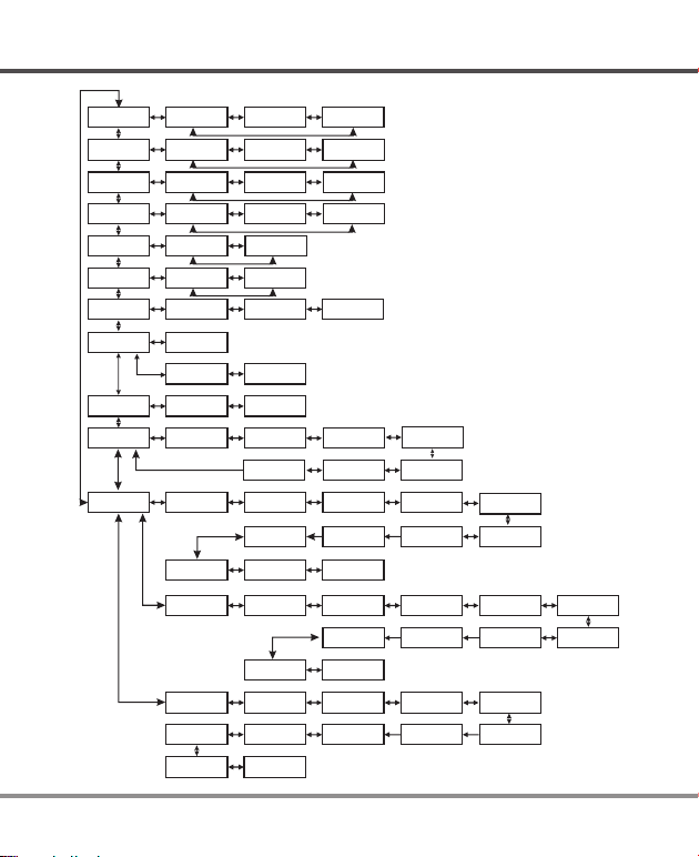
PROGRAM FLOW CHART
DECINC
BATT/PROGRAM
LiPo BATT
DECINC
BATT/PROGRAM
LiFe BATT
DECINC
BATT/PROGRAM
LiIo BATT
DECINC
BATT/PROGRAM
LiHV BATT
DECINC
BATT/PROGRAM
NiMH BATT
DECINC
BATT/PROGRAM
NiCd BATT
DECINC
BATT/PROGRAM
Pb BATT
DECINC
BATT/PROGRAM
BATT METER
DECINC
BATT/PROGRAM
BATT RESISTANCE
DECINC
BATT/PROGRAM
SYSTEM SETTING->
DECINC
BATT/PROGRAM
BATT MEMORY
ENTER
START
ENTER
START
START
ENTER
START
ENTER
START
ENTER
START
ENTER
START
ENTER
START
ENTER
START
ENTER
START
ENTER
START
ENTER
START
ENTER
START
ENTER
INC
LiPo BALANCE
2.0A 14.8V(4S)
LiFe BALANCE
2.0A 13.2V (4S)
Lilo BALANCE
2.0A 14.4V (4S)
LiHV BALANCE
2.0A 15.2V (4S)
NiMH CHARGE
CURRENT 2.0A
NiCd CHARGE
CURRENT 2.0A
Pb NORMAL CHG
2.0A 12.0V
0.000 V
0.000 V
3.722 V
0.000 V
5.1 3.0 mΩ
5.3 3.5 mΩ
Safety Timer
ON 120Min
[ BATT MEMORY 1 ]
ENTER SET->
STARG/ENTER>3 Seconds
LiPo BALANCE
2.0A 14.8V(4S)
[ BATT MEMORY 2 ]
ENTER SET->
[ BATT MEMORY 3 ]
ENTER SET->
Pb NORMAL CHG
2.0A 6.0v
Pb AGM CHG
2.0A 6.0V 2.0A 6.0V
LiPo CHARGE
2.0A 14.8V(4S)
DEC
INC
LiFe CHARGE
2.0A 13.2V (4S)
DEC
INC
Lilo CHARGE
2.0A 14.4V (4S)
DEC
INC
LiHV CHARGE
2.0A 15.2V (4S)
DEC
INC
NiMH RE-PEAK
1
DEC
INC
NiCd RE-PEAK
1
DEC
INC
Pb AGM CHG
2.0A 12.0V 2.0A 12.0V
DEC
0.000 V
(Connect the main battery socket)
0.000 V
INC
3.627 V
MAIN 7.35V
0.000 V
H3.724V L3.627V
DEC
INC
TOTAL: 16.8mΩ
DEC
INC
Capacity Cut-Off
ON 5000mAH
DEC
Stop
Version
Batt Type
HW:1.00 SW: 1.00
START
BATT TYPE
LiPo
ENTER
[ BATT MEMORY 1 ]
C:2.0A
INC
LiPo CHARGE
2.0A 14.8V(4S)
DEC
START
BATT TYPE
ENTER
STARG/ENTER>3 Seconds
NiMH CHARGE
CURRENT 2.0A
START
BATT TYPE
ENTER
INC
ENTER CHARGER
LOAD……
DEC
INC
Pb COLD CHG
DEC
INC
LiPo STORAGE
2.0A 14.8V(4S)
DEC
INC
LiFe STORAGE
2.0A 13.2V (4S)
DEC
INC
Lilo STORAGE
2.0A 14.4V (4S)
DEC
INC
LiHV STORAGE
2.0A 15.2V (4S)
DEC
INC
Pb COLD CHG
DEC
(Connect battery via balance board)
NiMH Sensitivity
D.Peak 4mV
Load Factory Set
BATT VOLTAGE
[ BATT MEMORY 1 ]
LiPo 14.8V (4S )
LiPo STORAGE
2.0A 14.8V(4S)
BATT VOLTAGE
9.6V(8S)
[ BATT MEMORY 2 ]
C:2.0A
NiMH RE-PEAK
1
BATT VOLTAGE
6.0V
[ BATT MEMORY 3 ]
C:2.0A
INC
DEC
INC
DEC
INC
DEC
INC
DEC
INC
DEC
INC
DEC
INC
ENTER
DEC
INC
14.8V ( 4S )
DEC
INC
DEC
INC
NiMH
DEC
INC
DEC
INC
Pb
DEC
STARG/ENTER>3 Seconds
NiCd Sensitivity
D.Peak
4mV
DECINC
Key Beep ON
Buzzer ON
CHARGE CURRENT
2.0A
SAVE PROGRAM
SAVE….
CHARGE CURRENT
2.0A
[ BATT MEMORY 2 ]
NiMH 9.6V (8S )
CHARGE CURRENT
2.0A
[ BATT MEMORY 3 ]
Pb 6.0V
START
TVC=YOUR RISK
4.20V
ENTER
START
SAVE PROGRAM
ENTER
ENTER
INC
TRICKLE
100mA
DEC
SAVE PROGRAM
SAVE….
INC
SAVE PROGRAM
DEC
SAVE PROGRAM
SAVE….
DECINC
DECINC
ENTER
INC
PEAK DELAY
1Min
DEC
START
SAVE PROGRAM
ENTER
DECINC
ENTER
· 08
T100
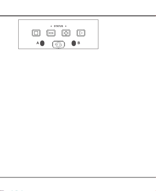
EXPLANATION OF BUTTONS
BATT/PROG
Stop
DEC INC
ENTER
Start
BATT PROG / STOP Button:
It is used to stop the progress or go back to previous step/screen
DEC Button:
It is used to go through the menus and decrease the parameter value
INC Button:
It is used to go through the menus and increase the parameter value
ENTER / START Button:
It is used to enter parameter or store parameter on screen.
CHANNEL Button:
It is used to switch from Channel A to B or vice versa.
When changing a parameter value in the program, press the START/ENTER button to
make it blink, then change the value by pressing the DEC and INC button. The value will
be stored by repressing the START/ENTER button. If there is a second parameter to edit
on the same screen, it will begin blinking after you confirm the first parameter value.
When starting the progress, press and hold the START/ENTER button for 3 seconds.
When stopping the progress or go back to previous step/screen, press the BATT
PROG/STOP button once.
When you first power the charger on it displays the last processes used. From here you
can change the battery type or press enter to change the charge process, charge current
rate and/or battery cell count, If you are charging a battery identical to the last one used
and want to perform the same process then simply press the start to begin that process.
T100
09 ·

BATTERY & POWER SUPPLY CONNECTIONS
Here is the detailed procedure to make the charger work. All the screens and
operations will take Li-Po BALANCE CHARGE program for example,
1. Connection
Connecting to power source
1).
It is an AC charger only.
Please insert the AC power cord to the wall socket (100-240V) directly to
power it on.
2).
Connecting the battery
The balance wire attached to the battery must be connected to the charger, with the
black wire aligned with the negative marking. Take care to maintain correct polarity.
(See the wiring diagram above) This diagram shows the correct way to connect your
battery to the SkyRC T100 when charging in the balance charge program mode.
Battery
Pack
· 10
TO AVOID SHORT CIRCUITS, ALWAYS CONNECT THE CHARGE
LEADS TO THE CHARGER FIRST, AND THEN TO THE BATTERY.
WARNING!
REVERSE THE SEQUENCE WHEN DISCONNECTING THE PACK.
T100

LITHIUM BATTERY PROGRAM (LIPO/LIFE/LILON/LIHV)
2. Getting started
It is highly recommended to have the flowchart handy while learning to operate this charger,
There are two main ways to setup the charger:
(1)Memory profile are available for setting and storing charge parameters for up to 10
different batteries. Once a battery's information is stored into memory, it will be retained until
changed again manually. Recalling a battery's memory number makes the charger instantly
ready to go!
(2)The other method is by manually setting up the charge process each time. The T100 is
capable of the following processes:
The following steps describe how to manual setup the T100
BA T T/ P RO G RA M
Li P o BA T T
STAR T/E NTER
Li P o BA L AN C E
2. 0 A 11 . 1V ( 3 S)
STAR T/E NTER
Li P o BA L AN C E
2. 0 A 11 . 1V ( 3 S)
STAR T/E NTER
Li P o BA L AN C E
2. 0 A 11 . 1V ( 3 S)
STAR T/E NTER
Li P o BA L AN C E
2. 0 A 11 .
STAR T/E NTER
> 3 Sec onds
BA T TE R Y CH E CK
...........
3. BATT/PROGRAM Select
Press INC and DEC to go through all the programs and
press START/ENTER to enter LiPo BATT Program.
4. Mode Select
Press INC and DEC to go through all the modes and press
START/ENTER to enter LiPo Balance Charge Mode.
5. Battery Setting
Press START/ENTER, the current value will start to blink,
press INC and DEC to change the value and press
START/ENTER to confirm your setting.
At the same time, the battery cells number will start to blink,
press INC and DEC to change the value and press
START/ENTER to confirm your setting.
6. Program Start
1V ( 3 S)
Press and hold START/ENTER for 3 seconds to start the
program.
The charger is detecting the battery cell.
R: 3 SE R S :3 S ER
CA N CE L (S T OP )
T100
R shows the number of cells detected by the charger and S
is the number of cells set by you at the previous screen. If
both numbers are not identical, press STOP to go back to
previous screen to recheck the number of cells of the battery
pack before going ahead.
11 ·

LITHIUM BATTERY PROGRAM (LIPO/LIFE/LILON/LIHV)
R: 3 SE R S :3 S ER
CO N FI R M( E NT E R)
STAR T/E NTER
91% 12..14V
1.5A 00 :: :50 1 2
25 % BA L
B:A:6.3V CHGNiM H
R shows the number of cells detected by the charger and S is
the number of cells set by you at the previous screen. If both
numbers are identical, press START/ENTER to start charging
process.
7.
Charging Status Monitor
During charge process,The real-time status will be shown on the screen.
If the user charge two batteries simultaneously, this will be started to
display after the twin-channels have been working for ten seconds.
And the user is only allowed to back to the working interface that started
lastly with START/ENTER and channel switch button.
VARIOUS I NFORMATION DURING THE PROCESS
Press INC or DEC during charging or discharging process allows the user to view
a variety of information on the LCD screen.
91% 12..14V
1.5A 00 :: :50 1 2
40 7 0 40 6 0 V
41 1 0
Li P o BA L AN C E
2. 0 A 11 . 1V ( 3 S)
Real-time status: battery icon, percentage of charge or discharge.
charge current, battery voltage, elapsed time and capacity.
INC
INC
DEC
Voltage of each cell in the battery pack when the battery is
0 V
connected with balance lead.
Final voltage when the program ends.
DEC
r
Safety timer ON and duration of time in minutes.
DEC
Capacity cut-off ON and the setting value of capacity.
· 12
T100

LITHIUM BATTERY PROGRAM (LIPO/LIFE/LILON/LIHV)
8. Program Stop
During the charging process, press STOP to stop the charging process.
9. Program Complete
When the charging process finishes, an audible sound will be heard.
Charging Program
Depends on different battery type, the operation programs are different.
Batt
Type
LiPo
LiHV
Lilon
LiFe
NiMH
NiCd
Pb
Video
Tutorial
Operation
Program
BALANCE
CHARGE
STORAGE
CHARGE
RE-PEAK
NORMAL CHG
AGM CHG
COLD CHG
This mode is for balancing the voltage of lithium-polymer battery cells while
charging.
This charging mode is for charging LiPo/LiHV/LiFe/LiIon battery in normal mode.
This program is for charging or discharging lithium battery which will not be
used for long time.
The charger will charge NiMH and NiCd batteries using the charge current
set by the user.
In re-peak charge mode, the charger can peak charge the battery once,
twice or three times in a row automatically. This is good for confirming the
battery is fully charged, and for checking how well the battery receives fast
charges.
This mode is for charging Pb battery.
This mode is for charging AGM battery.
This mode is for charging Pb battery in cold days when the temperature is
5
℃ to -20℃.
Please scan and watch the tutorial
video about how to charge LiPo
battery in balance mode.
Description
T100
13 ·

NIMH/NICD BATTERY PROGRAM
NiMH/NiCd:
This program is only suitable for charging NiMH/NiCd batteries. The T100 only offer Charge
and Re-Peak charge modes for NiMH/NiCd batteries.
Selecting the Battery Type:
After powering on the T100, press the INC or DEC button repeatedly until you reach the
appropriate program for the battery type you wish to charge. For this example we have
chosen the“NiMH BATT“ or“NiCd BATT”program. Now press the ENTER button to enter the
desired program.
BEFORE YOU BEGIN CHARGING YOUR BATTERY, MAKE SURE YOU
ARE CHARGING NIMH/NICD BATTERIES. CHARGING LIPO BATTERY
WARNING!
UNDER NIMH/ NICD BATTERY PROGRAM WILL CAUSE FIRE.
NiMH/NiCd Charge Mode:
BEFORE YOU BEGIN CHARGING YOUR BATTERY, MAKE SURE YOU HAVE
READ AND UNDE RS TO OD A LL O F THE WAR NI NGS AN D S AF ETY
INFORMATION CONTAINED ON PAGES 05-07.
After selecting the correct battery type, if the screen does not read “CHARGE”,
use the DEC or INC buttons to change it to the “CHARGE” mode.
NiMH CHARGE
CURRENT 2.0A
STAR T/ ENT ER
NiMH 2.0A 5.42V
CHG 002:22 00106
Press the ENTER button and the amp rate value will begin
blinking. Use the DEC or INC button to adjust the value to the
desired rate. Follow the instructions provided on your battery
when setting the charge current.
Press and hold the ENTER button for 3 seconds to start
charging.
Once charging has commenced, the charger will display the
following real-time information: battery type, charging current,
battery voltage, working mode, elapsed time and charged
capacity. Once the battery is fully charged, the screen will
read "FULL" and the charger will emit a ringing sound. You
can press the STOP button at any time during the charging
process to stop charging.
· 14
T100

NIMH/NICD BATTERY PROGRAM
NiMH/NiCd Re-Peak Mode:
Applicable to NiMH and NiCD batteries only, in re- peak mode the charger can peak
charge the battery once, twice, or three times in a row automatically. This process is
good for confirming that the battery is fully charged and for verifying how well the
battery can accept a fast charge. A five-minute cool-down delay occurs after each
re-peak charge.
IN RE-PEAK MODE, THE T100 USES THE CHARGE AMPERAGE AND VOLTAGE
SETTINGS ENTERED IN CHARGE MODE.
NiMH RE-PEAK
2
STAR T/ ENT ER
NiMH 1.3A 10.42V
RPC 004:04 00686
After selecting the correct battery type, use the INC or DEC
button to select the “RE-PEAK” mode. Press the START
button and the Re-peak cycle number 1 begins to flash on
the screen. Use the INC or DEC button to scroll through the
cycle count and set a number between 1 and 3.
Press and hold the START button for 3 seconds to start the
re-peak process.
Once the Re Peak process has begun, the charger will display
the following real-time information: battery type, charging
current, battery voltage,Working Mode, elapsed time and
charged capacity. Once the Re-P eak proceshas completed,
the screen will read "FULL”and the charger will emit a ringing
sound. The charger will display the charge/discharge capacity
for each cycle. Using the + and - buttons, you can scroll
through the history data of each cycle.
T100
15 ·

PB LEAD-ACID BATTERY PROGRAM
Additional NiMH/NiCd Process Information:
During the NiMH/NiCd battery charging process the T100 can display avariety of
information. Using the INC or DEC buttons, you can also view the following.
information:
NiMH Sensitivity
D.Peak 4mV/CELL
Safety Timer
ON 120min
Capacity Cut-Off
ON 5000mAh
Delta Peak Voltage
Sensitivity setting
Safety timer
setting
Capacity limit
setting
12.56V
Pb Lead-Acid Battery Program
Pb (Lead-Acid):
BATT/PROGRAM
Pb BATT
Pb Charge Mode:
After selecting the correct battery type, use the INC or DEC button to change it to the
“CHARGE“ mode.
Press the START button and the amp rate value will begin flashing. Use the INC or
DEC buttons to adjust the value to the desired charge rate. The amp rate should be
set to 1/10th of capacity. For example, if you are charging a 20Ah battery the charge
rate should be set to 2A. Follow the instructions provided on your battery when
setting the amp rate.
· 16
This program is only suitable for charging 6/12V Pb(lead-acid)
batteries which are significantly different from NiMH/NiCd
batteries. Pb batteries are suggested to charge with a low
current of 0.1C and cannot be used for fast charging. Please
follow the instructions provided by the battery manufacturer.
The T100 offers the following Pb charge modes: Charge, AGM
and COLD.
T100

PB LEAD-ACID BATTERY PROGRAM
Pb Charge
1.5A 12.0V(6P)
Press the START button again and the nominal battery pack
voltage will begin flashing. Use the INC or DEC button to set
the voltage and the number of cells.
Press and hold the START button for 3 seconds to start
charging.
P-6 1.5A 13.56V
CHG 002:22 00106
Once charging has commenced, the charger will display the
following real-time information: battery type, charging
current, battery voltage, working mode, elapsed time and
charged capacity.
When charging is complete, the screen will read “FULL ”
and the charger will emit a ringing sound.
Pb AGM Mode:
After selecting the correct battery type, use the INC or DEC button to change it to the
“AGM CHARGE“ mode.
Press the START button and the amp rate value will begin flashing. Use the INC or
DEC buttons to adjust the value to the desired charge rate. The amp rate should be
set to 1/10th of capacity. For example, if you are charging a 20Ah battery the charge
rate should be set to 2A. Follow the instructions provided on your battery when
setting the amp rate.
Pb AGM CHG
1.5A 12.0V(6P)
Press the START button again and the nominal battery pack
voltage will begin flashing. Use the INC or DEC button to set
the voltage and the number of cells.
Press and hold the START button for 3 seconds to start
charging.
P-6 1.5A 13.56V
CHG 002:22 00106
Once charging has commenced, the charger will display the
following real-time information: battery type, charging
current, battery voltage, working mode, elapsed time and
charged capacity.
When charging is complete, the screen will read “FULL”
and the charger will emit a ringing sound.
T100
17 ·

PB LEAD-ACID BATTERY PROGRAM
Pb Cold Mode:
Pb COLD CHG
1.5A 12.0V(6P)
P-6 1.5A 13.56V
CHG 002:22 00106
Press the START button again and the nominal battery pack
voltage will begin flashing. Use the INC or DEC button to set
the voltage and the number of cells.
Press and hold the START button for 3 seconds to start
charging.
Once charging has commenced, the charger will display the
following real-time information: battery type, charging
current, battery voltage, working mode, elapsed time and
charged capacity.
When charging is complete, the screen will read “FULL ”
and the charger will emit a ringing sound.
· 18
T100

BATTERY MEMORY SET AND CALL OUT
The charger can store up to 10 different charge profiles for your convenience, and the
stored profiles can be recalled quickly without having to go through the setup process.
When you are willing to alter the parameter value in the program, press START/ENTER
to make it blink then change the value with INC or DEC. The value will be stored by
pressing START/ENTER once.
Note: All following screen are taking 2S(7.4V) LiPo battery for example.
1. Battery Memory Set
[ BA T T ME M OR Y 1 ]
EN T ER S E T- >
STAR T/ ENT ER
BA T T TY P E
Li P o
DEC INC
BA T T VO L TS
7. 4 V ( 2S )
DEC INC
CH A RG E C UR R EN T
4. 9 A
DEC INC
TV C =Y O UR R I SK
4. 2 0V
DEC INC
SA V E PR O GR A M
EN T ER
STAR T/ ENT ER
Enter the battery memory program.
(10 different charge profiles can be stored).
Set the battery type(LiPo/LiHV/LiFe/LiIon/NiMH/NiCd/Pb).
Set the voltage and number of cells(2S-4S).
Set the charge current(0.1-6.0A).
Set the terminal voltage(4.18-4.25V).
Press ENTER to save program.
T100
19 ·

BATTERY MEMORY SET AND CALL OUT
SA V E PR O GR A M
SA V E .
[ BA T T ME M OR Y 1 ]
Li P o 7. 4 V (2 S )
[ BA T T ME M OR Y 1 ]
C: 4 .9 A
START/ENTER
>3
Li P o BA L AN C E
4. 9 A 7. 4 V( 2 S)
· 20
Seconds
Indicate the battery type and battery cell of the saved profile.
Indicate the charge current of the saved profile.
Press the START/ENTER for 3 seconds to call out the memory.
2. Battery Memory Call Out
Press START/ENTER for 3 seconds to start the process.
T100

SYSTEM SETTING
The system will be set to its default parameters when powered on for the first time. The
screen displays the following information in sequence and the user can change any given
value on each screen.
To change a parameter value in the program, press START/ENTER to make that value
blink. Next, change the value by pressing INC or DEC. The value will be stored by
pressing START/ENTER once.
ITEM SELECTION DESCRIPTION
When you start a charge process, the
integral safety timer automatically starts
Sa f et y T im e r
ON 1 2 0M i n
Ca p ac i ty C u t- O ff
ON 5 0 00 m AH
OFF/
ON
1-720 Min)
(
OFF/
ON
(
100-50000 mAh)
running at the same ti me. Th is is
programmed to prevent overcharge the
battery if it proves to be faulty, or if the
termination circuit cannot detect the
battery full. The value for the safety timer
should be generous enough to allow a full
charge of the battery.
This program sets the maximum charge
capacity that will be supplied to the
battery during charge. If the delta peak
voltage is not detected nor the safety
timer expired by any reason, this feature
will automatically stop the process at the
selected capacity value.
T100
21 ·

SYSTEM SETTING
ITEM SELECTION DESCRIPTION
Ni M H Se n si t iv i ty
D. P ea k
4 m V
Ni C d Se n si t iv i ty
D. P ea k
4 m V
Ke y B ee p O N
Bu z ze r O N
Default: 4mV/Cell
3-15mV/Cell
OFF/ON
This program is for NiMH/NiCd battery
only. When the charger detects the delta
peak value reaches the value you set, the
charger will say the battery is fully
charged.
The beep sounds at every time touching
the buttons to confirm your action. The
beep or melody sounded at various times
during operation to alert different mode
changes.
Lo a d Fa c to r y Se t
ENTER
Ve r si o n
HW : 1. 0 0 SW: 1 . 1 0
· 22
Press and hold the Start/ENTER button
to load the factory default settings.
It indicates the hardware and firmware
version.
T100

BATTERY METER
The user can check battery's total voltage, the highest voltage, the lowest voltage
and each cell's voltage.
Please connect the balance wire attached to the battery to the balance socket and
the XT60 male connector to the XT60 female connector in front of the charger.
Battery
Pack
This diagram shows
the correct way to
connect your battery
to check the voltage.
BA T T/ P RO G RA M
BA T T ME T ER
START
ENTE R
3.722 V 3.627 V
0.0 00 V 0. 00 0 V
INC
MA I N 16 . 76 V
H4 . 20 0 V L4 . 18 2 V
T100
Press the START/ENTER to enter the Lithium Battery
Meter program.
The display indicates each cell's voltage.
The display indicates the total voltage, the highest
and the lowest voltage.
23 ·

BATTERY RESISTANCE METER
The user can check battery's total resistance
Please connect the balance wire attached to the battery to the balance socket and
the XT60 male connector to the XT60 female connector in front of the charger.
and each cell's resistance.
Battery
Pack
This diagram shows
the correct way to
connect your battery to
check the resistance.
BA T T/ P RO G RA M
BA T T RE S IS T AN C E
Star t
Ente r
6.7 12.8
0.0 0.0 mΩ
INC
TO T AL : 19.5
Press the START/ENTER to enter the Lithium Battery
Resistance program.
mΩ
The display indicates each cell's resistance.
mΩ
The display indicates the total resistance.
· 24
T100

WARNING AND ERROR MESSAGE
In case of an error the screen will display the cause of error and emit an audible sound.
Incorrect polarity connected.
The battery is interrupted.
CO N NE C T ER R OR
CH E CK M A IN P O RT
BA L AN C E WIRES
NOT CONNECTED
IN T .T E MP . TO O H I
OV E R CH A RG E
CA P AC I TY L I MI T
OV E R TI M E LI M IT
CO N TR O L FA I L
CELL ERROR
T100
The battery connection is wrong.
The balance wires are not connected while charging in
balance mode.
The internal temperature of the unit goes too high.
The battery capacity is more than the maximum capacity
which the user sets.
The charging time is longer than the maximum charging
time which the user sets.
Voltage of the battery pack is lower than 5V. This charger
can not charge battery whose voltage under 5V.
The cell number is wrong.
25 ·

THE SET CONTAINS
THE SET CONTAINS
1. SkyRC T100 Charger
2. Power Cord
21
· 26
T100

SPECIFICATION
AC Input Voltage : 100-240V
Display Type: 2x16 LCD Display Backlight: Blue
Case Material: Plastic Controls: Five Buttons
Case Size: 100x90x127mm Weight: 500g
External Port: 2-4S Balance Socket-XH,
XT60 Female Connector.
Delta Peak Detection for NiMH/NiCd: 3-15mV/cell / Default: 4mV/cell
Charge Voltage: NiMH/NiCd: Delta peak detection
LiPo: 4.18-4.25V/cell
LiHV:4.25-4.35V/cell
LiFe: 3.58-3.7V/cell
LiIon: 4.08-4.2V/cell
Balance Current: 300mA/cell
Reading Voltage Range: 0.1-17.4V/cell
Battery Types/Cells: LiPo/LiHV/LiFe/LiIon: 2-4cells
NiMH/NiCd: 6-8cells
Pb: 6/12V
Battery Capacity Range: NiMH/NiCd: 100-50000mAh
LiPo/LiHV/LiFe/LiIon: 100-50000mAh
Pb: 100-50000mAh
Charge Current: 0.1A-5.0A
Safety Timer: 1-170minutes & OFF
Charge Wattage: 50Wx2 Max
Balance Cells: 2-4 cells
Memory: 10 different charge profiles
Charge Method: CC/CV for Lithium batteries.
Delta-peak Sensitivity for NiMH/NiCd batteries.
CC/CV and float charge for PB batteries.
T100
27 ·

CONFORMITY DECLARATION
SkyRC T100 satisfy all relevant and mandatory EC directives and FCC Part 15
Subpart B
EN 55014-1:2017
Electromagnetic
compatibility
EN 55014-2:2015
Electromagnetic
compatibility
EN 61000-3-2:2014
Electromagnetic
compatibility (EMC)
EN 61000-3-3:2013
Electromagnetic
compatibility (EMC)
EN 60335-2-29:2004+A2:2010+
A11:2018 to be used in conjunction
with EN 60335-1:2012+A11:2014+
A13:2017
IEC 60335-2-29:2002 (Fourth Edition)
+A1:2004 +A2:2009 for use in
conjunction with IEC 60335-1:2010
(Fifth Edition) +A1:2013
FCC Rules Part 15 Subpart B
Requirements for Household Appliances, electric
tools, and similar apparatus –Part 1: Emission
Requirements for Household Appliances, electric
tools, and similar apparatus – Part 2: ImmunityProduct family standard
Part 3-2: Limits-Limits for harmonic current
emissions (equipment input current up to and
including 16 A per phase
Part 3-3: Limits - Limitation of voltage changes,
voltage fluctuations and flicker in public low-voltage
supply systems, for equipment with rated current ≤ 16
A per phase and not subject to conditional connection
Safety of household and similar
electrical applicances
Safety of household and similar
electrical appliances Particular
requirements for battery chargers
Unintentional Radiators
· 28
T100

REGULATORY INFORMATION
This symbol means that you must dispose of electrical from the General household
waste when it reaches the end of its useful life. Take your charger to your local waste
collection point or recycling centre. This applies to all countries of the European
Union, and to other European countries with a separate waste collection system.
FCC Note:
This device complies with Part 15 of the FCC rules. Operation is subject to the
following two conditions:
(1) this device may not cause harmful interference, and (2) this device must accept
any interference received, including interference that may cause undesired
operation.
The manufacturer is not responsible for any radio or TV interference caused by
unauthorized modifications or change to this equipment. Such modifications or
change could void the user's authority to operate the equipment.
This equipment has been tested and found to comply with the limits for a Class B
digital device, pursuant to part 15 of the FCC Rules. These limits are designed to
provide reasonable protection against harmful interference in a residential
installation. This equipment generates, uses and can radiate radio frequency energy
and, if not installed and used in accordance with the instructions, may cause harmful
interference to radio communications. However, there is no guarantee that
interference will not occur in a particular installation. If this equipment does cause
harmful interference to radio or television reception, which can be determined by
turning the equipment off and on, the user is encouraged to try to correct the
interference by one or more of the following measures:
– Reorient or relocate the receiving antenna.
– Increase the separation between the equipment and receiver.
– Connect the equipment into an outlet on a circuit different from that to which the
receiver is connected.
– Consult the dealer or an experienced radio/TV technician for help.
To maintain compliance with FCC's RF exposure guidelines, this equipment should
be installed and operated with a minimum distance of 20cm between the radiator
and your body.
T100
29 ·

COMMONLY USED TERMS
Commonly used terms
Final charge voltage: the voltage at which the battery's charge limit (capacity limit)
is reached. The charge process switches from a high current to a low maintenance
rate (trickle charge) at this point. From this point on further high current charging
would cause overheating and eventual terminal damage to the pack.
Final discharge voltage: the voltage at which the battery's discharge limit is
reached. The chemical composition of the batteries determines the level of this
voltage. Below this voltage the battery enters the deep discharge zone. Individual
cells within the pack may become reverse polarized in this condition, and this can
cause permanent damage.
A, mA: unit of measurement relating to charge or discharge current.1000 mA = 1 A
(A=Ampere,mA=Milliampere)
Ah, mAh: unit of measurement for the capacity of a battery (Amperes x time unit; h
= hour). If a pack is charged for one hour at a current of 2 A, it has been fed 2 Ah of
energy. It receives the same quantity of charge (2 Ah) if it is charged for 4 hours at
0.5 A, or 15 minutes (=1/4 h) at 8 A.
'C'-rating: Capacity is also referred to as the 'C' rating. Some battery suppliers
recommend charge and discharge currents based on the battery 'C' rating. A
battery's '1C' current is the same number as the battery's rated capacity number, but
noted in mA or amps. A 600mAh battery has a 1C current value of 600mA, and a 3C
current value of (3 x 600mA) 1800mA or 1.8A. The 1C current value for a 3200mAh
battery would be 3200mA (3.2A).
Nominal voltage(V): The nominal voltage of the battery pack can be determined as
follows;
-.NiCd or NiMH: multiply the total number of cells in the pack by 1.2. A 8-cell pack
will have a nominal voltage of 9.6 volts (8x1.2).
-.LiPo: multiply the total number of cells in the pack by 3.7. A 3-cell LiPo wired in
series will have a nominal voltage of 11.1 volts (3x3.7).
-.LiIo: multiply the total number of cells in the pack by 3.6. A 2-cell LiIo wired in series
will have a nominal voltage of 7.2 volts (2x3.6).
-.LiFe: multiply the total number of cells in the pack by 3.3. A 4-cell LiIo wired in
series will have a nominal voltage of 13.2 volts (4x3.3).
If the nominal voltage of the battery is not printed on the battery's label, consult your
battery manufacturer or supplier. Do not guess the rated voltage of battery.
· 30
T100

WARRANTY AND SERVICE
Liability exclusion
This charger is designed and approved exclusively for use with the types of battery
stated in this Instruction Manual. SkyRC accepts no liability of any kind if the charger
is used for any purpose other than that stated.
We are unable to ensure that you follow the instructions supplied with the charger,
and we have no control over the methods you employ for using, operating and
maintaining the device. For this reason we are obliged to deny all liability for loss,
damage or costs which are incurred due to the incompetent or incorrect use and
operation of our products, or which are connected with such operation in any
way.Unless otherwise prescribed by law, our obligation to pay compensation,
regardless of the legal argument employed, is limited to the invoice value of those
SkyRC products which were immediately and directly involved in the event in which
the damage occurred.
Warranty and service
We guarantee this product to be free of manufacturing and assembly defects for a
period of one year from the time of purchase. The warranty only applies to material or
operational defects, which are present at the time of purchase. During that period, we
will repair or replace free of service charge for products deemed defective due to those
causes.
This warranty is not valid for any damage or subsequent damage arising as a
misuse, modification or as a result of failure to observe the procedures outlined in this
manual.
result of
Note:
1.
The warranty service is valid in China only.
If you need warranty service overseas, please contact your dealer in the first
2.
instance, who is responsible for processing guarantee claims overseas. Due to
high shipping cost, complicated custom clearance procedures to send back to
China. Please understand SkyRC can't provide warranty service to overseas
end user directly.
If you have any questions which are not mentioned in the manual, please feel
3.
free to send email to info@skyrc.cn
T100
31 ·

This content is subject to change.
Latest version can be downloaded
from www.skyrc.com
If you have any question about this document, please contact
SkyRC by sending a message to info@skyrc.cn
All Rights Reserved.
All specifications and figures are subject to change without notice.
Printed in China 2019.09
7502-1254-01
 Loading...