

Page 1
INSTRUCTION MANUAL
120
DAYS
1/12 & 1/10 SCALE ADVANCE
RACING SPEED CONTROLLER
Support Both Sensor or Sensor-less Brushless Motor
PLEASE READ ALL INSTRUCTIONS BEFORE OPERATION
INTRODUCTION
SkyRC introduces the economical, easy to use Toro 1 cell Brushless System. This ESC comes
with built-in DC/DC inverter (DC/DC booster) and DC/DC converter. This innovative technology
allows drivers to power their vehicle’s electronics on a single 1 cell Li-Po battery pack without
installing additional external boosters or receiver pack and also the ESC can be powered by 2
cells Li-Po without external BEC.
Toro 1 cell ESC is also compatible with all sensorless brushless motors and most sensored
brushless motors with timing or without timing.
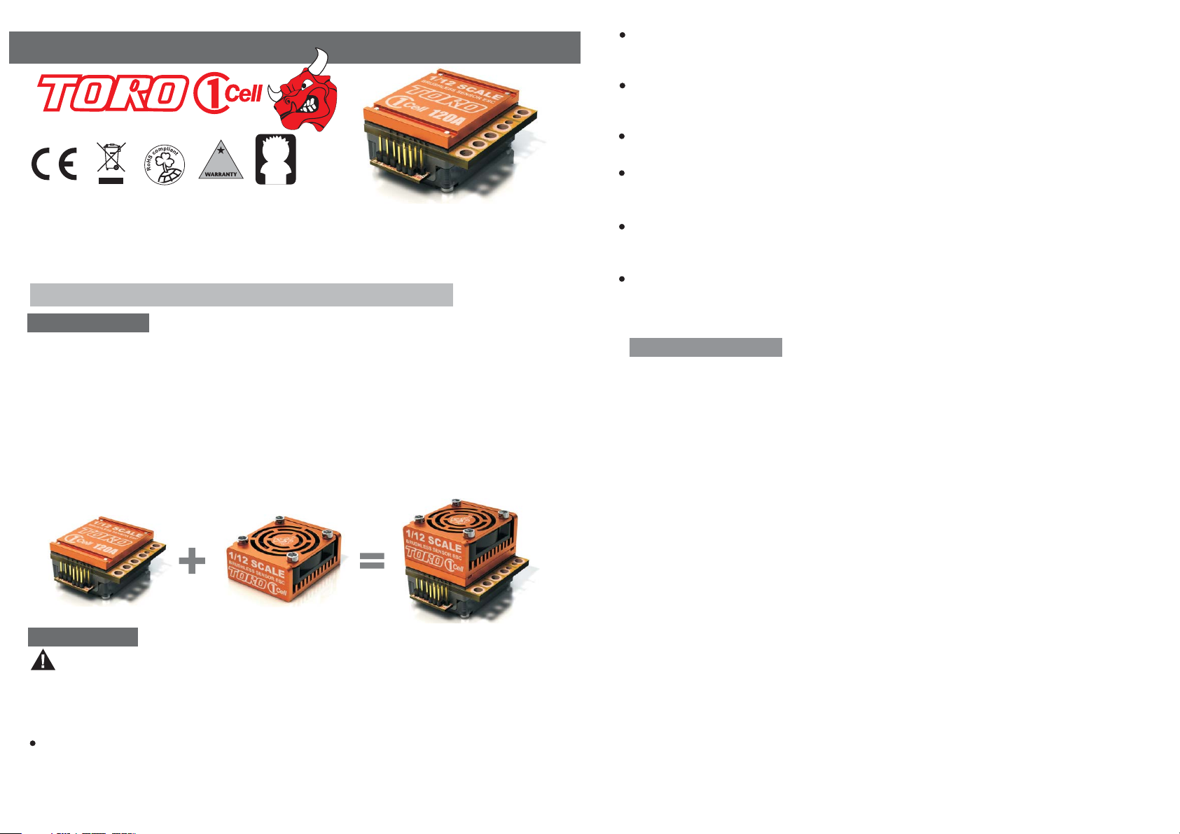
Toro 1 cell ESC is optimized for 1 cell racing and features a low-profile heat sink for easy
installation in 1/12 scale vehicles with space constraints.
This ESC also comes with a cooling system to support 2S LiPo, 1/10 scale vehicle. You can
use thermal double-sided adhesive tape(included) to mount the cooling system on top of ESC.
+Yr
14
NO REVERSE VOLTAGE!
Reverse battery polarity can damage ESC & void warranty. Disconnect battery immediately
if a reverse connection occurs.
DISCONNECT BATTERIES WHEN NOT IN USE
Always disconnect the battery pack from the speed control when not in use to avoid short
circuits and possible fire hazard.
TRANSMITTER ON FIRST
Turn on the transmitter first THEN turn on the speed control.
INSULATE WIRES
Always insulate exposed wiring with heat shrink tubing or electrical tape to prevent short
circuits, which can damage ESC.
TIMING PRODUCES DANGEROUSLY HIGH SPEED
When Toro's electronic motor timing is enabled, the vehicle speed can be increased
dramatically. Please take extra precautions.
TIMING INCREASE ESC & MOTOR'S TEMPERATURE.
Electronic motor timing will increase the temperatures of ESC and brushless motor. Use
extreme caution when setting up and testing your application to avoid overloading
and overheating.
BEFORE YOU BEGIN
1)Plan Speed Control Placement
Choose a location for the speed control that is protected from debris. To prevent radio
interference place the speed control as far away from the radio receiver as possible
and keep the power wires as short as possible.Select a location that has good airflow
ventilating. If the ESC gets air flow, it will run cooler; and that means, it will be
more efficient.
2)Mount Speed Control in Vehicle
Use double-sided tape to mount the speed control in vehicle(do not use CA glue).
Secure power capacitor module to chassis. Yo u can use double-sides tape or a
tie wrap to mount power capacitor to the vehicle's chassis or shock tower. Module
can also be tie-wrapped along the power wires.
Use double-sided tape to mount the switch where it will be easy to access.Select
a position where it will not get damaged or get switched OFF
roll-over.
during a crash or
TORO 1 Cell ESC Cooling System
SAFETY NOTE
WARNING: This is an extremely powerful brushless motor system. We strongly
recommend removing your pinion gear for your own safety and the safety of those around
you before performing calibration and programming functions with this system. Please keep
your hands, hair, cloth, clear from the gear train and wheels of an armed high performance
system.
WATER & ELECTRONICS DON'T MIX!
Never allow water, moisture, or other foreign materials to get inside ESC, motor, or on the
PC Boards. Water damage will void the warranty!
1/8
Ver. 1.1
3) Soldering
Cut the ESC's BLUE, YELLOW & ORANGE silicone motor power wires to the desired
length and strip about 3.2mm-6.35mm (1/8”-1/4”) of insulation from the end of each
wire. “Pre-tin”the wire by heating the end and applying solder until it is thoroughly
covered.
CAUTION: By very careful not to splash yourself with hot solder.
Place the ESC's BLUE Phase ‘A’ motor wire onto motor's ‘A’
Use soldering iron to apply heat to exposed wire; begin adding solder to tip of soldering
iron and wire. Add just enough solder to form a clean and continuous joint from the
plated area of the solder tab up onto the wire. Solder the ECS's YELLOW Phase
‘B’ motor wire to the motor's ‘B' solder tab and Solder the ESC's ORANGE
Phase ‘C' motor wire to motor’s ‘C’ solder tab.
2/8
solder tab and solder.
Ver. 1.1
Page 2
CONNECTIONS
Connect motor sensor harness to ESC. Insert the 6 p in con nect or on th e end of
the mot or's s enso r wire s into E SC's s enso r harn ess so cket.
Connect ON/OFF switch to power output pins.
Connect Throttle lead to ESC and other end to the Receiver (Throttle Channel, Ch2)
Connect ESC to battery pack
ESC ON /O FF
switch
Throttle lead
Red LED blinks whiles beeping, indicating it's time to push full
brake . Move t hrot tle tr igge r to ful l brak e and wa it few seconds,
the ESC w ill bl ink re d LED an d ring s 1sec ond in dica ting f ull br ake
measure.
Yellow LED blinks whiles beeping, indicating it's time for neutral.
Relax t rigg er to ne utra l (cen ter) . The E SC wil l now ri ng 1 sec ond
and fla sh the y ello w LED ra pidl y to acc ept th e neut ral po siti on.
ESC wil l blin k LED an d ring o ne sec ond in dica ting t hat it i s armed.
Rece iv er
Sensor
harness
TORO
Sensor-based
Brushless motor
(540-class)
Switch
output
pins
Blue m ot or
phase wires
(phaseA)
Orange motor
phase wires
(phaseC)
Fan
output
pins
Yell ow m ot or
phase wires
(phaseB)
Black power wire
(battery negative)
SKYLink
interface pins
One cell battery pack
Power capacitor
Battery connector
Red po we r wi re
(battery positive)
1S Li- Po b at te ry
SKYLink interface pins allows you to connect the Program Card and SKYLink Interface
Adaptor to you ESC directly for easy programming.
ESC/TRANSMITER CALIBRATION
IMPORTAN T NOT E: Cal ibra tion i s nece ssar y for th e first use of the ESC, or whenever
used wi th a new/different transmitter.
For use rs wit h a Futa ba Tran smit ter, yo u must r ever se the throttle channel signal on
your tr ansm itte r. Plea se ref er to yo ur Fut aba in structions.
Individual transmitter's signals for full throttle, full brake and n eutr al var y. You mus t
calibrate your ESC so that it will operate more effectively with you r tran smit ter.
How to Ca libr ate ES C
ESC swi tch OF F.
Tur n on the Tr ansm itte r.
Hold fu ll thr ottl e on you r tran smit ter an d turn t he ESC's switch ON.
Keep holding full throttle on the transmitter. The ESC will flashes
LED and ring the initialization tones.
Wai t 2 seconds
Green LED blinks rapidly and the motor will rings 1 sec ond in dica ting
full throttle measured.
3/8 4/8
Ver. 1.1 Ver. 1.1
From this point on, when you connect batteries and turn on the switch, the ESC will give the
initialization tone and flash, and the arming tone will ring second or two later. If the ESC is
programmed for the Auto-Lipo setting, it will beep the number of cells in you Lipo pack
between the initialization tones and the arming tones. After the arming tone plays, the ESC will
ACTIVE and will respond to the throttle application.
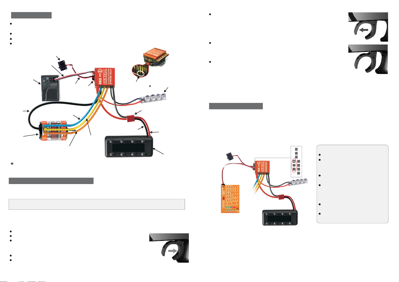
ESC PROGRAMMING
1)Programming Card(Optional Part)
Programming Card allows you to modify the most commonly used settings in your TORO 1
cell controller all at the touch of a single button. No computer needed. Simply connect the
Programming Card to the SKYLink interface pins of the controller and power the programming
card as described below. Click the button to scroll through and change the indicated
settings. All the settings will show on the programming card at once. Can't get any easier!
Instruction for Program Card
Instruction for Program Card
Turn off the ESC.
Connect the lead from program card
SKYLink
interface Pins
One cell battery pack
+
S
2)SKYLink Programming Interface(Optional Part)
Optional fully adjustable PC interface,which includes a USB cord and USB Interface
3)Manual Programming
Manua l Prog ramm ing TORO 1 c ell is a s simp le as an swer ing a fe w questions. The
TORO 1 cell a sks qu esti ng by be epin g a sett ing nu mber, f ollo wed by the possible
setti ng val ues. Ther e are ei ght se ttin gs tha t can be p rogrammed in the TORO .
to the SKYLink interface pins of
the controller.
Turn on the ESC to apply power to
both ESC and Program Card.
All the current settings will be
displayed on the correspond LEDs.
Press and release button to move
between settings.
Press and hold button to change the
value for that setting.
Turn off the ESC and disconnect lead
from Program Card.
Page 3

Programmable Features
Question (Setting)
1)Reverse Lockout(D)*
1)Disable
2)Normal(D)*
Note: Factory Defaults are indicated by asterisk (D)*
2)50%(D)*
1)25%
2)50%(D)*
2)Medium
4)Lowest(D)*
5)Disable
1)Disable(D)*
1)Large
2)Normal(D)*
3)Small
4)Very Small
5)Smallest
You must answer yes or no to the setting values as they are presented by TORO 1 cell.
"" ""
When you enter programming mode the ESC will emit a sequence of beeps and LED flashes
that tell you which programming step you are in. There are two parts to the beep sequence.
The first set of beeps indicates the 'Setting Number (Question), e.g. Brake/Reverse Type, and
the second set of beeps indicates a Setting Value, e.g. Reverse Lockout. Answering "No" to a
Setting value will cause the ESC to ask for the next value in that section. After a "Yes" answer
is accepted, the ESC knows you aren't interested in any other option in that section, so it skips
to the first option in the next section.
Note: I f you an swer " no" to a ll Set ting Value s for a pa rtic ular Setting Number, the ESC
will ke ep wha teve r valu e had be en pre viou sly pr ogra mmed . Only by answering "Yes" to
a Setti ng Val ue wil l the ES C stor e/ch ange t hat va lue.
How to Enter Programming Mode
Plug Battery into the TORO 1 cell
Hold full throttle on your transmitter
Turn the ESC switch ON
TORO 1 cell flashes LED and rings once
Wait few seconds.
TORO 1 cell flashes LED and rings 1 second indicating that it is ready for CALIBRATION mode
Continue to hold full throttle
TORO 1 cell flashes LED while beeping
Wait another few seconds
TORO 1 cell flashes LED and rings 1 second
TORO 1 cell flashes LED while beeping indication that you are in PROGRAMMING mode
Let trigger go neutral (Centre)
At this p oint t he TORO 1 ce ll wil l be fla shin g/be epin g the fo llowing sequence:
Beep-Pause-Beep... and then repeats
This in dica tes th at you a re at Qu esti on 1 and i t is ask ing to accept/reject value 1.
2)Auto-Lipo(D)*
When answering a question, you will need to move the trigger to yes (full throttle) position or
the no (full brake) position and keep it there for about 3 seconds. When the ESC has accepted
your answer it will confirm your reply by flashing the LED and emitting a beeping tone.
Release the trigger allowing it to go to Neutral to confirm that you are ready for ESC to ask
you next question. You are not required to continue through all eight programming options. For
example, if you wish only to change the Brake/Reverse Type (Option 1) then after
programming that setting you can disconnect power from the ESC and you're ready to run.
Disconnecting the controller in the middle of programming simply retains the values for the
remaining programming options that were previously set up.
5/8 6/8
Ver. 1.1 Ver. 1.1
Page 4

TIMING I NDICATOR L ED
To conform to ROAR's Sportsman Class racing rules and help race organizers monitor driver
compliance in non-timing race classes, Toro 1 cell ESC has included a feature in this speed
control that indicates when the ESC has its electronic motor timing advancement feature
activated.
At all times when the speed control is powered ON and the Dynamic Motor Timing is turned
ON and set to a level greater than zero timing advance, the ESC's white status LED will be
illuminated during normal operation.
SPEED CONTROL SPECIFICATION
Controls,TORO 1/12 1/10 Scale
Input Power(Cells)
Motor Type
1 LiPo or
Motor Limits,
3-4 NiMH
2 LiPo or
5-6 NiMH
BEC Output
(Support 1S & 2S LiPo)
Status LED(2 LEDs)
Thermal Overload Protection
Compatibility
Dimensions(Without fan)
Weight (Without wires)
Fwd/Brk or Fwd/Rev
1-2S LiP o/LiFe, 3-6 NiMH (8. 4V Max)
Sensored and sensorless Brushless Motors
≥3.5T(1/12 on-road)
≥4.5T(1/10 on-road),≥6.5T(1/10 off-road)
6.0Volts, 1Amp,built-in BEC with step-up
DC/DC booster for 1 cell LiP o racin g
White LE D, 3 Color LED(Red, Green
& Orange)
Yes
Sensored Brushless Motor or
Sensorless Brushless Motor
36.5X42X18mm (1.44X1.65X0.71in)
34g (1.20oz)
TROUBLE SHOOTING
Problem: My TOR O ESC ma y or may n ot arm , but it w ill no t cali brat e to my transmitter
Solution: Most ca libr atio n issu es can b e solv ed by ch angi ng settings on the transmit ter.
Make su re you h ave bo th you r thro ttle a nd bra ke endpoints (called EPA or
ATV on your radio) on the thro ttle c hann el out t o betw een 10 0 to 120 %. Mak e
sure if y ou hav e a Futa ba or Fu taba m ade tr ansmitter to have the throt tle
channel set to the reversed position.
Problem: My ESC ca libr ates f or the f ull th rott le and f ull br ake positions but won't
calibrate to the neutral throttle position. (Orange LED keeps flashing)
Solution: Try moving the throttle trim one way, then the ot her (usu all y towards the
thro ttl e sid e is best). If your transmitter has a 50/50 and 7 0/3 0 set tin g for the
thro ttl e, se t it for 50/50 and retry calibration. Also, if you have changed the
dead band to a narrower band you may wan t to try going back to the "normal"
sett ing.
Problem: Spee d Con tro l Run s Exc ess ive ly Ho t
Solution: Reduce timing level setting in ESC. Electro nic moto r timing set too high.
Incr eas e gea r rat io/ Red uce pini on.
7/8 8/8
Ver. 1.1 Ver. 1.1
Problem: My vehicle acts like it has "turbo lag" (poor acceleration/punch fo r the firs t
few feet or yards)
Solution: Make s ure you' re using high quality batteries and a battery connector capable
of high amp flow (40-100 amps). This behavior is very typical of a battery pack
that is having diffic ult y pro viding the power your vehicle/system requires for
top performa nce . Use copper bars to connect cells rather than welded tabs.
Copp er ba rs have a much lower resistance.
Problem: My bat ter y pac k is plugged into the ESC and nothing is wor kin g
Solution: Make sure the ESC's receiver plug is plugged into channel 2 on the receiver,
and that it's plugged in with the correct orientation. Double check your solder
conn ect ions on th e batter y plug, and make sure the battery is showing good
volt age .
Problem: Timing Does Not Operate Properly
Solution: Set motor rotation to counter-clockwise–Electronic motor timing advancement
only functio ns in counter -cl ock wise rot ation di rection. You may solve this
prob lem b y disabl e motor timing.
Problem: The ESC shut off and red LED flas hing
Solution: The ES C has buil t in thermal protection circu itr y to protect the ESC from
bein g dam age d dur ing running. If the thermal protection shuts the ESC off, the
redLED will flashing. Check the KV value of motor and make sure the pinion is
not too large for the motor. On ce th e ESC cool down, it will resume working.
PRODUCT WARRANTY
The TORO 1 cell Brushless ESC is guaranteed to be free from defects in materials or
workmanship for a period of 120 DAYS from the original date of purchase (verified by dated,
itemized sales receipt). Warranty does not cover incorrect installation, components worn by
use, damage to case or exposed circuit boards, damage due to timing, damage from using
more than 3 Li-Po cells input voltage, cross-connection of battery/motor power wires,
overheating solder tabs, reverse voltage application, improper use or installation of external
BEC, damage resulting from thermal overload or short-circuiting motor, damage from incorrect
installation of FET servo or receiver battery pack, tampering with internal electronics, allowing
water, moisture, or any other foreign material to enter ESC or get onto the PC board, incorrect
installation/wiring of input plug plastic, allowing exposed wiring or solder tabs to short-circuit,
or any damage caused by a crash, flooding or natural disaster. Because SKYRC has no
control over the connection & use of the speed control or other related electronics, no liability
may be assumed nor will be accepted for any damage resulting from the use of this product.
Every SKYRC speed control & motor is thoroughly tested & cycled before leaving our facility
and is, therefore, considered operational. By the act of connecting/operating speed control,
user accepts all resulting liability. In no case shall our liability exceed the product's original
cost. We reserve the right to modify warranty provisions without notice. This product is not
intended for use by children under 14 years of age without the strict supervision of an adult.
Use of this product in an uncontrolled manner may result in physical damage or injurise take
extra care when operating any remote control vehicle.
SPECI FICATION S AR E SUBJ ECT TO CHAN GE WIT HOUT NOTICE.
Manufactured by
SKYRC TECHNOLOGY CO., LTD.
www.skyrc.com
2011 SkyRC Technology Co., Ltd. All Rights Reserved.
7504-0201-02
 Loading...