

Page 1

Universal Battery Charger & Analyzer
NiMH / NiCd / NiZn / Eneloop / RAM / Lithium-Ion / LiIo4.35 / LiFePO4 / LTO
Instruction Manual
This content is subject to change.
Latest version can be downloaded
from www.skyrc.com
If you have any question about this document, please contact
SkyRC by sending a message to info@skyrc.cn
All Rights Reserved.
Manufactured by
SKYRC TECHNOLOGY CO., LTD.
www.skyrc.com
2018 SkyRC Technology Co., Ltd. All Rights Reserved.
[Version 1.14]
7504-0680-05
RoHS
Page 2
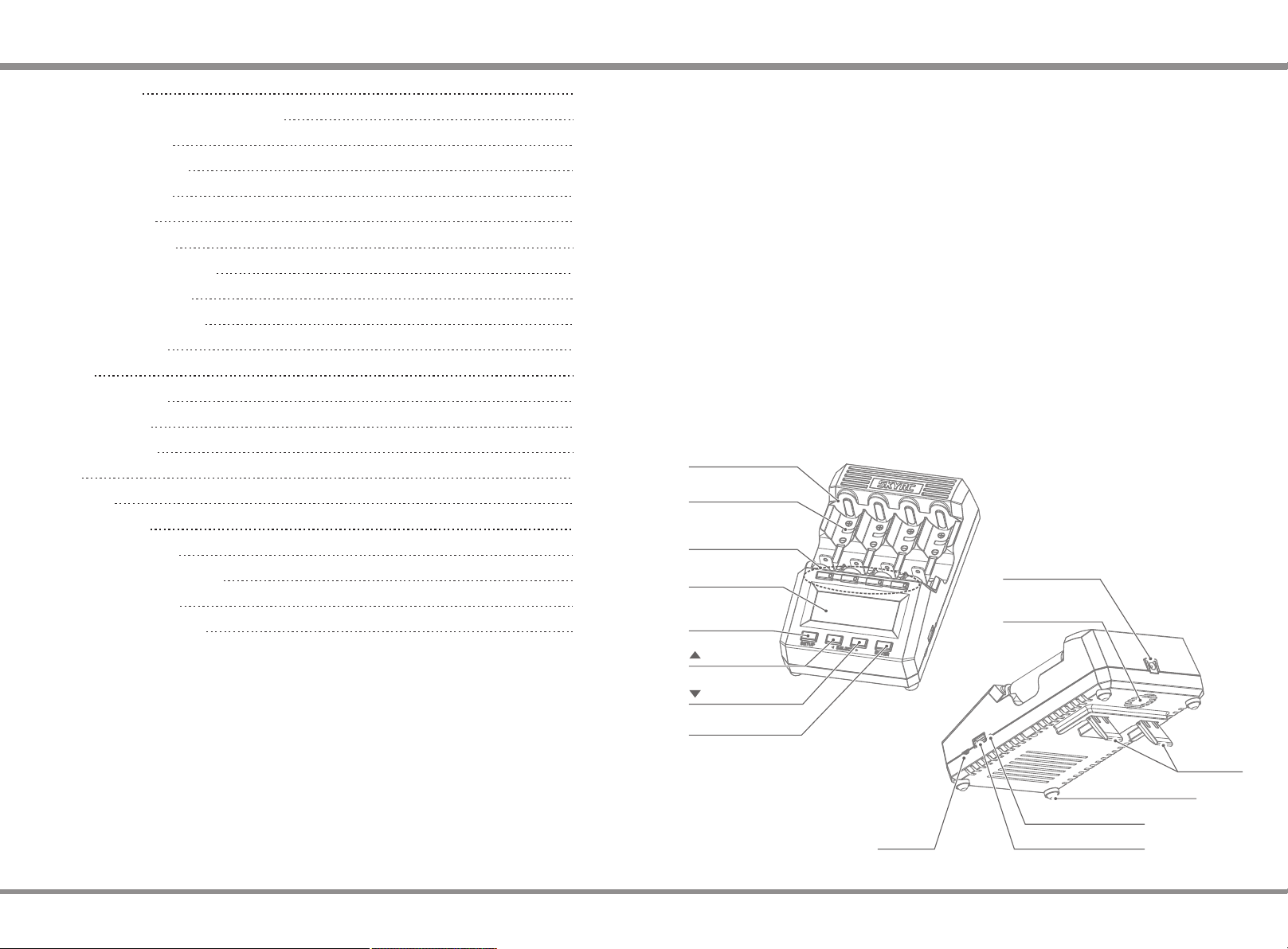
TABLE OF CONTENTS INTRODUCTION
INTRODUCTION
WARNING AND SAFETY PRECAUTIONS
QUICK START GUIDE
BATTERY KNOWLEDGE
BATTERY VOLTAGES
TOTAL OVERVIEW
GLOBAL SETUP VIEW
SLOT PROGRAMMING VIEW
SLOT OPERATION VIEW
DIAGRAM DRAWING VIEW
USER CALIBRATION
PC LINK
FIRMWARE UPDATE
BLUETOOTH APP
ERROR MESSAGE
FAQ'S
GLOSSARY
SPECIFICATIONS
PACKAGE CONTENTS
CONFORMITY DECLARATION
LIABILITY EXCLUSION
WARRANTY AND SERVICE
01
03
04
10
11
12
14
17
24
27
28
30
31
32
35
36
37
38
39
40
41
41
Welcome
Charging batteries is usually a primitive, boring task. Can’t fool your friends, it still is. In fact, this
charger merely knows three elementary routines: charge, discharge, rest. However ... refining,
combining, and repeating them in impressive cycles will make you feel dominant and superior! We
hope that operating the device will bring albeit unconsciously some fun and satisfaction to an
otherwise mundane activity: charging one's empty batteries. The MC3000 may be the most joyful
not so compact 4-bay universal round battery charger in the world. Maybe. The creation of this
product didn't arise out of need but from the desire to finally have a charger as versatile, accurate
and powerful as a SKYRC hobby charger but tailored to a sweet battery tray for cylindrical single
cell batteries; no more hassle with battery holders, fiddly wiring, clamps or similar DIY solutions.
With the agreeable set of options per program, or by sequencing several such programs, the
MC3000 is capable of mimicking virtually any operation mode recommended by leading battery
manufacturers or employed by other commercial chargers.
Features
The charger supports all common round battery sizes and chemistries in 4 independent slots, has
numerous safety mechanisms to protect user, device, and batteries from harm, offers maximum
charge rate of 3A/slot, true constant current for both charging and discharging, analyzing
capability, PC & Bluetooth 4.0 monitor & control, user calibration, high accuracy and an intuitive
user interface, while the updatable firmware ensures flexibility to respond to user demands and
future market or technology changes.
Battery Bays
Temp. Sensor
Slot Number
Button (SNB)
LCD Display
SETUP/STOP
Button
12-18V DC Plug
Smart
Ventilation Fan
UP Button
DOWN Button
ENTER Button
MC3000
PC Link
TiltStand
Anti Skid Rubber
Bluetooth Indicator
USB Power 5V/2.1A
01 ·
Page 3
INTRODUCTION
WARNING AND SAFETY PRECAUTIONS
User Interface
The UI can be switched between Dummy, Simple and Advanced menu modes. The advanced menu
lets the user control every single technical parameter of the operation mode whereas a simpler
mode with less options may be more convenient for quick everyday usage. The key concept behind
the UI are the numbered user programs: the MC3000 comes with 30 editable programs and
whenever the user is operating a slot, he/she is indeed operating a particular numbered program in
that slot and therefore should be well aware of the program number itself! The 30 programs are
defined globally: any ready slot can run the identical program simply by the user assigning the same
program number to the slot. And that is done fast and efficiently.
Slot Number Buttons
Integral part of the UI are the bi-color LEDs of the slot number buttons indicating one of the 6
possible operational states of a slot. An empty slot (=black SNB) is a slot with no battery in it, a
ready slot (=blinking red-green SNB) is ready to start the program, a busy slot (=solid red SNB) is
running a program, a finished slot (=solid green SNB) has finished a program normally. An inactive
slot is an empty or ready slot, an active slot is a busy or finished slot. A blinking red SNB indicates
an error, abnormal program termination, or similar. A blinking green SNB means happiness.
Control Buttons
The STOP button at the bottom left has similar meanings in different contexts. It can mean Cancel,
Discard, Abort, Quit or Exit when programming inactive slots, or Finish or Stop when operating
active slots. It is also the button for accessing the device SETUP. The ENTER button at the bottom
right means Enter, Next, or Save when programming inactive slots, Start for starting ready slots, or
Return to the main view when operating active slots. The UP and DOWN buttons mean Up and
Down, or Increase and Decrease, and are for changing program numbers, scrolling through options
or graphs, selecting parameters. Changing the program number means effectively that you switched
to the new program with the new program number and not only changed the number itself. For faster
programming, a changed program can be saved under a new program number, or copied over to all
slots at once.
Screen
The 128×64 LCD screen features five common views which the user should be familiar with:
The total overview (TOV) is the main view where other views automatically revert to after periods
of user inactivity. In tabular format, it shows at a glance the most important bits of information
about the operation of the slots. TOV is also used for displaying quick info lines or error
messages, for example at abnormal program termination.
The MC3000 has numerous explicit options with their respective parameters which the user can
check or control. The more general settings are accessible through SETUP in the global setup
view (GSV). They affect the operation of the entire device, not only of a single slot or program.
In slot programming view (SPV) the user can either swiftly change the program to a different
program and or edit its detailed settings. Each of the four slots is independent and can run any of
the 30 global programs.
Naturally the slot operation view (SOV) is available for active slots only, i.e. slots with an ongoing
or finished program. Apart from the most basic info already given in TOV, it also shows additional
quantities such as energy, power, resistance, temperature, and time.
The diagram drawing view (DDV) provides a quick qualitative overview of the voltage graphs and
of the system temperature graph over time. The graphs are available for active slots and live for
busy slots.
Accuracy
Under lab conditions the accuracy of the MC3000 readings will stay within the maximum achievable
tolerance as stated on its spec sheet, i.e. ±1mV or ±1mA. Under typical conditions, e.g. analyzing 23 batteries at modest loads with no external cooling, the accuracy will reach maximum precision too.
That is because the installed internal cooler and ventilation fan are still able to dissipate the heat
away from the precision electronics. However, at extreme loads and conditions, 15W constant
maximum discharge power on a hot summer holiday, unremoved heat can affect the accuracy to
some albeit rather limited extent. Stress tests have proven that the charger can work at its
operational limits without degradation but we do recommend that the user helps with extra cooling
once the plastic casing gets hot to the touch.
WARNING AND SAFETY PRECAUTIONS
Never leave the charger unattended when it is connected to power. If any malfunction is
found, terminate the process at once and refer to the operation manual.
Please make sure the correct program and settings are chosen and set. Incorrect program or
setting may damage the charger or cause fire or explosion.
Never attempt to charge primary cells such as Alkaline, Zinc-Carbon, Lithium, CR123A, CR2,
or any other unsupported chemistry due to risk of explosion and fire.
Never charge or discharge any battery having evidence of leakage, expansion/swelling,
damaged outer wrapper or case, color-change or distortion.
Use the original adapter and cord for power supply. To reduce the risk of damage to the
power cord, always pull by connector rather than the cord. The allowable DC input voltage is
12~18V DC.
Do not operate the device if it appears damaged in any way.
Do not expose the device to direct sunlight, heating devices, open flames; avoid extreme
high or extreme low ambient temperatures and sudden temperature changes.
Do not expose the device to rain, water, moisture, high humidity, or dust due to risk of fire
and corrosion. The device should only be used at normal indoor room conditions.
Operate on a hard flat nice clean smooth heat-resistant noninflammable nonconductive
surface in a well-ventilated area. Never place the device on a carpet, car seat, or similar.
Keep all the inflammable volatile substances away from operating area.
Avoid mechanical vibration or shock as these may cause damage to the device.
Do not short-circuit slots or other parts of the device. Do not allow metal wires or other
conductive material into the charger.
Observe polarity diagrams located on the charger. Always place the battery cells with positive
tip facing the top.
Do not touch hot surfaces. The rechargeable batteries or the device may become hot at full
load or high power charging/discharging.
Never block the cooling fan or the air ventilation holes at the bottom and top of the charger.
· 02
MC3000
MC3000
03 ·
Page 4
QUICK START GUIDE
QUICK START GUIDE
Do not overcharge nor over discharge batteries. Recharge drained batteries as soon as
possible.
Remove all batteries and unplug the charging unit from the power source when not in use.
Opening, disassembling, modifying, tampering with the unit may invalidate its guarantee,
check warranty terms.
Do not misuse in any way! Use for intended purpose and function only.
QUICK START GUIDE
Read the Warning and Safety Precautions first and follow them.
Operating Instructions
1.
Proper handling suggests that all batteries be removed prior to operation.
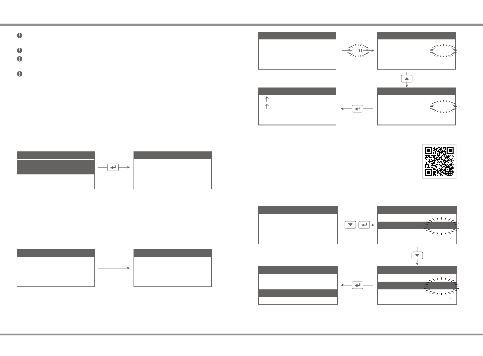
2.
First connect the 11~18V(60W or more) DC power adapter plug to the device, then plug the
110/220V AC power cable plug into the mains wall socket. In this order. The device boots up
and displays —after a prior Factory Reset— the UI Mode Selection.
U I M o d e S e l e c t i o n
1 ) D u m m y M o d e
( N i M H / L i I o n )
2 ) S i m p l e M o d e
3 ) A d v a n c e d M o d e
Select the UI Mode you feel more comfortable with. This page appears only once. You may
switch UI Mode under SETUP menu later if desired (see 5.).
Let's select Dummy Mode (This mode supports NiMH and LiIon only).
Insert round batteries in the empty slots observing correct polarity. In this particular UI Mode the
3.
battery type is detected automatically. Check if the displayed TYPE matches your battery
chemistry correctly. The SNB will be blinking alternately green and red to indicate that the slot
is ready. In Dummy Mode you can adjust charging current only, see next step.
Press ENTER to
confirm
# V O L T T Y P E C U R R
1
2
3
4
4.
N O B A T T E R Y
N O B A T T E R Y
N O B A T T E R Y
Insert batteries
N O B A T T E R Y
Press the blinking SNB. Its corresponding current value on the screen will be blinking to
indicate that the charging current can be adjusted now. Press ▲ and ▼ to alter the charging
current. Press ENTER button to start the charging process.
# V O L T T Y P E C U R R
1
2
3
4
N O B A T T E R Y
N O B A T T E R Y
N O B A T T E R Y
N O B A T T E R Y
# V O L T T Y P E C U R R
1
1 . 3 3 N I M H : 0 . 7 A
2
3 . 9 9 L I I O : 0 . 7 A
3
N O B A T T E R Y
4
N O B A T T E R Y
# V O L T T Y P E C U R R
1
1 . 3 3 N I M H : 0 . 7 A
2
3 . 9 9 L I I O : 0 . 7 A
3
N O B A T T E R Y
4
N O B A T T E R Y
Step 1
2
Press SNB
# V O L T C U R R m A h
1
1 . 4 5
2
4 . 0 8
3
N O B A T T E R Y
4
N O B A T T E R Y
When battery is fully charged the LED of SNB will turn green and you will hear beep tone.
0 . 7 0
2 . 9 0
3 5
1 4 5
Press ENTER to
start charging
# V O L T T Y P E C U R R
1
1 . 3 3 N I M H : 0 . 7 A
2
3 . 9 9 L I I O : 0 . 7 A
3
N O B A T T E R Y
4
N O B A T T E R Y
Press repeatedly to
increase current
# V O L T T Y P E C U R R
1
1 . 3 3 N I M H : 0 . 7 A
2
3 . 9 9 L I I O : 2 . 9 A
3
N O B A T T E R Y
4
N O B A T T E R Y
Step 2
Step 3Step 4
Video Tutorials
Please scan and watch the tutorial video above how to operate the charger
in dummy mode.
To change Dummy Mode to Simple or Advanced Mode click STOP to stop the operation of the
5.
charger first. Then press and hold the STOP button for one second to enter the SETUP menu.
Click ▼ down to UI Mode, then click ENTER. Click ▼ to select the new UI Mode.
S E T U P
L a n g u a g e :
U I M o d e :
N a m e s :
T e m p U n i t :
E n g l i s h
D u m m y
D e f a u l t
Step 1 Step 2
L a n g u a g e :
U I M o d e :
N a m e s :
C
T e m p U n i t :
S E T U P
L a n g u a g e :
U I M o d e :
N a m e s :
T e m p U n i t :
Press and hold ENTER to confirm and save your selection. You will hear a confirmation beep
tone and get transferred back to TOV.
E n g l i s h
S i m p l e
D e f a u l t
Press and hold to
confirm selection
C
L a n g u a g e :
U I M o d e :
N a m e s :
T e m p U n i t :
S E T U P
E n g l i s h
D u m m y
D e f a u l t
S E T U P
E n g l i s h
S i m p l e
D e f a u l t
Step 3Step 4
C
C
· 04
MC3000
MC3000
05 ·
Page 5
QUICK START GUIDE QUICK START GUIDE
Insert round batteries in the empty slots observing correct polarity. Be aware of the battery type!
6.
The display shows the voltage of the correctly inserted batteries and a blinking "PROGRAM[01]"
for them. "#1" refers to the first slot counted from the left, i.e. the slot with slot number button 1,
whereas "[01]" means the program with the program number 01. Note: In the Simple and
Advanced UI modes the device will NOT determine battery chemistry automatically but only issue
a warning at questionable battery voltage levels and for safety reasons refuse to proceed. For
incorrectly inserted batteries the screen continues to display "NO BATTERY" making you realize
that you did something wrong.
# V O L T C U R R m A h
1
1 . 3 3 P R O G R A M [ 0 1 ]
2
4 . 0 5 P R O G R A M [ 0 2 ]
3
4 . 0 1 P R O G R A M [ 0 3 ]
3 . 8 3 P R O G R A M [ 0 3 ]
4
Battery
Slot No.
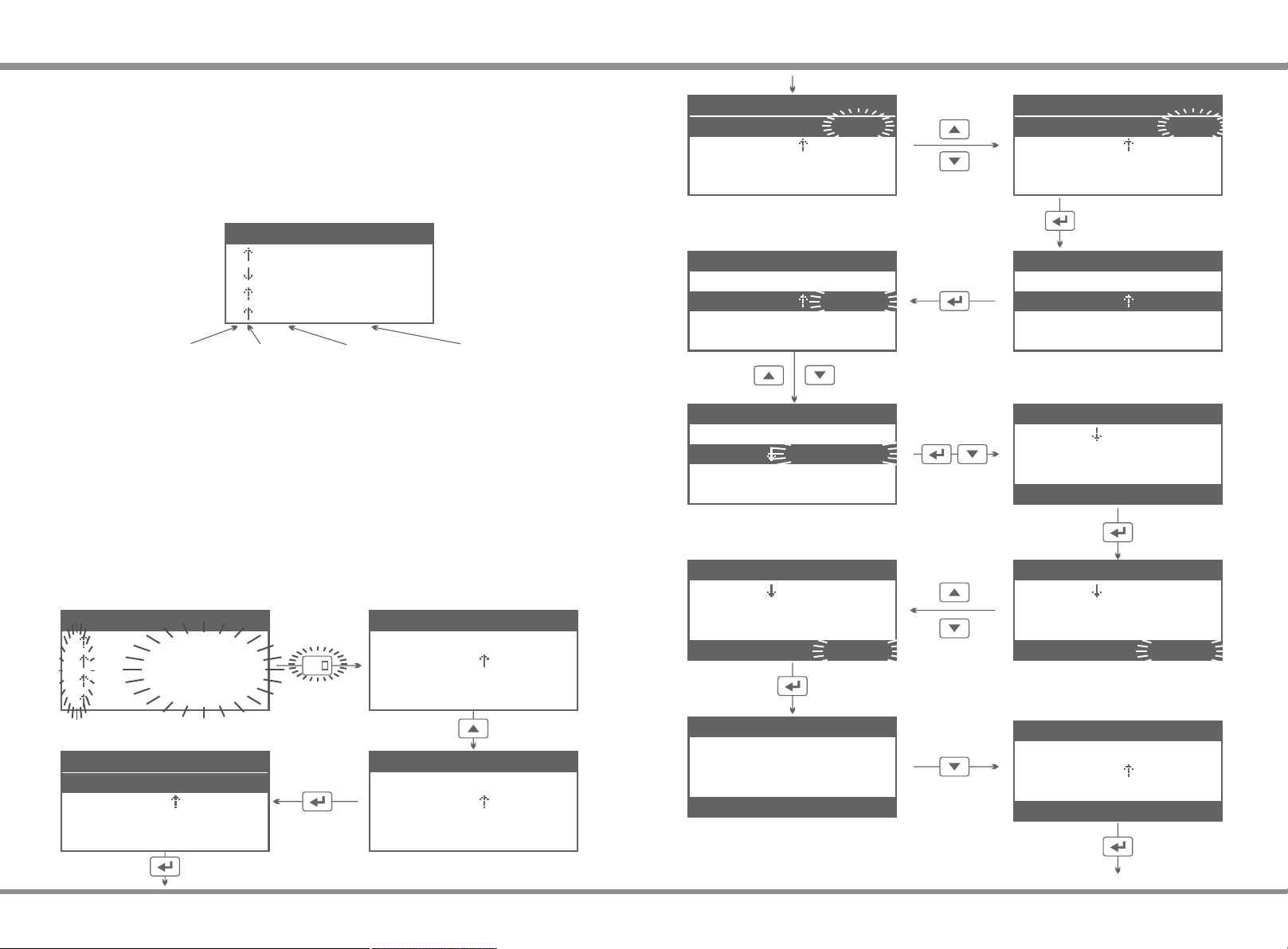
Before starting the slots, make sure that a proper program is assigned to them. For this, short-
7.
press the slot number buttons to transfer to Slot Programming View where you can change the
program number, or check & edit the respective program settings (see "How to Make a
Program"). Long-press the ENTER-button to confirm any changes made and to transfer back to
Total Overview.
Finally, long-press SNB of the ready slots to start their programs one after the other.
8.
Alternatively, short-press ENTER to start all the ready slots at once.
Operation
Mode
Battery
Voltage
ProgramNo.01-30
# 1 P R O G R A M [ 0 2 ]
B A T T T Y P E :
M O D E :
C A P A C I T Y :
C . C U R R E N T :
L i I o n
C h a r g e
O F F
1 . 0 0 A
# 1 P R O G R A M [ 0 2 ]
B A T T T Y P E :
M O D E :
C A P A C I T Y :
C . C U R R E N T :
N i M H
C h a r g e
O F F
1 . 0 0 A
Change to
Discharge
# 1 P R O G R A M [ 0 2 ]
B A T T T Y P E :
M O D E :
D i s c h a r g e
C A P A C I T Y :
C . C U R R E N T :
N i M H
O F F
1 . 0 0 A
Change
battery type
Access
operation mode
Confirm, then
Navigate down
# 1 P R O G R A M [ 0 2 ]
B A T T T Y P E :
M O D E :
C A P A C I T Y :
C . C U R R E N T :
Confirm selection
N i M H
C h a r g e
O F F
1 . 0 0 A
# 1 P R O G R A M [ 0 2 ]
B A T T T Y P E :
M O D E :
C A P A C I T Y :
C . C U R R E N T :
N i M H
C h a r g e
O F F
1 . 0 0 A
# 1 P R O G R A M [ 0 2 ]
M O D E :
C A P A C I T Y :
C . C U R R E N T :
D . C U R R E N T :
D i s c h a r g e
O F F
O F F
- 0 . 4 0 A
How to Make a Program
Example:
In slot #1, we insert NiMH battery. Let’s make program[02] for this battery (Discharge,
discharging current: 0.8A).
# V O L T C U R R m A h
1
1 . 4 8 P R O G R A M [ 0 1 ]
2
3 . 8 5 P R O G R A M [ 0 1 ]
3
3 . 8 6 P R O G R A M [ 0 1 ]
4
3 . 8 3 P R O G R A M [ 0 1 ]
# 1 P R O G R A M [ 0 2 ]
B A T T T Y P E :
M O D E :
C h a r g e
C A P A C I T Y :
C . C U R R E N T :
Access battery type
Continue on next page
· 06
L i I o n
O F F
1 . 0 0 A
1
Press SNB to
Go to SPV
Edit settings
of program[02]
# 1 P R O G R A M [ 0 1 ]
B A T T T Y P E :
M O D E :
C A P A C I T Y :
C . C U R R E N T :
Change to
program[02]
# 1 P R O G R A M [ 0 2 ]
B A T T T Y P E :
M O D E :
C A P A C I T Y :
C . C U R R E N T :
L i I o n
C h a r g e
O F F
1 . 0 0 A
L i I o n
C h a r g e
O F F
1 . 0 0 A
MC3000
# 1 P R O G R A M [ 0 2 ]
M O D E :
C A P A C I T Y :
C . C U R R E N T :
D . C U R R E N T :
D i s c h a r g e
O F F
O F F
- 0 . 8 0 A
# 1 P R O G R A M [ 0 2 ]
C A P A C I T Y :
C . C U R R E N T :
D . C U R R E N T :
O F F
O F F
- 0 . 8 0 A
C . R E S T I N G : O F F
MC3000
# 1 P R O G R A M [ 0 2 ]
M O D E :
C A P A C I T Y :
C . C U R R E N T :
D . C U R R E N T :
# 1 P R O G R A M [ 0 2 ]
C U T V O L T :
C U T T E M P :
Navigate down
C U T T I M E :
S A V E T O :
Save To (optional),
Press and hold to Save settings
Continue on next page
D i s c h a r g e
O F F
O F F
- 0 . 4 0 A
O F F
4 5 C
1 8 0 m i n
[ 0 2 ]
07 ·
Page 6

QUICK START GUIDE QUICK START GUIDE
The following illustration shows how the five common views of the user interface are
# V O L T C U R R m A h
1
1 . 4 8 P R O G R A M [ 0 2 ]
2
3 . 8 5 P R O G R A M [ 0 1 ]
3
3 . 8 6 P R O G R A M [ 0 1 ]
3 . 8 3 P R O G R A M [ 0 1 ]
4
Start All
I N F O M E S S A G E
# 1 :
# 2 :
# 3 :
# 4 :
S a v e d t o [ 0 2 ]
P R O G R A M [ 0 1 ]
P R O G R A M [ 0 1 ]
P R O G R A M [ 0 1 ]
interconnected:
SOV
Slot Operation View
SNB
DDV
Diagram Drawing View
# V O L T C U R R m A h
1
P r o c e s s i n g . . .
2
P r o c e s s i n g . . .
P r o c e s s i n g . . .
3
P r o c e s s i n g . . .
4
The parameters of other available program options can be changed in a similar manner. You
must always assign safe correct programs to the battery. There are 30 programs on the charger
which can be edited. Changes saved to the programs remain saved after a power cycle. Only
after a Factory Reset will your created programs get erased.
Programs
Starting
# V O L T C U R R m A h
1
2
3
4
1 . 4 5
3 . 8 5
3 . 8 6
3 . 8 3
- 0 . 8 0
1 . 0 0
1 . 0 0
1 . 0 0
3 2
4 0
4 0
4 0
Video Tutorials
Please scan and watch the tutorial video above how to make a program.
TOV
TOV/IMV
TOV/UCV
Total Overview
SNB
GSV
Global Setup View
The following table gives you a rough idea of the controls in the user interface:
Inactive Slot Active Slot
SNB#1
SNB#2
SNB#3
SNB#4
STOP
click: go to SPV of #1
depress: START #1
click: go to SPV of #2
depress: START #2
click: go to SPV of #3
depress: START #3
click: go to SPV of #4
depress: START #4
press in SPV/GSV: CANCEL, QUIT
depress in TOV: go to GSV
click: go to SOV/DDV of #1
depress: STOP #1
click: go to SOV/DDV of #2
depress: STOP #2
click: go to SOV/DDV of #3
depress: STOP #3
click: go to SOV/DDV of #4
depress: STOP #4
press in SOV/DDV: FINISH
press in TOV: STOP ALL
Slot Programming View
SPV
· 08
MC3000
UP
DOWN
ENTER
MC3000
press: scroll up thru SPV/GSV press: scroll up thru SOV/DDV
press: scroll down thru SPV/GSV press: scroll down thru SOV/DDV
click in SPV/GSV: ENTER, NEXT
depress: SAVE & EXIT
press in SOV/DDV: RETURN to TOV
press in TOV: START ALL
09 ·
Page 7

BATTERY KNOWLEDGE
BATTERY VOLTAGES
What Does 0.5C, 1C, -C/4, Etc Mean?
It is a short way of specifying charge transfer rates as function of battery capacity. Substitute the
nominal capacity for "C", divide by 1h, then multiply with the factor. For example, 0.3C for a
2100mAh battery equals a charge rate of 630mA or 0.63A (= 2100mAh/1h * 0.3 ), -C/4 or -0.25C
for a 3400mAh battery equals discharging it at 0.85A.
Choosing The Right Discharging Rate
The battery industry defines the so-called "standard discharge" as a controlled constant current -0.2C
discharge at room temperature; per definition, discharging a fully charged new battery under
these conditions will yield its nominal capacity. Furthermore, battery manufacturers often list
minimum or rated capacities at higher, more typical discharge rates such as -0.5C or -1C in the
specification sheets. Yet a more common practice for analyzing and comparing batteries from
different sources is to always assume the same fixed discharge current, -0.5A or -1.0A, i.e.
decoupled from the nominal capacity.
Choosing The Right Charging Rate
Rechargeable Li-batteries. Battery manufacturers define the so-called "standard charge" most
often as a 0.5C charge at room temperature. The user is advised to look up the confirmed details
in the battery specification sheet.
Rechargeable Ni-batteries. Charging too fast may damage the battery and not charge as fully,
whereas charging too slow requires longer time and may prevent the charger from terminating
correctly. Hence charging at a rate below 0.3C or above 1.0C is not recommended unless
otherwise indicated. In case of doubt, adhere to indications on the battery wrapper, look for the
spec sheet, visit candlepowerforums, or call the battery manufacturer and ask for the optimal
charging rate.
Battery manufacturers commonly specify recommended charge and discharge rates in datasheets
dependent on minimum, rated, typical, or nominal battery capacity. In practice it is easier to
compare the performance of different batteries by choosing a fixed pair of convenient rates, for
example either 1.0A/-0.5A or 1.0A/-1.0A, and reusing it for all batteries of similar or not so similar
size or capacity. With regard to battery voltages, in most cases it is not necessary to alter the
default values of the voltage options. In fact, it is dangerous to increase the maximum charge
voltage of Lithium-Ion batteries, and it is bad for battery health to discharge below the minimum
discharge voltage.
Nominal voltage
Charge voltage max.
(range)
Restart voltage
(range)
Storage voltage
(range)
Standard charge
Rapid charge
Standard |discharge|
NiMH / Eneloop
1.2V
1.65V
1.47~1.80V
OFF
1.30~1.45V
n/a
n/a
0.5C
≤1C
0.2C
NiCd
1.2V
1.65V
1.47~1.80V
OFF
1.30~1.45V
n/a
n/a
0.1~0.5C
≤1C
0.2C
NiZn
1.65V
1.90V
1.85~1.95V
OFF
1.50~1.88V
n/a
n/a
0.5C
≤1C
0.2C
RAM
1.5V
1.65V
1.40~1.70V
OFF
1.40~1.50V
n/a
n/a
0.5C
≤0.5C
0.2C
LiIon
3.6V 3.7V
4.20V
4.00~4.25V
OFF
3.98~4.18V
3.80V
3.65~4.00V
0.5C
≤1C
0.2C
LiIo4.35
3.8V
4.35V
4.10~4.40V
OFF
4.08~4.33V
3.90V
3.75~4.10V
0.5C
≤1C
0.2C
LiFePO4
3.2V
3.60V
3.40~3.65V
OFF
3.38~3.58V
3.30V
3.15~3.40V
1C
≤4C
0.5C
LTO
2.2V 2.4V
2.85V
2.60~2.90V
OFF
2.58~2.83V
2.40V
2.25~2.60V
1C
≤5C
0.5C
Battery Matching
As a general rule, do not mix batteries of different types, different capacities, different voltages, or
from different manufacturers in a multi-cell application. Use the Refresh mode to determine
capacities of the same battery product, then pair up or group matching cells within ±5% of the
measured capacity. Unmatched batteries in a multi-cell application can lead to reduced
performance or runtime, or ultimately to battery damage, over discharge or reverse polarity.
Battery Forming Charge
NiMH/NiCd batteries, new or stored for extended period, can become chemically deactivated.
Battery forming charge is a charge-discharge-charge cycle which forces a full charge into the
battery at a very slow rate. This process reactivates the battery. In certain cases, it needs to be
repeated two or three times. Battery forming charge can be emulated by using the Break_in mode
with the C>D>C sequence. For very best health and condition though, cycling two or three times
at standard charge/discharge rates may be more effective.
· 10
MC3000
Typical |discharge|
Disch voltage min.
(default)
(range)
MC3000
0.2~2C / 0.5~3C
0.95V
1.00V
0.50~1.10V
0.5~2C
0.85V
0.90V
0.50~1.10V
1~10C
1.00V
1.30V
0.50~1.50V
0.01~0.05C
0.80V
0.90V
0.50~1.30V
0.5~2C
2.50V
3.00V
2.50~3.65V
0.5~2C
2.75V
3.30V
2.65~3.75V
1~8C
2.00V
2.40V
2.00~3.15V
1~10C
1.50V
1.80V
1.50~2.25V
11 ·
Page 8

TOTAL OVERVIEW (TOV)
TOTAL OVERVIEW (TOV)
How to get there — Depending on the situation, depressing the STOP button or clicking it once,
twice, or thrice will get you back to TOV.
How to exit — In TOV, remove all batteries and unplug the device from mains.
# V O L T C U R R m A h
1
N O
B A T T E R Y
2
4 . 1 8
3
4 . 2 0
4
3 . 7 5
The total overview (TOV) is the main view where other views automatically revert to after periods
of user inactivity. In tabular format, it shows at a glance the most important bits of information
about the operation of the slots. The top line marks the column headers for slot number (#),
battery voltage (VOLT), current (CURR), and the transferred electric charge (mAh), often
lackadaisically called capacity. The 2nd row starts with “1”, for #1, and thus refers to the first slot,
i.e. the slot with the number 1 on its slot number button (SNB#1); the next row starts with “2”, etc.
The symbol next to the slot number indicates the operation mode. Voltage is displayed in units of
1 Volt (1V) rounded to 2 decimals, current is displayed in units of 1 Ampere (1A) also rounded to 2
decimals. Tracking the full resolution of 3 decimals (+0.001V, +0.001A) is possible through the PC
software interface only. Capacity is measured in units of 1 milliAmpere*hour (1mAh), higher
resolution (+0.1mAh) can be viewed on the PC through the PC Link.
When a battery is inserted – please mind correct polarity insertion – its voltage is displayed along
with the specific program preassigned to the slot and identifiable through its program number.
Unless you are sure that this is indeed the program you intend to run on your battery, you must
check or change the program number or the program settings.
TOV is also used for displaying message or quick info lines, for example at abnormal program
termination. In case of an error, the SNB would be blinking red and it is then up to the user’s
discretion to find out how to quit the error message. When certain viewssuch as SOV or SPV
return to TOV, the rows display for the duration of an instant helpful or not so helpful info snippets
regarding the respective program number.
The controls in TOV are as follows:
• When there are ready slots, pressing the ENTER button (=Start All) will start them at once. This
is useful if you do want to start all the ready slots together at the same time.
• If there are active slots, i.e. finished or busy, depressing the UP or DOWN button will get you to
DDV; otherwise it has no effect.
• When there are active slots, depressing the STOP button (=Stop All) will stop them simultaneously.
• If all slots are inactive, i.e. ready or empty, depressing the STOP button (=SETUP) will get you to GSV.
0 . 0 0 3 4 6 7
2 . 9 9 1 2 8 9
P R O G R A M [ 0 5 ]
• Clicking the SNB of an inactive slot will get you to its SPV.
• Clicking the SNB of an active slot will get you to its SOV, whereas depressing it will stop the slot.
The latter is useful if you want to fully stop the operation of particular single slot and not just finish
its program.
• Depressing the SNB of a ready slot will start the assigned program in the slot. This is useful if
you want to start the ready slots individually.
• Depressing the SNB of an "empty" slot will try to release the tripped protection circuit of
protected Li-Ion batteries. Repeat this procedure a few times until the seemingly empty slot has
turned into a ready slot.
• If there are ready slots, clicking UP+DOWN will process them for the reproducible
measurement of battery internal resistance. Also useful for checking and minimizing the contact
resistances within the electrical connection.
• If there are inactive slots, clicking UP+SNB or DOWN+SNB will recall the program number
stored under that shortcut and copy the program over to all inactive slots at once.
• In case of no batteries in the slots with no user activity for some time, an LCD screensaver will
get activated.
# V O L T C U R R m A h
1
1 . 2 6
2
1 . 4 9
3 . 0 7
3
3 . 8 5
4
By looking at the algebraic sign of the battery current and the symbols or their inversions it
becomes evident at which program stage the slots currently are. The symbols for the operation
modes are as follows. The inverted version appears in TOV after program completion:
Symbol for CHARGE operation mode: ↑
Symbol for DISCHARGE operation mode: ↓
Symbol for REFRESH operation mode: ↕
Symbol for CYCLE operation mode: ∂
Symbol for STORAGE operation mode: ∞
Symbol for BREAK_IN operation mode: ☼
Symbol for TRICKLE charge: T
Symbol for RESTING routine: ÷
- 1 . 5 0
0 . 0 3
0 . 0 0
- 0 . 0 4
4 3 2
2 3 7 8
3 1 0 9
6 5 4
· 12
MC3000
MC3000
13 ·
Page 9

GLOBAL SETUP VIEW (GSV) GLOBAL SETUP VIEW (GSV)
How to get there — In TOV, if all slots are inactive, depressing the STOP button will transfer to GSV.
How to exit — In GSV, pressing the STOP button once or twice will cancel changes, quit the view
and return to TOV.
S E T U P
L a n g u a g e :
U I M o d e :
N a m e s :
T e m p U n i t :
The MC3000 has numerous explicit options and their respective parameters which the user can
check or control. The more general settings are accessible in the global setup view (GSV). They
affect the operation of the entire device, not only of a single slot or program. Changes made to the
options are not saved until the view is quitted by depressing the ENTER button (=Save).
The controls in GSV are as follows:
• Pressing the UP or DOWN button navigates through the items, or lets the user make a selection.
• Clicking the ENTER button enters an option (=Enter), confirms a selection (=OK), or navigates
through all items from top to bottom (=Next).
• Depressing the ENTER button saves all changes and then transfers to TOV (=Save&Exit).
• Pressing the STOP button cancels changes (=Cancel) and ultimately may transfer to TOV,
thereby restoring the original SETUP (=Quit).
• In GSV, the SNB's are not responsive.
The items are in alphabetic order:
E n g l i s h
D u m m y
D e f a u l t
C
Bluetooth
Lets the user deactivate the Bluetooth 4.0 module for whatever reason. By default, Bluetooth is
activated.
Calibration Reset
Lets the user perform a reset of the device calibration back to production conditions. Clears userentered calibration data, typically 4 voltage measurements and 4 current measurements in total,
and restores the original calibration which was delivered ex factory. All user-entered calibration
data will be lost by overwriting. This reset is independent from the Factory Reset and affects
calibration data only.
Cooling Fan
Lets the user control the behaviour of the internal cooling fan. For example, "40°C" means that the
fan will remain off under 40°C SysTemp, then turn on at full speed to help the cooling and
eventually turn off at 35°C. "Auto" uses a super clever algorithm to calculate the optimal threshold
temperature at your personal environmental setup. When temperature continues to increase from
that start point on, rotational fan speed increases too.
Display
Lets the user control the behaviour of the LCD background lighting. For example, "1min" means
that the backlight will turn off after 1 minute of user inactivity, i.e. no pressing of buttons within that
period of time.
Dummy
Lets the user confirm NiMH/LiIon as the presently supported coupling of the two most common
rechargeable battery types in the Dummy UI Mode. Depending on market developments a selection of
further useful couplings of then other common battery types could be made available in future.
Dummy Charge
The factory default charging rate in the Dummy UI Mode is 700mA or 0.7A per slot, no matter the battery
chemistry nor battery size. In many typical situations this moderately low moderately high value represents
an agreeable point of departure and often does not need to be changed. Changing the Dummy default
charge rate could save the user the trouble of repeated button clicks in the long run.
Factory Reset
Lets the user clear memory and perform a soft reset back to original settings of the present firmware
version. In particular all changes made in programs and GSV will be lost. This reset is independent from
Calibration Reset and does not affect calibration data. Once a firmware update is applied, the original
ex-factory firmware version will be lost, so be prepared to adopt the newer firmware version for good.
FW Version
Shows the firmware version. A factory reset may be required to finalize the firmware update procedure
and show the updated firmware version.
Hide NiCd / Hide NiZn / ...
Lets the user hide less common battery types as possible parameters for the BATT TYPE option in SPV.
Hiding them allows for faster or safer selection of the more common battery types LiIon and NiMH when
programming slots. Less parameters for this critical SPV option may equate to less potential for
mistakes.
HW Version
Shows the version of the electronics hardware in an all-encompassing notation format, for example ≥1.3
means that the actual PCB revision number is 1.3, 1.4, 1.5, or higher.
Info Message
Lets the user set the time period for displaying information snippets in the info message view (IMV). IMV
contains differentiated information about the usage of program numbers in the four slots. TOV is
preceded by a short display of IMV when, for example, SOV or SPV gets transferred back to TOV.
Beginners may find it helpful to increase the time, the default is 2 seconds. Note that all interaction with
the device is blocked during that time.
I N F O M E S S A G E
# 1 :
P R O G R A M [ 0 1 ]
# 2 :
# 3 :
# 4 :
S a v e d t o [ 0 7 ]
C o p y o f [ 1 3 ]
U s i n g [ 2 9 ]
Input
Shows the momentary DC input voltage and lets the user set its lower bound of acceptability. If at higher loads
or unsteady mains the input voltage supplied by the power adapter drops too much, this setting would allow
operation beyond the device specification, i.e. below 11V minimum operating voltage.
Key Beep
Lets the user turn off the audible electronic feedback of button pressing or adjust its pitch for less
irritation. Very useful.
Language
Lets the user confirm English as the present system language setting of the user interface on the LCD
screen.
· 14
MC3000
MC3000
15 ·
Page 10

GLOBAL SETUP VIEW (GSV) SLOT PROGRAMMING VIEW (SPV)
LCD Contrast
Lets the user adjust the contrast of the LCD screen.
Names
This option controls the program naming format in TOV. By default and for simplicity, programs are listed
with their respective program numbers only. Some users might find it helpful for quick identification or
better overview to also see the underlying essential program parameters such as charge transfer rates
and battery chemistry.
Save To
Lets the user determine the default parameter of the option SAVE TO in SPV. See page 23 for more
information.
Screensaver
When all slots are left empty for a period of time, an LCD screensaver becomes active in TOV, until the
user operates the charger again by pressing buttons or inserting batteries. This option lets the user
control few aspects of the screensaver, for example OFF for complete deactivation.
UP + SNB#1 / … / DOWN + SNB#1 / …
Each slot number button can serve as shortcut to quickly restore most often used programs. Clicking, for
example, DOWN and SNB#3 at the same time in TOV would copy the program number, stored or
'memorized' here in GSV under this very key combo, over to all inactive slots at once. With the availability
of four SNB's you could recall a total of up to eight different favorite programs for this purpose.
Soft Charge
Lets the user control the voltage threshold of deep-discharged rechargeable Lithium batteries at which
the charge routine can proceed with the full user-set charging rate.
System Beep
Lets the user turn off the annoying beep tones at system events, e.g. when a slot has finished a
program.
SysTemp→ #1,#2 → #3,#4 → ...
Shows the temperature as recorded by 2 temperature sensors placed right at the internal aluminum cooler
and as reported by another 4 sensors at the slots. Note that these are correct values at the sensors
themselves and cannot be precisely the spatial temperature average of the targets of interest. Since it is
practically impossible to isolate thermal paths in a compact 4-bay charger, heat may reach the different
sensors from various directions and sources, hence actual battery temperature will be higher or lower than
indicated, depending on the complex charging and the environmental situation.
Temp Unit
Lets the user choose the preferred temperature unit to be displayed in GSV, SPV, SOV, and elsewhere.
UI Mode
Lets the user switch between a shorter (default) or an extended programming menu in SPV. The Simple
menu mode assumes reasonable fixed parameters for the options which are available in Advanced
mode yet hidden in Simple mode; their preset values can be inspected from within the Advanced menu
after a factory reset, for example identical 60min resting between charge and discharge routines.
Alternatively, a semi-automatic user interface can be activated which recognizes the given two battery
chemistries automatically and does nothing but a full Charge. NiMH covers full charging of NiMH, NiCd
and Eneloop; LiIon covers safe charging of LiIon and LiIo4.35. This UI mode may be convenient when
the user just wants to recharge common batteries and not bother much about the technical details of the
Charge operation mode. However, caution advised.
How to get there — In TOV, clicking the SNB of an inactive slot will transfer to SPV.
How to exit — Pressing the STOP button will eventually lead back to TOV without any changes
saved.
# 2 P R O G R A M [ 0 5 ]
B A T T T Y P E :
M O D E :
C A P A C I T Y :
C . C U R R E N T :
L i I o n
C h a r g e
4 2 0 0 m A h
3 . 0 0 A
Function
In slot programming view (SPV) the user can either change the program number to swiftly activate
any other of the 29 global programs, or edit the detailed settings of the chosen program. In total,
there are 30 programs on the charger which can be edited. Changes saved to the programs
remain saved after a power cycle. Only after a Factory Reset will your created programs get
erased.
Conception
After transferral from TOV first thing to be clear about is the program number in the slot, because
at any point in time a concrete program number is assigned to each slot and the user should
always be aware of which program, identifiable by its 2-digit number in square brackets, is set to
run in the slot under consideration. As the underlying concept behind the entire user interface,
there cannot be any slot with no program number assigned to it.
Saving
How or when are programs saved? Changes of program numbers are saved in situ, unless
cancelled by pressing the STOP button (=Quit). Changes of program settings are not saved until
the ENTER button has been depressed (=Save); the user is then automatically transferred back to
TOV (=Exit). Clearly, changes in the program settings are lost if not reconfirmed by depressing the
ENTER button!
Similar programs
A program which is currently in operation by an active slot could still be edited in an inactive
different slot and saved under the identical program number for modified operation in other slots.
This practice of template functionality is not recommended but may sometimes be useful for
making changes to an existing program without assigning new program numbers to similar
programs every time. Ongoing slot operation with the original program will not be affected by the
modified program settings until it is fully stopped and then restarted with the same program
number. In general, the recommended procedure for creating similar programs is to assign new
program numbers to them with the Save To program option.
· 16
MC3000
MC3000
17 ·
Page 11

SLOT PROGRAMMING VIEW (SPV)SLOT PROGRAMMING VIEW (SPV)
The controls in SPV are as follows:
• Pressing the UP or DOWN button navigates through the items, or lets the user make a selection.
• Clicking the ENTER button enters an option (=Enter), confirms a selection (=OK), or navigates
through all items from top to bottom (=Next).
• Depressing the ENTER button saves all changes and then transfers to TOV (=Save&Exit).
• Pressing the STOP button cancels changes (=Cancel) and ultimately may transfer to TOV
(=Quit), thereby restoring the original program settings or program number.
• Pressing the SNB of another inactive slot will keep the present program number saved to the
slot but cancel all changes made in the program settings, before switching to the SPV of the new
inactive slot.
• When selecting a program number for a ready slot, depressing its SNB saves the current
selection, transfers to TOV and then starts this very slot (=Save&Start).
• In SPV, the SNB's of active slots are not responsive.
The list of program options in SPV for all battery types combined is as follows:
BATT TYPE
In the present firmware the following battery types are supported:
• NiMH - Nickel-Metal Hydride battery, 1.2V nominal voltage. The most common type of consumer
class AA size rechargeable batteries for cameras, equipment, flashes, flashlights, tools, toys,
bedroom, etc.
• NiCd - Nickel-Cadmium battery, 1.2V nominal voltage. Has still its uses in today’s world of battery
packs but single cells have become a rarity as they are being phased out due to their environmental
toxicity. Stay away from children.
• NiZn - Nickel-Zinc battery, 1.65V nominal voltage. Charges to 1.9V, cannot take trickle charge,
should not be discharged lower than 1.3V. Low cost, high output cell, suitable for fast charging, can
be cycled 200–300 times. PowerGenix is a notable maker of NiZn batteries.
• RAM - Rechargeable or Reusable Alkaline battery, 1.5V nominal voltage. If not discharged deeper
than 50%, it could be cycled up to 25-50 times. Restricted depth of discharge, limited cycle count,
drastically lowered capacity on repeat charge, and the low load current didn't help its popularization.
RAM batteries can leak as nastily as Alkaline batteries.
• Eneloop - Not really a battery type but a brand name. Market leading professional grade NiMH-
based low self-discharge industrial standard superior battery product originally made in Japan by
Sanyo or FDK, now by Panasonic and also in China. The charging algorithm is the same as for
NiMH but some options in SPV have been adapted for more convenient presets. Can be cycled
2100 times according to claims in ads; visit eneloop.com or also eneloop101.com for further info.
• LiIon - standard Lithium-Ion battery, 3.6V 3.7V nominal voltage. Most common are Li-cobalt and Li-
manganese based chemistries, both can be charged safely with this setting. LiIon charging uses the
recommended CC-CV charging algorithm with user-definable termination current. Target voltage is
4.20V; setting it higher is dangerous, and protected 18650's would not let the charger charge higher
than that. In theory, a single non-cylindrical Li-Ion cell could be analyzed with the help of MC3000
plus some crocodile clip charging cables/aids, too, but for safety reasons the user is advised to
resort to dedicated hobby chargers in such cases.
• LiFe - Lithium Iron Phosphate battery, LiFePO4, 3.2V nominal voltage. A safer LiIon chemistry,
charges to 3.65V, must not be discharged lower than 2.0V. Not to be confused with Lithium
Polymer battery, LiPo.
• LiIo4.35 - Lithium-Ion High-Voltage battery, 3.8V nominal voltage. Very similar to standard
Lithium-Ion but these cells can be charged safely up to 4.35V. Samsung is the only known highquality manufacturer of such non-standard Li-Ion cells apart from LG. Since this menu item is
potentially hazardous to ignoramus, it becomes hidden after a factory reset. To be clear, you must
NOT use this battery type setting with standard Li-Ion batteries!
• LTO - Lithium-Titanate battery, 2.4V nominal voltage. One of the safest Li-ion chemistries
around, because of low capacity typically in form of battery packs for UPS, electric powertrains,
solar-powered street lighting, or similar professional applications, offers very long life span of
thousands of cycles at high charge/discharge rates and also superior performance at cold
temperatures. Single cells, cylindrical or not, remain a rarity on the market.
MODE
There are up to 6 typical charging programs, or operation modes, to be found in hobby chargers
and advanced battery chargers. MC3000 has them all, and additional ones could be provided in
future firmware upgrades.
• Charge - Charges your battery. Uses the proper algorithm for the chosen battery type, constant
current (CC) for NiMH, CC for Eneloop, CC-CV for NiZn, CC-CV for LiIon, etc. Charging
terminates when the battery is full or some other termination criteria have been met. Useful when
battery needs to be recharged without determining the capacity of the battery. Should be used on
batteries known to be in good condition and which have been in continuous use. Requires the
least amount of time.
• Refresh - Practically the same as Cycle operation mode with setting C>D>C and N=1, first
charges, then fully discharges, followed by a full recharge, with rests in between. Reports
discharge and charge capacitiesinSOVafter the end of the cycle. Useful for automatically
analyzing battery capacity while ending up with fully charged batteries. Also useful for
rechargeable Ni-batteries with degraded performance, recommended once every ten cycles for
NiMH batteries. Note that this or similar operation mode has confusing names in other battery
chargers, Refresh&Analyze Mode, Test Mode, Nor Test Mode, Check Mode, Cycle Mode, Alive
Mode, etc. MC3000 doesn't call it names, just look at its fixed program definition in SPV.
• Break_in - Based on norm §7 of IEC 61951-1 Ed. 3.0 2013-10 and IEC 61951-2 Ed. 3.0 2011-
05, this mode enables the user to perform the industrial standard procedure to verify the declared
rated capacity of single NiCd or NiMH cells. The norm specifies that first the battery shall be
discharged at -0.2C constant current down to 1.0V cut-off, then charged at 0.1C CC for exactly
16h including a 6h overcharge, afterwards stored for 1-4h, and finally discharged for at least 5h at
-0.2C CC down to 1.0V cut-off again. This 28h+ long D>C>D procedure shall be repeated up to 5
times until the rated capacity has been met, otherwise the battery rating is no good. Similarly, the
39h+ long C>D>C procedure can serve as battery forming charge, once every 30 cycles for NiMH
batteries or every half year, recommended both for brand-new batteries and for batteries that
cannot be rescued by the Refresh mode. Because of the timer based charge termination Break_in
cannot be simulated by the Cycle operation mode. Not available for NiZn nor for rechargeable Libatteries.
· 18
MC3000
MC3000
19 ·
Page 12

SLOT PROGRAMMING VIEW (SPV)SLOT PROGRAMMING VIEW (SPV)
• Discharge - Primitive operation mode which does nothing but 1 discharge routine, D, eventually
followed by a rest phase, i.e. D>. Maximum discharge current is -2.00A per slot for all battery
types, restrictions apply. Useful for analyzing the remaining amount of electric charge stored in the
battery.
• Cycle - Automatically repeats the three distinct routines after the specified pattern. Useful for
unattended operation over an extended period of time or testing the degradation of China made
Eneloop after 100 cycles. Cycling a few times at high rates may help to condition new NiMH cells
or awake old batteries from slumber; interrupt the cycling when the discharge capacity has
seemingly reached a plateau. Note that a battery can be re-cycled only so many times before its
end-of-life.
• Storage - Available for rechargeable Li-batteries, generates recommended stable voltage levels
in preparation for long-term storage. Uses the technique of reduced charging (CV-phase) and
reduced discharging (inverse CV-phase) to approach the target voltage. For storing rechargeable
Ni-batteries, no such preparation is needed, see BU-702.
CAPACITY (or NOMINAL)
Primarily meant as safety option, lets the user set a reasonable upper limit for the transfer of
electric charge per discharge or charge routine of a program. Enter, for example, 4200mAh for a
20% buffer on a 3500mAh rated battery. The capacity cut-off is to prevent overcharging or
overdischarging, especially of batteries with unknown performance or capacity. Or, may be set to
stop the slot prematurely on purpose after the transfer of a well-defined amount of electric charge.
In some situations it may be convenient to just set it to OFF. In Break_in mode, this option is
labeled NOMINAL and the user is required to enter a value as exactly as possible, the nominal
capacity of the battery.
C.CURRENT
The nominal charge current. Must be set for operation modes which include at least 1 charging
routine. In Simple menu mode the charge current is set in +0.1A steps from 0.1A to 3.0A; in
Advanced menu mode it is set in +0.01A increments from 0.05A to 3.00A. It is OFF for Discharge,
and preset for Break_in operation modes. MC3000 uses constant current for charging, not pulsed
charging. Note that the initial charging current automatically decreases during the CV-phase of
LiIon charging or storage mode. For programs with even lower CC charging currents than 0.05A,
you could try to be clever with the TRICKLE C. option.
D.CURRENT
The nominal discharge current. Must be set for operation modes which include at least 1
discharging routine. In Simple menu mode the discharge current is set in +0.1A steps from -0.1A
to -2.0A; in Advanced menu mode it is set in +0.01A increments from -0.05A to -2.00A. The device
can discharge 4× Ni-based batteries at -2A/slot or 4× Li-based batteries at -1A/slot at a time.
However, the device can discharge only 1× Li-based battery at -1.01…-2.00A at a time; when
another slot is started, all busy slots would be cut in their discharge power in parallel. So in order
to guarantee 1× LiIon battery at -1.01…-2.00A undiminished discharging current, no other slot can
be busy. MC3000 uses constant current for discharging, not pulsed discharging. Note that the
initial discharging current automatically decreases when the D.REDUCE option becomes active.
For programs with even lower discharging currents than -0.05A, you could help yourself and play
with the D.REDUCE option.
C.RESTING
Defines the duration of the resting phase subsequent to the charging routine. Can be set to
anything between 0 and 240 minutes for operation modes which include at least 1 charging
routine. During this period the current is 0.00A, or trickling if TRICKLE C. was set, and the battery
can cool down and rest. It is OFF for Discharge operation mode, and there is no resting phase
after a cycling operation mode has finished.
D.RESTING
Defines the duration of the resting phase subsequent to the discharging routine. Can be set to
anything between 0 and 240 minutes for operation modes which include at least 1 discharging
routine. During this period the current is 0.00A, and the battery can cool down and rest. It is OFF
for Charge operation mode, and there is no resting phase after a cycling operation mode has
finished.
CYCLE COUNT
Number of cycles. Option relevant only to cycling operation modes such as Cycle (N=1…99) or
Refresh (N=1). It is OFF for all other operation modes including Break_in. As in sports a trade-off,
cycling repeatedly is good for present health, condition and performance on the one hand, on the
other hand it ages substance faster and shortens lifespan. Ambitious battery testers can learn
about the decline of capacity after numerous cycles.
CYCLE MODE
For our purpose, a so-called cycle be defined as sequence of at least 1 charging and 1
discharging routine, or vice versa. "D>C>D", for example, will start with an initial discharge before
performing a complete charge followed by a complete discharge. For N>1 the program repeats
the pattern such that a complete charging routine always alternates with a complete discharging
routine, or vice versa. "C>D>C, N=2" would result in (C)>D>C>D>C, "C>D, N=2" in (C)>D>C>D.
While the user can specify C.RESTING and D.RESTING to be applied between the charge
transfer routines, the Cycle program signals the finishing of the program directly after the final
charge transfer routine.
TARGET VOLT
Similar to CUT VOLT, it states the direction and target, i.e. the voltage where the charging routine
is heading towards to terminate the routine. Often termed 'end voltage', the exact technical
meaning of this value differs slightly depending on battery chemistry or operation mode: the
charging of a NiMH/NiCd battery ends as soon as the off-load voltage has reached this point, or it
is the on-load constant voltage during the CV-phase of rechargeable Li- or NiZn-battery charging,
or it is the storage voltage in the Storage mode of rechargeable Li-batteries. Unless you’re sure
why you’re doing what, better stay on the safe side and do not deviate from the default values.
CUT VOLT
The discharge cut-off voltage. Applies to discharging routines of operation modes other than
Storage. It is the voltage, measured under load, at which the routine will terminate the
discharging; or, when D.REDUCE is active, it is the constant voltage during the inverse CV-phase
until the routine terminates the discharging. Before the start of the discharge, this value should be
lower than the battery voltage to make any sense. If set too low, the overdischarging will damage
the battery.
· 20
MC3000
MC3000
21 ·
Page 13

SLOT PROGRAMMING VIEW (SPV)SLOT PROGRAMMING VIEW (SPV)
CUT TEMP
The temperature cut-off. It is the temperature of the battery, or more precisely the temperature at
the slot sensor, at which the program will stop with an abnormal program termination message. A
safety option, it can protect batteries against unexpected overheating. While recommended for
better air circulation around the round battery, measurement of battery temperature will be
particularly off when the battery is left hanging suspended between the contacts.
CUT TIME
The timer cut-off. Stops the program with an abnormal program termination message when the
total time has reached this value. Primarily devised as safety option, it could also be used for
intentional program stops after a given time of operation, for example in conjunction with the Zero
or -Zero parameters of the Storage operation mode.
TERMINATION
The termination current of the CV-phase of Li-Ion battery charging algorithm, also of NiZn. When
reaching TARGET VOLT, e.g. 4.20V, this option will hold the voltage constant while automatically
reducing the current down to the specified value before it terminates the charging routine. A high
termination current serves battery health but will not charge the full battery capacity. The
parameter defaults to 10% of C.CURRENT, an industrial standard. "Zero" means an ever
decreasing charging current: not good for your patience or battery but allows to produce quasiconstant 4.200V battery voltage if that’s what you’re after. OFF means no CV-phase once the
target voltage has been reached.
D.REDUCE
Discharge Reduce. Applies to the discharge routine of a program. Inversely similar to the CVphase of Li-Ion battery charging algorithm, when reaching CUT VOLT, this option will hold that
voltage constant while automatically reducing the current down to the specified value before it
terminates the discharging routine. Setting this option will extend the discharging period beyond
the time for normal discharge cut-off, discharge even more electric charge, but never let the
battery fall below the cut-off voltage. Since battery offline voltage tends to recover after a
discharge process, reducing the discharge current helps to reduce the extent of recovery. "-Zero"
means that the discharge current will continue to decrease, approaching 0A infinitesimally;
beware, this could take forever and may also not serve battery health. Not terribly useful in most
cases, the Storage operation mode does profit from this option though.If you are confused, just
turn it OFF.
RESTART VOLT
The restart voltage. Applies to programs which end with a charging routine. When such a program
has finished, the voltage of bad-health batteries is prone to decline rather fast due to selfdischarging phenomena. Setting this value for example 0.05V lower than TARGET VOLT will
guarantee a minimum battery voltage when removing the battery. Naturally, one cannot set it
higher than the TARGET VOLT parameter. What exactly will happen when the voltage has
dropped by the 0.05V? That depends on the firmware version. Generally speaking, the slot
restarts some charging. For all operation modes the factory default is OFF.
DELTA PEAK
Delta-peak sensibility. A technical parameter to control charge termination of NiMH/NiCd batteries
through the commonly recommended negative delta voltage -dV or -dV/dt method, or through the
zero delta voltage method, 0dV or 0dV/dt. When charging a healthy specimen at constant current
the voltage graph normally peaks around full charge completion. A higher setting will ensure that
this peak has been passed with certainty but will also charge longer than necessary. "0dV" will
terminate the charging when the peak extends to a voltage plateau, i.e. does not show a well
defined voltage drop. The latter may happen with old batteries or at very low charge rates or both.
As a rule of thumb, use -dV for topped off charging and 0dV as no-brainer in all other cases.
TRICKLE C.
Trickle charge. A small current typically applied after a Charge or Refresh program has finished to
counter the effects of self-discharge, it helps to keep the batteries topped off, i.e. fully charged, as
long as the batteries are left in the charger tray. Not contributing to the capacity nor the energy
count, available for NiMH/NiCd batteries only, and with modern LSD batteries often neither
needed nor wanted, a too high value may overcharge and keep the battery heated, which would
not serve battery health. Use with good reason. The factory default is OFF.
TRICKLE TIME
Determines the point in time when the trickle charge should be applied. When a program finishes
with a charging routine, End would cause trickling to set in right after that last charging routine and
continue indefinitely, until the user stops the slot. Rest would cause trickling to be applied during
all C.RESTING phases of the program for the exact duration of the rest phase: in a Cycle program
between the Charge>Discharge routines, or when a program finishes with a charging routine plus
a subsequent rest phase.
SAVE TO
After a Factory Reset, this SPV option defaults to the present program number in the slot under
consideration, referred to as "Slot" in the GSV option of the same name. Changing the program
number here allows the user to save the entire modified set of program settings under a different
program number, leaving the original set of program settings intact, very similarly to the "Save
As..." function as known from common PC software applications. The parameters "Ready" and
"All Slots" facilitate assigning identical programs, duplicates, to other slots by overwriting in
parallel the currently assigned programs. "Ready" saves the program under the present program
number to all ready slots. "All Slots" first saves the changes under the present program number
and then copies the entire program including its program number over to all four slots; in currently
active slots, the new program will not become active until the slot with the ongoing program has
been stopped.
Example: In TOV, slot#1 be empty and assigned with PROGRAM[09]. In SPV, after decrementing
the program number of/in #1 from [09] to [03] at the inverted top row, you access PROGRAM[03]
to edit its settings, thereby generating a "[03*]" in #1 so to speak. The last row in SPV defaults to
SAVE TO [03]; depressing <ENTER> would just save [03*] under [03] and make it the active
program in #1. Depressing <ENTER> on SAVE TO [05] would save [03*] as program[05],
overwriting whatever PROGRAM[05] has been before, and return to TOV; the original [03] stays
intact in #1, as if untouched. If (inactive) slot#2 was assigned with [05] before, then #2 would be
now ready yet to run the [03*] so to speak. Depressing <ENTER> on SAVE TO All Slots would
first save [03*] under [03] and then make it the new program in all slots. Depressing <ENTER> on
SAVE TO Ready would first save [03*] under [03] and then scan for ready slots: if there were any
ready slots, [03] would become their new program; however, since #1 is an empty slot in our
example, the slot would keep [09] and not adopt [03].
· 22
MC3000
MC3000
23 ·
Page 14

SLOT OPERATION VIEW (SOV) SLOT OPERATION VIEW (SOV)
How to get there — In TOV, when there is at least one active slot, clicking its SNB will transfer to
SOV.
How to exit — In SOV, pressing the ENTER button will return back to TOV. Or, after some period
of user inactivity, returns to TOV automatically.
# 2 L i I o n
M o d e :
C a p a c i t y :
V o l t :
C . C u r r e n t :
Naturally the slot operation view (SOV) is available for active slots only, i.e. slots with an ongoing
program (SNB: solid red) or slots with a finished program (SNB: solid green). For such slots, SOV
can be accessed through TOV. Apart from the most basic info already given in TOV, it also shows
quantities such as power, energy, time, temperature, internal resistance, and target voltage.
Whenever SOV is transferred back to TOV, the program numbers of the slots are being displayed
for a short period in the info message view (IMV).
C h a r g e
9 m A h
3 . 9 7 / 4 . 2 0 V
2 . 9 9 A
The controls in SOV are as follows:
Pressing the UP or DOWN buttons will scroll through the info lines.
In SOV, SNB's of inactive slots are not responsive.
For active slots, clicking the SNB will switch to its SOV, whereas depressing the SNB will fully
stop the slot. The latter will make the SNB turn from solid red or solid green to blinking redgreen.
Similarly to DDV, for busy slots, depressing the STOP button (=Finish) will stop the ongoing
routine and finish the entire program at this point, prematurely. The SNB turns from solid red
to solid green. This function provides some manual interactivity and control, if ever needed.
Pressing the ENTER button (=Return) will return back to TOV.
The top line shows the slot number to the left and the battery type to the right. The items are in
order:
Mode
Shows which kind of operation mode is running, or has finished, in the slot. For example, the
NiMH battery type has 5 possible operation modes: Charge, Refresh, Cycle, Break_in, Discharge.
For fast identification each operation mode is accompanied by a corresponding symbol.
Capacity
Shows the absolute value of the accumulated electric charge as it is being transferred between
device and battery: discharging capacity during discharge routines, charging capacity during
charge routines. At the end of cycling programs such as Break_in, Refresh, or Cycle, the results
of their discharging routines are shown too. The original physical unit is Coulomb, or more
typically, milliAmpere*hour (1mAh).
Volt
Shows both the actual battery voltage and the end voltage, i.e. the voltage where the charging or
discharging routine is heading towards to terminate the routine. In SPV, for discharging routines
the end voltage is called the cut-off voltage (CUT VOLT), for charging routines it is called the
target voltage (TARGET VOLT), and for the storage operation mode it is called the storage
voltage (TARGET VOLT, too). The physical unit is Volt (1V). While both values are displayed with
2 decimals, internally the device measures with +1mV resolution and accuracy.
Average
Shows the average voltage of the present charge or discharge routine. During the routine it is
being calculated as the mathematical time integral of the actual battery voltage from the beginning
of the routine, divided by the routine time up to this point in time, and it is hence a theoretical
construct. In a direct fair comparison of battery quality, usually batteries with higher average
voltage are preferable. The concept of nominal battery voltage can be traced back to this
calculational construct.
D.Current (or C.Current)
Shows the actual current flowing through the battery as it is being measured by a precision subOhm current sense shunt in real time. Negative values represent discharge currents, positive
values charge currents, according to EE101. The physical unit is Ampere (1A). While the value is
displayed with 2 decimals, internally the device measures with +1mA resolution and accuracy.
Power
Shows the momentary time rate at which electric energy is being transferred between device and
battery. Mathematically, electric power of the battery is simply the product of momentary battery
voltage under load and momentary battery current. Following the passive sign convention,
negative values represent a battery being discharged, positive values a battery being charged.
The physical unit is Watt (1W). Roughly speaking, the max charge power is about 13W/slot, the
max sustainable continuous discharge power is about -13W/device.
Energy
Shows the amount of electric energy which has been transferred between device and battery
since the start of the ongoing charging or discharging routine. A positive value means energy
transfer from device to battery (charging), a negative value means energy transfer from battery to
device (discharging). Not all energy transferred from device to battery is stored in the battery;
some part of it gets lost in the immediate environment in form of dissipated heat, mostly due to the
internal resistance of the battery. The physical unit is Joule, or more typically, Watt*hour (1Wh).
Time
Routine time. Shows the elapsed time since the start of the present routine. A program can
consist of several routines. When a new routine within a program starts, this timer is reset to zero.
· 24
MC3000
MC3000
25 ·
Page 15

SLOT OPERATION VIEW (SOV) DIAGRAM DRAWING VIEW (DDV)
Total
Total time. Shows the elapsed time since the start of the program. In SPV, for long-term cycling
make sure to set the parameter of the CUT TIME program option to OFF because CUT TIME is
limited to 1 day, whereas the timer of Total can count up to days and days.
BattTemp
Shows the battery temperature, or to be more precise, the slot temperature. Same value as seen
in GSV, it mostly serves as safety feature for battery overheat protection. To change the
temperature unit, go to GSV and change Temp Unit. Note that physically, temperature is a scalar
field quantity, i.e. any point on the battery surface will have a different temperature and depending
on the charging situation and your environment, the extreme temperature points on your battery
may be notably cooler or warmer than the single value given here.
SysTemp
Shows the internal system temperature. Same value as seen in GSV, it serves as safety feature
for device overheat protection. At full load it can go as high as 80°C or higher and will shut down
operation thereabout. The cooling fan is controlled by this value.
Batt IR
Shows the internal battery resistance in milliOhm (1mΩ). At the start of a program, the device
always performs a quick standard test first in order to determine the internal battery resistance.
Aged or poor condition batteries have a higher IR and therefore heat up more during charge or
discharge. This measurement might be slightly less accurate and reproducible than the separate
Batt IR measurement in TOV. In both cases battery contacting pressure and battery temperature
may affect it.
How to get there — In TOV, if there is at least one active slot, clicking the UP or DOWN button will
transfer to DDV.
How to exit — In DDV, pressing the ENTER button will return back to TOV. Or, after some period
of user inactivity, returns to TOV automatically.
# 1 3 . 9 8 V 0 0 0 : 0 1 : 0 0
The diagram drawing view (DDV) is a convenient way to get a quick overview of the battery
voltages, the internal temperature of the charger, or other relevant system quantities, graphed
over time. For the voltage graphs, the scaling of both axes is changed dynamically in order to
present the data in a meaningful way. For the charger temperature SysTemp, the vertical axis is
fixed. Since the horizontal axis represents the total time, very long program durations, for example
a CYCLE program with tens of cycles, will make the diagram look funny, so for higher resolution of
data and graphs the user is advised to do some PC time with the PC Link software. The displayed
voltage is live and in real time during the operation of a program (SNB: solid red), and its
recording stops after the program has finished normally (SNB: solid green). DDV can be accessed
from TOV only and there should be at least one busy or finished slot.
The controls in DDV are as follows:
Pressing the UP or DOWN buttons will cycle through the graphs of active slots.
In DDV, SNB`s of inactive slots are not responsive.
For active slots, clicking the SNB will directly switch to its graph, whereas depressing the SNB
will fully stop the slot. The latter will make the SNB turn from solid red or solid green to blinking
red-green.
Similarly to SOV, for busy slots, depressing the STOP button (=Finish) will stop the ongoing
routine and finish the entire program at this point, prematurely. The SNB turns from solid red to
solid green. This function provides some manual interactivity and control, if ever needed.
Pressing the ENTER button (=Return) will return back to TOV.
· 26
MC3000
MC3000
27 ·
Page 16

USER CALIBRATION
USER CALIBRATION
Very similar to the technology of a modern digital multimeter, the microprocessor of MC3000
measures the actual battery current (in series) and the actual battery voltage (in parallel) directly
at the battery in order to control and regulate the discharge or charge process. During the
manufacturing process every MC3000 production unit gets tested and calibrated to 2 decimals in
an expeditious process observing highest factory standards. Ambitious users who trust their own
expensive equipment more, prefer their personal fluke to serve as reference, or look for the grain
of supreme precision have the possibility to adjust the MC3000 factory calibration by a few
counts. Note that production calibration procedure, undocumented in this user manual, differs
from the following documented calibration procedure in user calibration view (UCV).
Steps for user calibration (Voltage):
# V O L T C U R R m A h
1 C a l i b . V : 4 . 1 0 3 V
3 . 9 6
4 . 1 5
4 . 0 8
Have a set of 4 batteries with stable offline voltage, preferably all over 4.0V, at hand. With your
1.
digital multimeter, measure their voltages accurately with a resolution of 3+ decimals in the
"1V"-range setting, e.g. "4.10285V, 3.97013V, etc".
Have the MC3000 connected to power and display TOV. Insert all 4 batteries. Depress SNB#1
2.
and the STOP button simultaneously until the battery voltage in slot#1 is being displayed with 3
decimals, e.g. "4.098V", and release the 2 buttons in time. You are now in voltage calibration
mode for slot#1.
Enter your own DMM measurement rounded to 3 decimals, in this example 5 counts up to
3.
"4.103V" (4.10285 = ~4.103), with the help of the UP or DOWN button and save by depressing
the ENTER button. Saving takes a few seconds.
Repeat the procedure similarly for the remaining 3 slots: depress SNB#2 and STOP
4.
simultaneously until the battery voltage in slot#2 is being displayed with 3 decimals and
release, etc.
Recheck if the voltage readings of MC3000 and offline with your personal fluke do coincide for
5.
other batteries with stable voltages.
Note: One does not need 4 different batteries for voltage calibration. As long as the battery has
stable voltage, the same battery can be reused in all 4 slots. Similarly, one does not need 4
different batteries for current calibration. As long as the battery is able to supply high constant
current over the duration of the calibration process, the same battery could be reused in all 4
slots.
Steps for user calibration (Current):
# V O L T C U R R m A h
1
C a l i b . C :
2
3 . 9 0 - 1 . 0 0
3
4 . 1 1 - 1 . 0 0
4
4 . 0 6 - 1 . 0 0
Have a set of 4 fully charged high performance batteries at hand. With your digital multimeter,
1.
get prepared to measure the battery current online in series accurately with a resolution of 3+
decimals in the "1A"-range setting.
Have the MC3000 connected to power and display TOV. Insert all 4 batteries. Run a constant
2.
current discharge program at -1.00A in slot#1. Wait until the multimeter shows a stable
reading, e.g. "-1.00639A", then depress SNB#1 and the STOP button simultaneously until
the battery current in slot#1 is being displayed with 3 decimals, e.g."-1.000A", and release the
2 buttons in time. You are now in current calibration mode for slot#1.
3.
Enter your own DMM measurement rounded to 3 decimals, in this example 6 counts up to
"-1.006A" (1.00639 = ~1.006), with the help of the UP or DOWN button and save by
depressing the ENTER button. Saving takes a few seconds. Observe how the multimeter
reading automatically begins to drift from "-1.00639A" to a perfect "-1.000.. A" booyah.
4.
Repeat the procedure similarly for the remaining 3 slots: run the same -1.00A discharge
program in slot#2, wait until the multimeter shows a stable reading, then depress SNB#2 and
STOP simultaneously until the battery current in slot#2 is being displayed with 3 decimals and
release etc. Note: If in one slot the new reading fluctuates lively at the 3rd decimal, e.g.
between "-0.999.. A" and "-1.000.. A", then depress SNB+STOP again and, in this example,
enter "-0.999A"; the resulting overshoot might fluctuate now between "-1.002.. A" and "-
1.001.. A", then enter "-1.002A" and so on. This recursive procedure can appear tedious and
hopeless but eventually will lead to the desired "-1.000.. A" multimeter reading without
noteworthy fluctuations: you have reached the perfect calibration point for that one slot, too!
Recheck if the current readings of MC3000 and online with your personal fluke do coincide for
5.
other programmed discharge rates, e.g. -0.05A, -0.10A, -0.50A, -1.50A, -2.00A.
In theory you could also use a lower voltage battery for voltage calibration or a lower discharge
current for current calibration, however for guaranteed consistency across the 4 slots and the
entire voltage and current ranges we do not recommend lower values than the above suggested
ones, 4V and 1A. Since temperature of components and environment alters measurements by
precision electronics, please make sure that user calibration is done under isothermal conditions
to make any sense. In case of error or mistake, you can reset the calibration to ex factory
conditions with the Calibration Reset menu item in GSV. Good luck.
- 1 . 0 0 6 A
2 7
1 6
9
· 28
MC3000
MC3000
29 ·
Page 17

PC LINK
FIRMWARE UPDATE
The visualization of data helps with the understanding of battery performance or the details of
charging algorithms. The free PC Link software offers convenient operation and overview of the
charger from a Windows computer; it may also be needed for downloading and installing the
latest firmware updates. The software automatically retrieves the program settings of each slot,
and with the click of a mouse the user can simultaneously monitor the most important quantities of
the four slots through real-time graphs and, for example, track all charge and discharge capacities
of an extensive cycle program. For more detailed analysis or post-processing the user could
export the data to *.CSV-spreadsheet format and import the file to M$ Excel or other third-party
software applications.
In order to connect the charger to the computer and use the PC Link software, the user is required
to use a USB cable which is not included in this package. The cable should be a high-quality
premium USB data cable (Anker, Remax, BlitzWolf, a.o.) to ensure data integrity, and must be
terminated on one end with USB type A plug for the connection to the PC and the opposite end
with Micro-USB type B plug which connects directly to the charger at the PC Link port.
As with any other smart piece of software, handling the program itself is intuitive and selfexplanatory; no help file or usage documentation is available. For information on technical options
and parameters of the device, please refer to the corresponding sections in this device manual.
In the present PC software version it is not possible to combine several programs, e.g. -2A
discharge to 3.6V followed by -1A discharge to 2.8V, to a single composite program. In the
meantime the user could program different charge steps in separate program numbers and carry
out the combination of steps manually.
The latest version of the SkyRC PC Link software for Windows PC can be downloaded from
www.skyrc.com. Free third-party MC3000 compatible PC Link software for Win/Mac/Linux could
be found on lmgtfy.com.
It is not necessary to update the firmware of a device because in most cases the user is good to
go with the firmware version delivered ex factory. However firmware updates are an opportunity
for the company to make small changes, expand the code and let the user profit from continued
development without extra cost. User submitted suggestions for incremental changes in the
firmware will be gathered, evaluated and decided upon on a regular basis. In principle various
methods for the transfer of the update to the device would be technically possible, for example an
updating procedure involving the PC Link software as follows:
Remove all batteries, disconnect all USB cables and power cables, deactivate Bluetooth
1.
everywhere, close and exit all software and hardware on your Windows PC which access the
USB communication. Connect the device to its power supply.
2.
Use the PC Link premium USB data cable to connect the device to your Windows PC. In
many cases no further device drivers or USB drivers need to be installed. Launch the official
PC Link software and test the functionality of the software.
In the PC Link software click on Firmware Update and wait patiently until the automatic
3.
download+updating has completed. WARNING: The updating is a sensitive process and
takes up to 1-2 minutes. During this entire period the LCD screen stays blank, and older
production units appear completely dead. Do NOT interrupt the data transfer, the power
supply, and do NOT disturb the process, the device, the PC, for example by plugging or
unplugging other USB devices or activating Bluetooth or similar, at any time during the
updating procedure because this would lead to permanent damage of the device!
Depending on the firmware version the updating process may conclude with an automatic
4.
soft reset, or not. The user is at liberty to check the update success and, if needed, perform a
manual Factory Reset on top, see GSV.
5.
No need to power off or reboot the device, your updated MC3000 is yet ready for operation.
Go ahead and enjoy the updated code.
The actual currently possible firmware update procedure can deviate from the procedure
presented above. Please find the latest information regarding this topic on www.skyrc.com.
Attention: Note that in general a firmware update or factory reset inflicts loss of all user-saved
settings in SPV and GSV, other than user calibration data. On the one hand the updating
procedure tries to keep the user-entered settings intact whenever possible, on the other hand
major changes in the code entail a soft reset perforce. Hence before performing a firmware
update, be prepared to bye-bye.
· 30
MC3000
MC3000
31 ·
Page 18

BLUETOOTH APP
BLUETOOTH APP
The Bluetooth 4.0 connectivity allows the user to remote control and monitor the MC3000
comfortably through an app on a portable device such as smartphone, iPad, or iPhone. The iOS
app can be downloaded from iTunes Store, the Android app from Google Play Store. Operation of
the app is self-explanatory and the same on iOS and on Android. Explicit pairing is not required;
after download and installation just activate Bluetooth on your mobile device and launch the app.
MC3000 and your device will establish Bluetooth connection automatically. The blue LED, located
on the right side of the charger, indicates when there is Bluetooth activity going on.
Scan with
your iPhone
to download.
Scan with
your Android
to download.
Operation
1. Disconnect all USB cables from the device. Connect the
power adapter to MC3000, then plug the power adapter into
outlet (100~240V AC, 50/60Hz). For best possible mutual
compatibility go to the language system settings of the MC3000
charger (see GSV) and of your mobile iOS/Android device and
Revo
1 2 3 4
Mode
:
Status
:
Capacity
:
Voltage
:
Current
:
Time
:
Temp.
:
15:53
SkyRC MC3000
Details
set both to English. Now activate Bluetooth on the two devices,
launch the app and realize the BLE communication between
them.
Revo
Cancel Save
Slot
LiIon
Capacity:
Current:
Cut Current
Target Volt
Cut Temp.
Cut Time
15:53
EDIT
1 2 3 4 All
Charge
2000 mAh
1.00 A
10 mA
4200 mV
50 ℃
120 min
Select Battery Type
and Operation Mode
Revo
15:53
SkyRC MC3000
Revo
Cancel Save
LiIon
LiFe
LiIo4.35
15:53
EDIT
Charge
Refresh
Storage
OK
Press OK to Confirm
Revo
Cancel
LiIon Charge
Slot: All Current: 1.00 A Capacity: 200...
15:53
PROGRAM
+
Revo
Cancel Save
Slot
LiIon
Capacity:
Current:
Cut Current
Target Volt
Cut Temp.
Cut Time
15:53
EDIT
1 2 3 4 All
Charge
2000 mAh
1.00 A
10 mA
4200 mV
50 ℃
120 min
Press SAVE to Confirm
Revo
Cancel
LiIon Charge
Slot: All Current: 1.00 A Capacity: 200...
15:53
PROGRAM
+
2.Insert battery, the corresponding SNB will light up, the slot is ready. Meanwhile basic
information on battery and operation mode is displayed on the mobile screen.
Revo
SkyRC MC3000
1 2 3 4
Mode
—
—
:
Status
Standby
Standby
:
Capacity
0 mAh
0 mAh
:
Voltage
3.81 V
3.78 V
:
Current
0.00 A
0.00 A
:
Time
00:00:00
00:00:00
:
Temp.
27℃
28℃
:
15:53
Details
—
Standby
0 mAh
3.79 V
0.00 A
00:00:00
28℃
—
Standby
0 mAh
3.78 V
0.00 A
00:00:00
27℃
Revo
Cancel
15:53
PROGRAM
+
Revo
Cancel Save
Slot
LiIon
Capacity:
Current:
Cut Current
Target Volt
Cut Temp.
Cut Time
15:53
EDIT
1 2 3 4 All
Charge
2000 mAh
1.00 A
10 mA
4200 mV
50 ℃
120 min
Add Program Select SlotEnter Program Setting
· 32
MC3000
1 2 3 4
Mode
LiIon
LiIon
:
Status
Charge
Charge
:
Capacity
3 mAh
3 mAh
:
Voltage
4.32 V
4.23 V
:
Current
1.00 A
1.00 A
:
Time
00:00:18
00:00:18
:
Temp.
27℃
29℃
:
Details
LiIon
Charge
0 mAh
3.90 V
0.15 A
00:00:18
28℃
LiIon
Charge
2 mAh
3.57 V
0.50 A
00:00:18
27℃
Start
Edit
Cancel
Video Tutorials
Please scan and watch the tutorial video above how to using apps to operate
the charger.
MC3000
Enter the ProgramStart the Program
33 ·
Page 19

BLUETOOTH APP
ERROR MESSAGE
3. Press ‘Details’ on the screen to viewgraphs and slot operation details, such as Battery Voltage,
Current, Temperature, Resistance etc., in a single overview. The battery icon is for switching the
view between slots.
Revo
V
4.40
4.26
4.12
3.68
3.84
3.70
Back
AA
1
Mode:
Status:
Capacity:
Temp:
15:53
Details
AA
2 3 4
Time:
LiIon
Voltage:
Charge
Current:
28 mAh
Bat.Res.:
28℃
AA
AA
T
00:01:54
4.35V
0.86A
267mΩ
Revo
Back
V
4.40
4.26
4.12
3.68
3.84
3.70
Mode:
Status:
Capacity:
Temp:
15:53
Details
AA
AA
1 3 4
2
LiIon
Charge
31 mAh
29℃
AA
Time:
Voltage:
Current:
Bat.Res.:
AA
00:01:59
4.32V
1.00A
236mΩ
T
4. Pressing the slot number button will stop the operation of the program in that slot.
Revo
15:53
SkyRC MC3000
Revo
15:53
SkyRC MC3000
In case of abnormal program termination or other ordinary error the screen will display the cause
of error and emit an audible sound.
Capacity Cut
Timer Cut
BattTemp Cut
SysTemp Too Hot
Connection Break
User-set capacity cut-off value has been reached. Set it higher or OFF.
User-set total time limit has been reached. Set it higher (<24h) or OFF.
User-set battery temperature has been reached. Set it higher or OFF.
Internal temperature alarm has been triggered. Stop all and cool off.
The battery connection of a busy slot got interrupted. Check the
connections and question the battery health.
Input Volt Too Low
The input voltage is below 11V. Connect proper power supply or in
GSV lower the parameter of the Input option.
Input Volt Too Hi
The input voltage is above 18V. Disconnect power and connect proper
power supply.
Reverse Polarity
No such warning when a battery is connected incorrectly. Don't fool
around.
Short Circuit!
Check Voltage
No such warning when a slot is short-circuited. Don't mess around.
Voltage of inserted battery seems off, mismatches the program for the
slot. Check BATT TYPE in your program settings, or try a Factory Reset.
Note that the minimum accepted voltage is 0.2V and the maximum
voltage per slot must not exceed 5.0V.
1 2 3 4
Mode
LiIon
:
Status
Charge
:
Capacity
3 mAh
:
Voltage
4.32 V
:
Current
1.00 A
:
Time
00:00:18
:
Temp.
27℃
:
· 34
LiIon
Charge
3 mAh
4.23 V
1.00 A
00:00:18
29℃
Details
LiIon
Charge
0 mAh
3.90 V
0.15 A
00:00:18
28℃
LiIon
Charge
2 mAh
3.57 V
0.50 A
00:00:18
27℃
1 2 3 4
Mode
LiIon
—
:
Status
Charge
Charge
:
Capacity
3 mAh
0 mAh
:
Voltage
4.32 V
4.23 V
:
Current
1.00 A
0.00 A
:
Time
00:00:18
00:00:00
:
Temp.
27℃
29℃
:
Details
LiIon
Charge
0 mAh
3.90 V
0.15 A
00:00:18
28℃
LiIon
Charge
2 mAh
3.57 V
0.50 A
00:00:18
27℃
MC3000
Calibration Err
Fan Disconnect Err
Battery So Poor
unknown err thx
UnhandledException
MC3000
User calibration of the slot seems totally off. Perform Calibration Reset
in GSV to prevent potential damage.
The ventilation fan was supposed to start but there is no current flow.
Check connection to PCB, check fan.
Bad condition cells or batteries with high internal resistance may be
rejected.
Spontaneous extraordinary internal error of unknown origin and
magnitude, sneaky bug, thanks for your comprehension. Ignore or
unplug from mains.
§$%&ß”#wth!
35 ·
Page 20

FAQ’ S
GLOSSARY
When I discharge 4 fully charged 18650 Li-Ion batteries at 1A/slot together at the same
1)
time, the plastic radiator grille gets hot, the metal (+) contacts too, but less so when I
discharge a single Li-Ion battery at 2A. What's wrong with me?
- Nothing. All is good. But if you don't feel comfortable with the high temperatures at full load,
how about discharging two batteries instead? You will be surprised how not hot the externals
get at reduced loads. In any case, no need to worry, the dissipated heat will not damage the
charger or your batteries.
2)
The fan is noisy. What are my options?
- No, the fan is not noisy. The charger comes with a low-noise high-speed 30×30×7mm mini
ventilation fan, firmly clipped to the inside of the bottom. You can check.
I am trying to discharge a LiIon with 1.5 amps plus a NiMH with 2 amps but the charger
3)
refuses to go higher than 1 amp for the LiIon battery. Why?
- Because of the higher nominal voltage of rechargeable Li-batteries MC3000 allows only one
busy LiIon slot to discharge such a battery at a rate higher than 1 amp; the presence of any
second busy slot will instantaneously limit all four active or inactive LiIon slots in their
respective maximum discharge power. This must have been explained before in the manual.
I've placed a flat top protected 18650 battery in the bay yet the slot info is still
4)
displaying NO BATTERY. How to proceed?
- Check if the battery is inserted with correct polarity. Check if the battery terminals do make
proper connection with the slot metal contacts; shift, suspend, or tilt the battery, if needed for
securing the connection. 0V-batteries are displayed as NO BATTERY, so check if the battery
protection is tripped; click the slot number button to release the protection.
Can I discharge non-rechargeables such as Alkaline or Lithium primaries? I would like
5)
to verify their rated capacities.
- Primary batteries don't often come with a capacity rating but yes you could compare
discharge capacities of primaries of different makes. Use BATT TYPE NiMH with D.REDUCE
option for discharging Alkalines, use BATT TYPE LiFe for discharging Lithium primaries.
Keeps me wondering, what does the term 'nominal' or 'nominal capacity, nominal
6)
voltage, nominal charge rate, etc' actually mean? I read it so often here and there but
never cared to read up on it.
- Nominal is a word derived from Latin. The Latin word 'nomen' means name. Aha.
7)
Does the charger have built-in protection against reverse polarity, short circuitry,
overheat, overvoltage, overload, stupidity, ignorance, explorativity?
- Do not misuse, abuse, or mess around. The device was built for proper responsible usage.
Understanding how to operate the device through its user-friendly interface is easy. For ease of
discussion it is helpful to introduce the following abbreviations:
[30] = program 30, …, [01] = program 1
#4 = slot 4, ..., #1 = slot 1
SNB = slot number button or its LED
SNB#1 = slot number button of slot 1
TOV = total overview
IMV = info message view in TOV
UCV = user calibration view in TOV
SOV = slot operation view
SPV = slot programming view
GSV = global setup view
DDV = diagram drawing view
CC = constant current
CV = constant voltage
To depress = to long-press, to press and hold
To click = to short-press, to press and release
To press = to either click or depress, doesn’t matter
Empty slot = a slot with NO BATTERY, i.e. the SNB is black
Ready slot = a slot with a blinking red-green SNB, i.e. ready to start the program
Inactive slot = an empty or ready slot
Busy slot = a slot with a solid red SNB, i.e. running a program
Finished slot = a slot with a solid green SNB, i.e. finished the program normally
Active slot = a busy or finished slot
Electric charge transfer = either charge or discharge
Routine = charging, discharging, or resting, as part of a program consisting of several
such routines
Operation mode = Charge, Discharge, Storage, Cycle, Refresh, or Break_in mode
Program = an operation mode tied to a full set of settings and with a program number
assigned to it
Program number = a program number is the program with this number, and not only the
number itself
To finish a slot or program = the busy slot becomes a finished slot
To stop a slot or program = the active slot becomes a ready slot
Cycle = sequence of at least 1 charging and 1 discharging routine, or vice versa
· 36
MC3000
MC3000
37 ·
Page 21

SPECIFICATIONS PACKAGE CONTENTS
Input Power
Circuit Power
Battery Count
Battery Size
Operating Voltage Range
Battery Chemistry Type
Battery Capacity
UI Modes
Charge Current Range
Charge Algorithm
CV Termination Current
-dV Sensibility
Trickle Charge
Discharge Current Range
Discharge Reduce
Operation Modes
Cycle Count
Cycle Modes
Rest Time
Safety Timer
Memory
Display
LED
Controls
DC 12V ~ 18V / 60W
max. Charge power 50W
max. Discharge power |-15W|
1 ~ 4 single cells, cylindrical
AAAA, AAA, AA, Sub-C, C, D**,
10340, 10350, 10440, 10500,
12340, 12500, 12650,
13450, 13500, 13650,
14350, 14430, 14500, 14650,
16340, RCR123, 16500, 16650,
17350, 17500, 17650, 17670,
18350, 18490, 18500, 18650, 18700,
20700, 21700, 22500, 22650, 25500,
26500, 26650, 26700,
32600**, 32650**, 32700**
0.2V ~ 5.0V/slot
NiMH, NiCd, NiZn, Eneloop, RAM,
Lithium-Ion, LiIo4.35, LiFePO4, LTO
100mAh ~ 50,000mAh
3
0.05A ~ 3.00A/slot
NiMH/NiCd/Eneloop: CC w/ -dV
RAM: mod. CC-CV w/ TC
LiXX/LTO/NiZn: CC-CV w/ TC
0.01A ~ 0.05A+
0dV, or 1mV ~ 20mV
0.01A ~ 0.05A+
-0.05A ~ -2.00A
-0.01A ~ -0.05A+
Charge, Discharge, Storage,
Break_in, Refresh, Cycle
1 ~ 99 cycles
4
0min ~ 240min
1min ~ 1440min total time
30 global programs
128×64 LCD b/w
5
via 8 buttons, PC Link, or BT 4.0
PSU adapter output specs
|x|=x, for x>0
|x|=-x, for x<0
4 independent slots
**2 cells can fit together with 2
other batteries
max. admissible voltage 5.0V!
discharge Alkaline or Zinc-Carbon
with NiMH
safety cut-off
Dummy, Simple, Advanced
0.01A increments
delta peak detection
modified pseudo STC
termination current
or lower ("Zero")
for NiMH/NiCd
for NiMH/NiCd
|-0.01A| increments
or lower ("-Zero")
available selection
depends on BATT TYPE
C>D, C>D>C, D>C, D>C>D
C.RESTING vs. D.RESTING
safety cut-off
neither more nor less
w/ background lighting
slot number buttons, Bluetooth
Bluetooth 4.0 is cool
Beep Sound Range
Temperature Sensors
Battery Temperature
Internal Temperature
Operating Temperature
Calibration
Reset
Voltage Measurement
Current Measurement
Standby Current Drain
External Ports
USB Power Output
Firmware Update
Dimensions (L×W×H)
Material
Weight
2
2 for inner, 4 for outer measurements
20°C ~ 70°C
85°C
0°C ~ 40°C
Factory calibration, User calibration
soft reset, hard reset
±1mV internal resolution
±1mA internal resolution
<0.5mA/battery
DC Input, PC Link, USB power output
DC 5V / 2.1A
Yes
200×124×69mm
ABS casing, aluminum heatsink
600g(approx.)
PACKAGE CONTENTS
1. SkyRC MC3000 Charger
2. AC Switching Adaptor
3. Instruction Manual
1 2
octaves
electronics vs. battery slots
safety cut-off (+ safety net)
safety net
ventilated room
can be reset
the latter undocumented
≤0.1% accuracy at lab conditions
≤0.1% accuracy at lab conditions
ready slot
Micro-USB B for PC Link
USB A-type
via PC Link
not so compact
w/ mini cooling fan
unplugged device
3
· 38
MC3000
MC3000
39 ·
Page 22

CONFORMITY DECLARATION
LIABILITY EXCLUSION & WARRANTY AND SERVICE
SKYRC MC3000 satisfies all relevant and mandatory CE directives and FCC SubPart C
Intentional Radiators section 15.247
The product has been tested to meet the following technical standards:
CE-R&TTE
FCC
Test Standards
EN 300328
EN 301489-1
EN 301489-17
EN 62479
FCC SubPart C Intentional
Radiators section 15.247
Title
Wideband transmission systems; Data transmission equipment
operating in the 2,4 GHz ISM band and using wide band
modulation techniques article 3.1(b) EMC requirements
Electromagnetic compatibility and Radio spectrum Matters (ERM);
ElectroMagnetic Compatibility (EMC) standard for radio equipment
and services. Part 1: Common technical requirements
Electromagnetic compatibility and Radio spectrum Matters (ERM);
ElectroMagnetic Compatibility (EMC) standard for radio equipment
and services. Part 17:Specific conditions for Broadband Data
Transmission Systems article 3.1(a) Health requirements
Assessment of the compliance of low power electronic and
electrical equipment with the basic restrictions related to
human exposure to electromagnetic fields (10 MHz to 300
GHz) article 3.1(a) Safety
Operation within the bands 902 - 928 MHz, 2400 -
2483.5 MHz, and 5725 - 5850 MHz.
Result
Conform
Conform
Conform
Conform
Conform
FCC Note
This device complies with Part 15 of the FCC Rules.
Operation is subject to the following two conditions: (1) this device may not cause harmful
interference, and (2) this device must accept any interference received, including interference that
may cause undesired operation.
THE MANUFACTURER IS NOT RESPONSIBLE FOR ANY RADIO OR TV INTERFERENCE
CA US ED B Y UN AU THORIZE D MO DIFICATION S TO T HIS EQ UIPMENT. S UCH
MODIFICATIONS COULD VOID THE USER'S AUTHORITY TO OPERATE THE EQUIPMENT.
To maintain compliance with FCC's RF exposure guidelines, this equipment should be installed
and operated with a minimum distance of 20cm between the radiator and your body.
Hereby, SKYRC Technology Co.,Ltd. declares that this [type of equipment AA/AAA NiMH/NiCd
BATTERY CHARGER & ANALYZER is in compliance with the essential requirements and other
relevant provisions of Directive 1999/5/EC.
This symbol means that you must dispose of electrical devices from the General household
waste when it reaches the end of its useful life. Take your charger to your local waste
collection point or recycling centre. This applies to all countries of the European Union, and
to other European countries with a separate waste collection system.
Liability Exclusion
This charger is designed and approved exclusively for use with the types of battery stated in these
instruction Manual. SKYRC accepts no liability of any kind if the charger is used for any purpose
other than that stated. We are unable to ensure that you follow the instructions supplied with the
charger, and we have no control over the methods you employ for using, operating and
maintaining the device. For this reason we are obliged to deny all liability for loss, damage or
costs which are incurred due to the incompetent or incorrect use and operation of our products, or
which are connected with such operation in any way. Unless otherwise prescribed by law, our
obligation to pay compensation, regardless of the legal argument employed, is limited to the
invoice value of those SKYRC products which were immediately and directly involved in the event
in which the damage occurred.
Warranty and Service
We guarantee this product to be free of manufacturing and assembly defects for a period of one
year from the time of purchase. The warranty only applies to material or operational defects,
which are present at the time of purchase. During that period, we will repair or replace free of
service charge for products deemed defective due to those causes.
This warranty is not valid for any damage or subsequent damage arising as a result of misuse,
modification or as a result of failure to observe the procedures outlined in this manual.
The warranty service is valid in China only.
If you need warranty service overseas, please contact your dealer in the first instance, who is
responsible for processing guarantee claims overseas. Due to high shipping cost, complicated
custom clearance procedures to send back to China. Please understand SKYRC can't provide
warranty service to overseas end user directly.
If you have any questions which are not mentioned in the manual, please feel free to send email
to info@skyrc.cn
· 40
MC3000
MC3000
41 ·
 Loading...