

Page 1
INSTRUCTION
MANUAL
DUAL POWER REGULATOR
for
EXTREME 3D FLYING
INTRODUCTION
Thank you for purchasing SKYRC product.
SKYRC Dual power voltage regulator(SK-600047) is twin linear regulator which could supply stable
voltage and current to the servo directly. Due to this feature, it could meet the request of high-class users
who play with utmost Extreme 3D and F3C.
At present, Extreme 3D flying is more and more popular, as a result, the request for high performance
servo is higher and higher. As we know, one of the factors which influence the performance of servo is
stable power supply and transient response of the entire power system. Basing on this recognition, we
develop this regulator. We also add low voltage alarm function to this item to guaranty user's safety.
When you use this regulator, it can supply stable power to CCPM servo channel and it can also avoid
external noise caused by reverse electromotive force of CCPM servo due to the direct connection of the
servo and RX and make the gyro work properly.
It has been tested under different kinds of working conditions and after times of improvement, now it is
able to work under any extreme operating environment. And we are sure you will have a wonderful
experience when you use it.
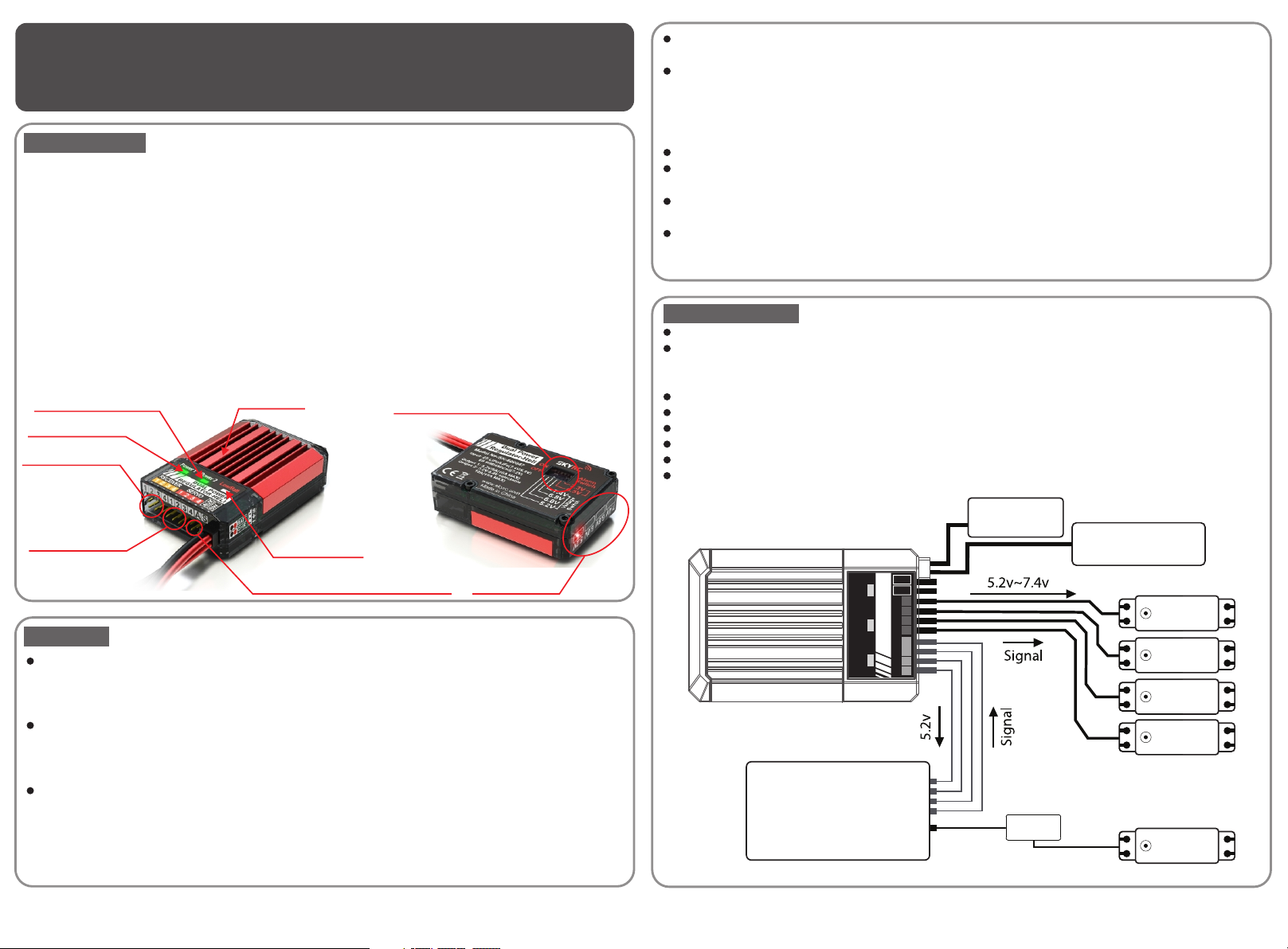
Power 2 LED Indicator
Power 1 LED Indicator
Connect to Receiver
Heat Sink
Voltage DIP Switch
We add Low Voltage alarm to this item and you could choose to use it or not. The voltage which could
be setup is 6.5V or 7.3V due to the characteristics of the battery.
When the battery voltage is below the regulator setup voltage, the Low Voltage Alarm will response, The
LOW/BATT LED and the buzzer will begin to work at the same time. We have also develop an external
LED board with Pin-Flag power switch which can be mounted to the fuselage to perform the Low
Voltage alarm. The high power LED on the external board will be blinking when the voltage is low. So it
is possible to immediately recognize low voltage alarm condition even in day flight.
There are input/output ports for four channels as three servos for CCPM and one for throttle.
It is supported to use 7.4V HV servo. If output voltage is setup to 7.4V or 8.4V(Bypass), it is able to
achieve more stable power supply and transient response than direct connecting 7.4V battery scheme.
Charging and voltage checking cable is integrated for your convenience. You can charge the battery
through that cable.
Dual battery input is supported for advance experience user. If additional battery is connected with
charging and voltage checking cable, two battery powers can be supplied to the regulator in parallel.
(Both battery must be identical, same chemistry, voltage and capacity).
SPECIFICATIONS
Input: 2S LiPo (6 to 8.4Volt)
Dual Output
1. RX Channel 5.2V 5A (Max 10A)
2. Servo Channel 5.2V 6V 6.8V 7.4V 8.4V 10A(Max 15A@6V)
Low Voltage Alarm Setup : LiFe Type(6.5V) LiPo Type(7.3V)
Switch Type : Fail Safe(Fail-Safe-On) Pin-Flag Contactless Type
Power Connector Type : JST Connector Type
Size : 17mm(H) x 40mm(W) x 64mm(L)
Weight : 64g (Excluding Cables)
Contents : Main Unit 1PC, RX Cable 4PCS, Power Switch 1PC, Operating Manual 1PC
Connect to Servo
Low Voltage
LED Indicator
Connect to Pin-Flag Power Switch
Output Voltage
LED Indicator
FEATURES
As DC-DC voltage regulator of linear type is very popular at present, this BEC is also linear regulator
with twin channel. Compared with Switching-type, it will not make switching noise and ripples. What's
more, it could offer stable voltage and current. When radical load change happens, it could response
rapidly. In this case, it is able to work with PPM, PCM but also 2.4G system.
During extreme 3D and F3C flight the current can reach to 8A. The traditional method is battery supply
power to servo through a receiver. In this case, you could not make full effect of the servo. To let the
servo work effectively, we designed this regulator which is applied with reboost power bus to supply
power to servo directly
And according to the traditional way, two same regulators will be packed in one case and the
performance of the electronics, like servo, ESC, gyro can not be fully performed . To improve this, we
use twin output design one is for CCPM servo and the other is for RX and gyro. The circuit of servo
controls the power and responsibility while the circuit of RX and gyro controls the voltage stability and
noise-free. You have five choices of the output voltage 5.2V, 6.0V, 6.8V, 7.4V, 8.4V(Bypass) which can
be set up by DIP switch. As this parameter is stored in it, and extra voltage measurement is not needed.
-1 - - 2-
Power 1 Power 2 Low/Batt
Receiver
DUAL POWER
REGULATOR-HELI
connect
to charger
2S LiPo Battery
SW
AUX
SERVO
1 2 3 4 1 2 3 4
RECEIVER
GYRO
Page 2
INSTALLATION
Setup output voltage of servo channel
1.
The DIP switch which is used to setup the output voltage of servo channel is on the back of the item. There
are four selections 4.8V, 6.0V, 6.8V and 7.4V which can be selected by four switches No 1 to 4 with ON and
OFF position. Please pay attention when switch No.1 to 5 are OFF position, the output voltage is
8.4V(Bypass).
Setup low voltage alarm
2.
The switch No 5-6 is used to set up the low voltage is on the back of the item. The selectable voltage is 7.3V
for LiPo and 6.5V for LiFe. When the battery voltage falls below the regulator setup voltage, the LOW/BATT
LED and the buzzer will begin to work at the same time. If you want to disable the Low Voltage Alarm
function, please turn off both No 5 and 6 switch.
6.8V
6.8V
6.8V
5.2V6.0V
5.2V6.0V
5.2V6.0V
7.4V
Note 1
Factory default setting
7.4V
7.4V
Fully charged battery wouldn’t usually drop to alarm voltage (7.3V for LiPo) for normal servo load at
ambient temperature (22C). Thus is low voltage alarm is active 1 or 2 times after charging,
degradation of battery or wiring condition should be checked. But the cold season, due to the
characteristics of battery, the voltage drops will happen more oftenly. So we suggest you use large
capacity battery or high discharge rate battery in cold season. We also suggest set up the low voltage
to 6.5V in this season.
Note 2
When you set up the low voltage to 7.3V (for LiPo) or 6.5V (for LiFe), the Low Voltage Alarm function
may be activated at 7.2V or 6.4V. The tolerance is about 0.1V. Concerning to different product, the
voltage for Low Voltage Alarm occurs is slightly different.
Sometimes the reverse electromotive force may case Low Voltage Alarm. When a servo motor is
Note 3
connected to the regulator reversely, the servo may move quickly even if the switch is off and the Low
Voltage Alarm will work in this case due to the reverse electromotive force. What's more, the Low
Voltage Alarm is also effected by electromagnetic wave or electromagnetic field. For example, when
the transmitter antenna or oscillator is close to the low voltage alarm circuit, the low voltage alarm will
be activated. Please don't worry when this case occurs and it is not a breakdown and you still could
use this regulator.
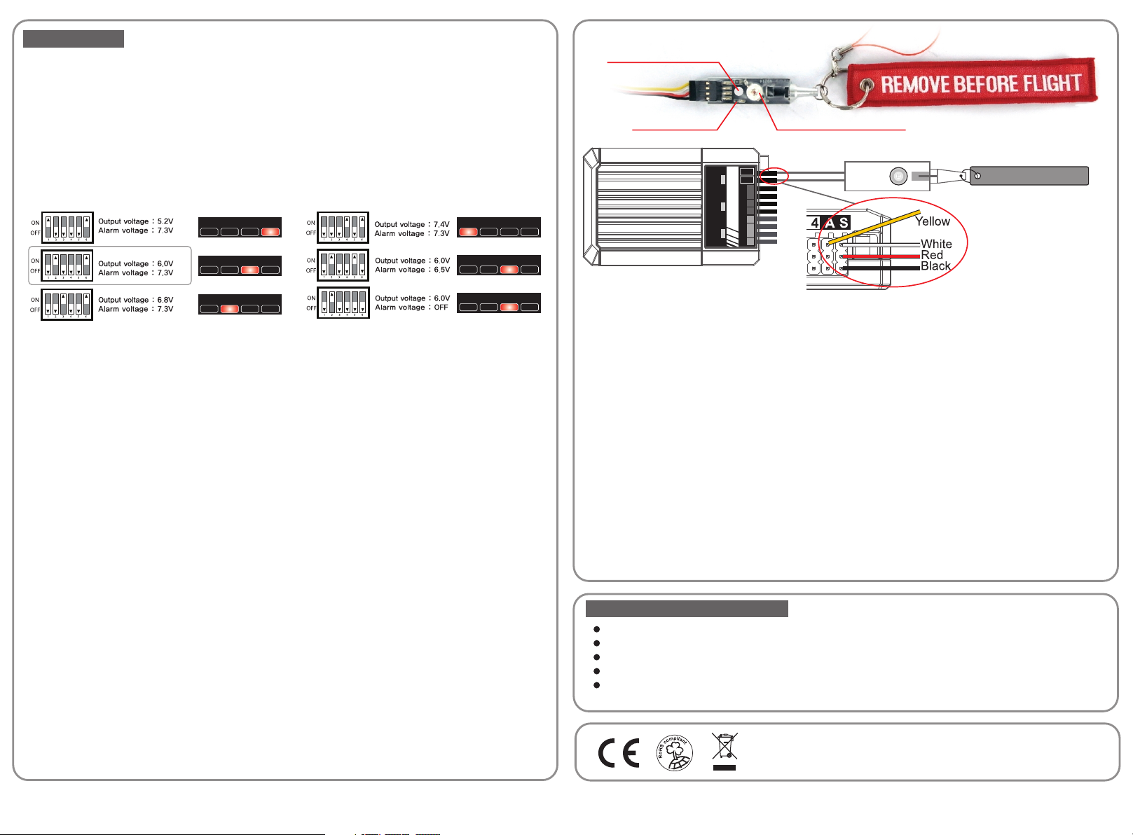
Switch connection
3.
The power switch is Fail-safe-on Pin-flag switch. It could be connected to the SW port of the regulator. When
Pin-flag on the switch board is pulled out, that means the power is turned on.
Note 1
Switch board could be fixed by double-side foam tape or cable. You could also use the hole in the
center of the board and fix it with a 3mm bolt.
Note 2
Even if the switch is off, there is still small current in it. Please disconnect the battery with the
regulator when you don't use it.
Pin-Flag Power Switch
Pin-Flag Power Switch(SK-600052) is an integrated switch which features “Low-voltage alarm LED” .The
power of “Low-voltage alarm LED” is one watt. The high power flux LED Provides day light visibility up to 200
meters away.
It is not necessary to use a switch as the unit uses Fail Safe “On” system, meaning it will automatically power
up when plugged to the batteries if no switch is attached.
7.4V
7.4V
7.4V
6.8V
6.8V
6.8V
3mm Hole for Fixing
Power on LED
5.2V6.0V
5.2V6.0V
5.2V6.0V
Battery connection
4.
The regulator can be connected by JST connectors to the battery. Please make sure the polarity is correct
when you connect the battery. ( If you connect the +/- polarity reversed, internal circuit will be destroyed.)
When charging and checking voltage, you could use female connector. While for dual battery, you could use
male connector to connect battery instead of female connector. After you connect the battery, when you turn
on the switch, if a short sound like beep is heard, that means the Low Voltage Alarm is activated.
Receiver & Servo channel connection
5.
There are four pieces of JR type female-female extension in the box. Please use them to connect the receiver
and the receiver channel on the regulator. The regulator supplies 5.0V voltage to the receiver and the
receiver will respond the signal to the servo channel of the regulator. The servo will respond to the servo
channel of the regulator from CH1 to CH4. In this case, the regulator supply power to the receiver then to
servo.
Note 1
If the four servos are the same, when the operating voltage is the same, the servo channels can be
connected directly.
If the four servos are different, and you use three CCPM (6.0V ) and one throttle servo (4.8V), you need
Note 2
to use a governor with it. What's more, the throttle servo must be connected to the receiver directly.
There are two independent circuits to output to the receiver (5.2V) and to the servo channel (5.2-
Note 3
8.4V). The output voltage is quite different between these two circuits, so if you connect the cables
wrongly, the regulator may not work.
DUAL POWER
REGULATOR-HELI
Power 1 Power 2 Low/Batt
Low Voltage Alarm LED
SW
AUX
SERVO
1 2 3 4 1 2 3 4
RECEIVER
Pin-Flag Power Switch
REMOVE BEFORE FLIGHT
Pin-Flag Power Switch Connection:
Switch Channel (SW)
Signal White wire
+ Red wire
- Black wire
AUX Channel (A)
Low Voltage Signal Yellow wire
WARNING AND SAFETY NOTES
Please find a place with good airflow to install the regulator
Don't put any electronics on the heat sink of the regulator.
Due to the vibration during flight, please make sure the servo, and cable are fixed well to the regulator.
Don't disassemble the regulator by yourself or you will not enjoy our free repair service.
The regulator still consumes small current even if the regulator is OFF. So please disconnect the
battery to the regulator if you don't use it.
Manufactured by
SKYRC TECHNOLOGY CO., LTD.
www.skyrc.com
- 3 - - 4 -
7504-0253-02
 Loading...