

Page 1
19
27
7
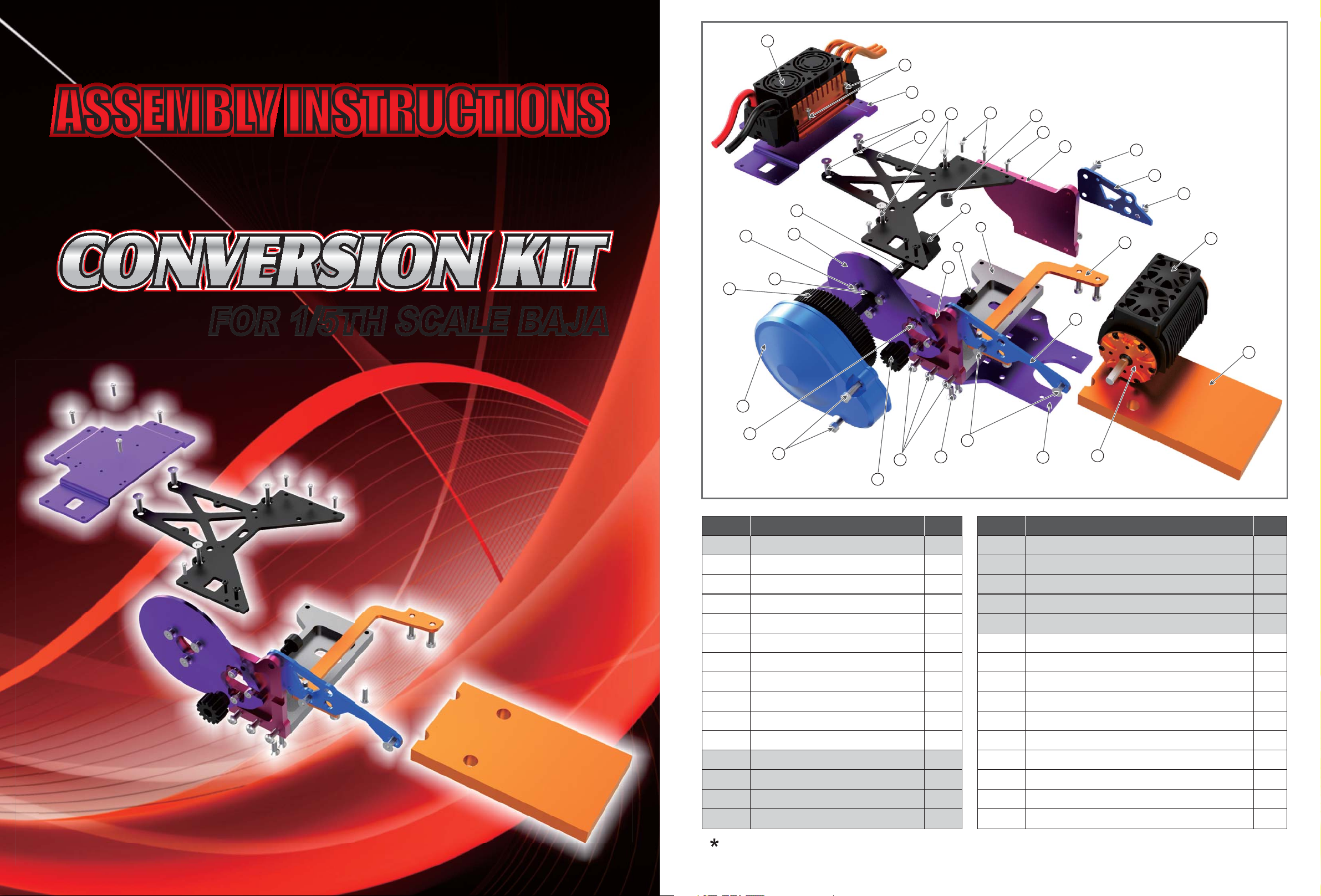
ASSEMBLY INSTRUCTIONS
FOR 1/5TH SCALE BAJA
12
13
21
25
15
29
18
5
24
23
22
6
3
22
28
14
2
26
22
20
27
8
4
1
16
10
22
9
22
17
30
Item No.
1
2
3
4
5
6
7
8
9
10
11
12
13
14
15
11
Description QTY
Baja Stock Car Base Plate*
Base Plate
Motor Mount Plate
Passenger Frame Plate
Gear Cover Plate
Diff Plate
ESC Mount Plate
Motor Mount Plate
Driver Frame Plate
Lateral Brace
14T MOD1.5Pinion
Baja Stock Spur*
Baja Stock Gear Guard*
Baja Stock Part*
12x24x6 Bearing*
Item No.
1
1
1
1
1
1
1
1
1
1
1
1
1
1
1
16
17
18
19
20
21
22
23
24
25
26
27
28
29
30
X528Motor*
Dual Fan Shroud*
Baja Stock Shaft*
1/5 ESC*
Diff Spacer*
M5×10mm Flat Head Cap Screw
M5×16mm Flat Head Cap Screw
M4×30mm Flat Head Cap Screw
M5×16mm Button Head Cap Screw
M4×8mm Socket Head Cap Screw
M8×10mm Socket Head Cap Screw
M3×8mm Button Head Cap Screw
M3×10mm Button Head Cap Screw
M5×20mm Socket Head Cap Screw
Battery Pad
Description QTY
1
1
1
1
1
3
9
2
8
3
1
8
4
6
1
Please note that items with * are not included in the pacakge.
Page 2
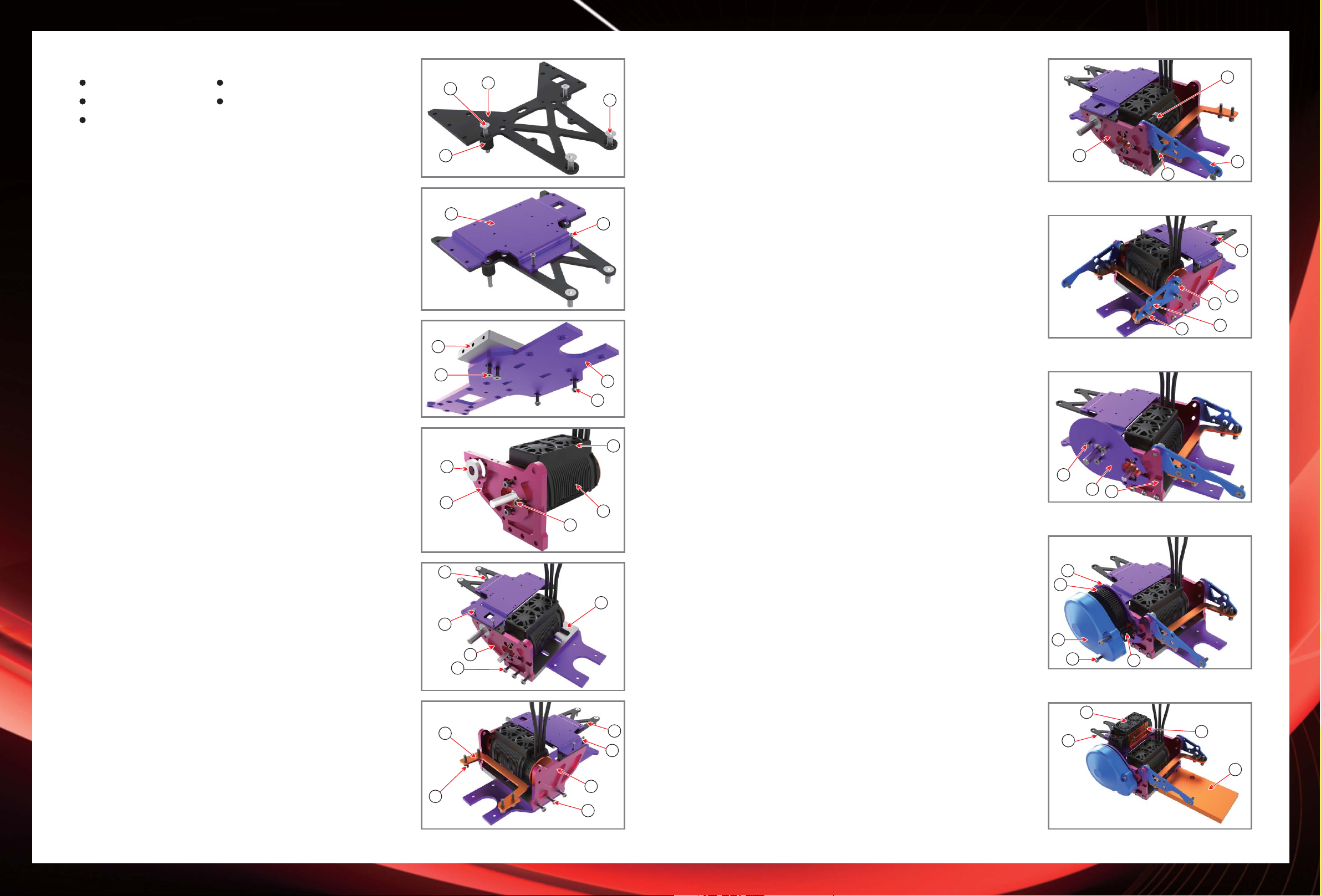
FIGURE 9
FIGURE 10
FIGURE 11
Tools and materials you will need:
2mm hex wrench 3mm hex wrench
4mm hex wrench 6mm hex wrench
green threadlocker
Note:
wait until all parts are assembled before tightening
screws. Refer to Baja manual for gas engine removal
instructions.
1.
Place Diff Plate(item6) to the lower rear shock
brace of the car with two M5×16mm long flat head
cap screws(item22) along with Diff Spacer(item20)
and two M4×30mm long flat head cap screws
(item23) like figure 1.
2.
Connect Base Plate(item7) to the Diff Plate(item6)
by two M3×8mm long flat head cap screws
(item27).
3.
Equip Base Plate(item2) with two M5×16mm Long
flat head cap screws(item22) and two M5×16mm
long button head cap Screws(item24) to the base
plate of the car’s frame(item1) as shown in figure 3.
Put the existing 12×24×6 bearing(item15) from the
4.
vehicle into the corresponding counter bored hole into
Motor Mount Plate(item3) and then mount the X528
motor(item16) to Motor Mount Plate(item3) using
three M4×8mm long socket head cap screws
(item25). See figure 4.
5.
As the bearing facing out, glide it over the car’s drive
shaft and protect the Motor Mount Plate(item3) to
Base Plate(item2) with three M5×16mm long
button head cap screws (item24) and Diff
Plate(item6) with two M3×10mm long button head
cap screws(item28) referring to figure5.
6.
Assemble Lateral Brace(item10) between the frame
and roll cage using four M5×20mm socket head cap
screws(item29). Protect Box Frame Plate(item8) to
Base Plate(item2) with three M5×16mm long
button head cap screws(item24) while Diff Plate
(item6) using two M3×10mm long button head cap
screws(item28). Refer to figure 6.
FIGURE 1
23
20
FIGURE 2
7
FIGURE 3
2
22
FIGURE 4
15
3
6
28
3
24
FIGURE 5
FIGURE 6
10
29
7.
As shown in figure7, use one M8×10mm long
6
22
socket head cap screw(item26) to mount
Passenger Frame Plate (item4) to Motor Mount
26
Plate (item3) and the roll cage using two M5×16mm
long flat head cap screws(item22).
8.
Tighten Diff Plate(item6) with two M3×8mm long
3
FIGURE 7
22
4
button head cap screws(item27). Mount Driver
Frame Plate(item9) to Box Frame Plate(item8) with
27
two M5×16mm long flat head cap screws(item22)
and roll cage with one M5×16mm long flat head
FIGURE 8
27
cap screw(item22). See figure8.
9.
25
24
16
2
Place Gear Cover Plate(item5) onto Motor Mount
Plate(item3) using three M5×10mm long flat head
cap screws(item21) as shown in figure 9.
10.
At present, tighten all screws.
11.
1
17
Replace the spur gear spacer above the drive shaft.
12.
Displace the stock spur gear and “E” clip.
13.
Slide the desired 1.5pinion onto the motor shaft
when the motor mounting screws loose. Make
proper gear mesh. Sliding the motor sideways can
adjust. Tighten the motor mount screws as soon as
FIGURE 9
21
5
3
22
the proper mesh is achieved. You may be able to
slide the pinion off of the motor shaft to obtain the
motor mounting screws.
14.
Adjust the pinion and motor properly, and then you
can align the set screw in the pinion on the flat on
FIGURE 10
5
12
the motor shaft and tighten set screw.
22
8
9
Note: adopt a few of green thread lock between
motor shaft and pinion.
15.
Assemble Gear Guard(item13) onto Gear Cover
13
29
11
Plate(item5) using two M5×20mm long socket head
cap screws(item29).
19
16.
6
28
8
24
Place the 1/5 ESC(item19) onto Diff Plate(item6) with
four M3×8mm long button head cap screws(item27).
17.
Please refer to figure 11 once you finish all of the
steps.
Note: in order to secure your batteries, bind the
Velcro strap across the vehicle’s upper frame rails.
6
FIGURE 11
27
30
 Loading...