

Page 1
INSTRUCTION MANUAL
K V = 4 0 8 4 U = 8 . 2 V
R P M= 3 3 4 9 0 I = 3 . 1 A
K V = 4 0 8 4 U = 8 . 2 V
R P M= 3 3 4 9 0 I = 3 . 1 A
BRUSHLESS MOTOR ANALYZER
SK-500020
FUNCTIONS
KV Measurement
RPM Measurement
Voltage Measurement
Ampere Measurement
Motor Timing Checking
1) Average Timing 2) Phase A, B, C Timing
Noise Level
Hall Effect Sensor Test
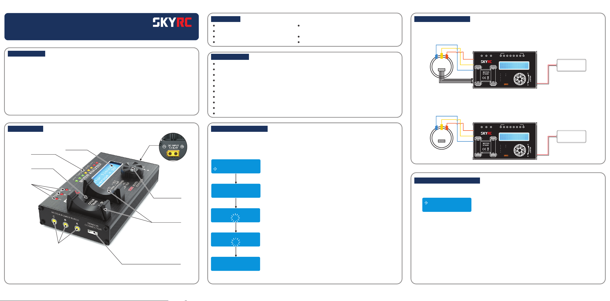
CONNECTION DIAGRAM
Brushless Motor with Sensor
(1) Connect Sensor Cable and Motor Power Wires A, B, C
(2) Connect to Power Source (Reverse Polarity Will Damage This Unit)
INTRODUCTION
Thank you for purchasing the Motor Analyzer BMA-01. We are confident you will find it to be an
indispensable tools you use to make your hobby more funs and enjoyable.
Brushless motors are the most popular motor choice now in the RC Car and model aircraft industry.
With their superior power to weight ratios, a large range of sizes, from under 5 grams to large motors
rated at thousands of watts, they have revolutionized the market for electric-powered model field.
The motor analyzer is a precision electronic device that is especially designed for measuring the KV
value, RMP, current drawn, motor timing, vibration noise level and checking the function of hall effect
sensors of a brushless motor. It comes with a 2X16 characters LCD that is able to display real time
measuring value of either sensor or sensor-less brushless motor.
ILLUSTRATION
Throttle Level
LED Indicators
Noise Sensor
Inside
Hall Effect
Sensors Indicator
Motor Power
Wires Connector
LCD Display
DC Input
7.4-8.4V
Rotary Dial
Motor Stand
Sensor Harness Connector
SPECIFICATION
Input Voltage 7.4-8.4V (Suggested to Use 2S LiPo Battery)
LCD Display Screen: Blue Backlight Background, White Text, 16 Characters X 2 Lines
KV Value Accuracy: +/- 3%
Motor Timing Accuracy: +/- 4%
Motor Timing Range: 0-70°
Noise Level Measurement Range : 60dB - 120dB
Dimension: 136.5mm x 80.6mm x 24.5mm
Net Weight: 282gram (Without Cabel)
Supported Motor: Sensor or Sensor-less Brushless Motor (2 Poles to 36 Poles)
Current Drawn Less Than 30A at 8.4V Without Loading
MOTOR MAGNET POLES
In order to measure the RPM and KV value correctly, you need to select the magnet poles number
according to the motor you are testing. The default values of this motor analyzer for car motor are 2
poles.
For magnet poles other than 2, you need do the setting as follow:
3 . N o i s e L e v e l
4 . P o l e o f M o t o r
Turn Rotary Dial
and press
P o l e o f M o t o r
0 2
Press Rotary Dial again
number of pole will blinking
P o l e o f M o t o r
0 2
Turn Rotary Dial to select
number of pole
P o l e o f M o t o r
1 4
Press again to confirmRotary Dial
number of pole
P o l e o f M o t o r
1 4
THROTTL E LEVEL
MOTOR ANALYZER
KV VOLT
RPM AMP
MOTOR TIMING
NOISE LEVEL
SENSOR TEST
ENTER
START/STOP
LiPo 2 Cells
Battery
A B
Motor
SENSO R
C B A
C
C
B
A
RC Car Brushless Motor without Sensor
(1) Connect Motor Power Wires A, B, C to Motor Analyzer A, B, C
(2) Connect to Power Source (Reverse Polarity Will Damage This Unit)
THROTTL E LEVEL
MOTOR ANALYZER
KV VOLT
RPM AMP
MOTOR TIMING
NOISE LEVEL
SENSOR TEST
ENTER
START/STOP
LiPo 2 Cells
Battery
A B
Motor
SENSO R
C B A
C
C
B
A
CONNECTION PROCEDURES
Connect Motor Analyzer to 7.4V-8.4V power source, the screen will be light up and display will
(1)
show functions selection.
1 . K V R P M U I
2 . M o t o r T i m i n g
For sensor type motor, connect A, B, C wire cable from Motor Analyzer to motor A, B, C connector.
(2)
Please make sure the wires should be connected properly before starting operation.
Wire A: Blue Color
Wire B: Yellow Color
Wire C: Orange Color
Connect sensor harness cable.
1
2
3
Page 2

APPLICATIONS
1. KV / VOLT / RPM / AMP
1 .K V R P M U I
2 .M o t o r Ti m i n g
KV(RPM per Volt) Show the rotor RPM/Volt at a certain throttle power level. The KV rating of
brushless motor is the constant relating the motors unloaded RPM to the peak voltage on the wires
connected to the coils (the "back-EMF"). For example, a 6,768 KV motor, supplied with 7.9 V, will run
at a nominal 53,468 rpm.
U(VOLT) Show the input voltage to motor checker.
RPM(Revolution Per Minutes) Show the rotor revolution at a certain throttle power level.
I(AMP) Show the current drawn by the motor at a certain throttle power level.
The above picture shows the throttle power level. In order to prevent from giving a max power to
the motor from the start up, the default power level is 0 for every time to start running the motor.
The maximum throttle power level is 8.
After you turn Rotary Dial and motor will start running. As the motor is running, the corresponding
parameters will be measured and shown on the display screen.
When the STOP key is pressed, the motor will stop running immediately and the last data measured by
motor analyzer will be recorded and kept on the display screen.
To freewheel the motor at high speed without loading may damage your motor. We suggest you to stop
the motor as soon as the throttle level is reach maximum.
P re s s a n d Tu r n
t o St a r t
Press Rotary Dial again Turn Rotary DialPress Rotary Dial
K V= 0 0 0 0 U =0 . 0 V
R PM = 0 0 00 0 I = 0 .0 A
K V = 6 7 6 8 U = 7 . 9 V
R P M = 5 3 4 6 8 I = 1 . 6 A
K V= 6 7 6 8 U =7 . 9 V
R PM = 5 3 46 8 I = 1 .6 A
Press Rotary Dial (STOP)
2. MOTOR TIMING
MOTOR TIMING: Physical endbell timing, usually between 0 and 70 degrees, requires tools to
rotate the sensor board.
Hall effect
sensor
Timing
0°
20
40
Rotor
Direction
Timing
30°
Hall effect
sensor
40
20
RotorRotor
Timing
45°
Hall effect
sensor
40
20
4 5 6
Average Motor Timing
2 .M o t o r Ti m i n g
3 .N o i s e Le v e l
Use Rotary Dial to
select Motor Timing
M ot o r T i mi n g
P re s s t o S ta r t
M ot o r T i mi n g
Press Rotary Dial Press Rotary Dial
Again and Wait
M ot o r T i mi n g
A ve r a g e = 30
3 seconds
Press Rotary Dial
to hold screen
P h. A P h . B Ph . C
3 0 29 31
Phase A, B and C
Sensor Timing
The performance of the motor is not only related to the endbell timing. It also depend on alignment and
quality of internal parts such as sensor board and rotor.
P h. A P h . B Ph . C
3 0 29 31
Above picture show the actual timing of three sensor elements. This feature shows and measures the
quality of your motor's sensor. Ideally, when the setting of timing on your is 30°, you want the three sensor
elements connected to A, B and C leads to shown exactly same number of degrees. However it is very
difficult to get the same reading in reality world. All manufacturers have variance in the production of
sensors. The values of each A, B and C sensor depends on production batch and how well the sensor chip
is aligned on the PCB. And the distance between sensor and rotor can affect the reading also.
Smaller difference between these values makes a good sensor board.
The Motor Analyzer may not show the same K/V value and Degree of Timing as the manufacturer claims.
The K/V value and Degree of Timing are dependent of many things related to the conditions under which
the motor is running. Motor Analyzer run all motors under the same working conditions and make it easier
to compare between brands and setups.
3. NOISE LEVEL
NOISE LEVEL: Poor assembly motor, inferior bearing and unbalanced rotor can generate a vibration.
Whenever a motor in air vibrates, it causes compression waves in the air. These waves move away from
the motor as sound or noise.
Vibration noise of motor is adverse the performance of motor. By measure the noise level of motors, you
can select the less noise motor.
The decibel (dB) is a logarithmic unit used to express noise level in this motor analyzer.
2 .M o t o r Ti m i n g
3 .N o i s e Le v e l
Use Rotary Dial to
select Noise Level
N oi s e L e ve l
P re s s a n d Tu r n
N oi s e L e ve l
0 40 d B P e ak : 0 4 5d B
Press Rotary Dial Turn Rotary Dial to
Increase Throttle Level
N oi s e L e ve l
0 65 d B P e ak : 0 6 9d B
Show current Noise Level
and Peak Noise Level
4. HALL EFFECT SENSOR TEST (BRUSHLESS MOTOR WITH SENSOR ONLY)
Sensored-type (motors with an extra six wires harness, connected to Hall Effect Sensors). Hall sensors
are commonly used to time the speed of wheels and shafts, such as for internal combustion engine
ignition timing or tachometers. They are used in brushless DC electric motors to detect the position of
the permanent magnet.
After power up the motor analyzer or after the STOP key is pressed to stop the motor running, it will
enter to the Hall Effect Sensor Test mode automatically. If the motor sensor harness is connect to the
sensor connector of the unit, one or two of the sensor LEDs will be light up that show the corresponding
sensors are function correctly.
Rotate the rotor for a step, and then the light up sensor LED will be changed. For example, if the sensor
A LED is light up, after the rotor is rotated by a step, then the sensor A and B LEDs will be fight up at the
same time. If rotating the rotor by a step again, sensor A LED will be light off and sensor B LED will be
light up only.
For a proper sensor operation, LED should be light up according to the below sequence:
A
B
C
LED A -> LED A,B -> LED B -> LED B,C -> LED C -> LED C,A -> this sequence will be repeated if the
hall effect sensors are functioned properly.
The following phenomenons that show the motor Hall Effect Sensor do not work properly.
-The LED light up sequence is not correct
-All LEDs light up at the same time
-All LEDs light off at the same time
SAFETY PRECAUTIONS
Please read the Instruction Manual before starting to operate the motor analyzer. For those users that
do not have experience to use it, please seek help from the professional users.
Please make sure the voltage apply to the unit is within the required range. (7.4V-8.4V) and polarity
should be connected properly.
IF THE INPUT POWER POLARITY IS REVERSED, THE UNIT MAY BE BURNT OUT.
For some high KV motor, long time no loading working is not suggested.
Motor and this unit will generate heat during operation.
ERROR MESSAGE
When the message RUN ERROR is appeared, please check and reconnect the sensor cable and A, B,
C motor wires to the unit again. Make sure A, B, C motor wires are connected to the corresponding A, B,
C socket on the unit. And please make sure there is no short circuit of A, B, C connector. If the error
message still appeared, the tested motor may be failure.
WARRANTY AND SERVICE
We guarantee this product to be free of manufacturing and assembly defects for a period of one year
from the time of purchase. The warranty only applies to material or operational defects, which are
present at the time of purchase. During that period, we will repair or replace free of service charge for
products deemed defective due to those causes.
For any repair or replace service, please contact your dealer in the first instance, who is responsible for
processing guarantee claims. This warranty is not valid for any damage or subsequent damage arising as a
result of misuse, modification or as a result of failure to observe the procedures outlined in this manual.
Manufactured by
SKYRC TECHNOLOGY CO., LTD.
RoHS
www.skyrc.com
2014.12
7504-0532-02
 Loading...