

Page 1
INSTRUCTION
MANUAL
INSTRUCTION
MANUAL
Professional Balance Charger / Discharger
Lithium Battery Meter / Motor RPM Tester /
Servo Tester
Professional Balance Charger / Discharger
Lithium Battery Meter / Motor RPM Tester /
Servo Tester
Version 1.0
Printed in China 2012
All specifications and figures are subject to change without notice.
Manufactured by
SKYRC TECHNOLOGY CO., LTD.
www.skyrc.com
7504-0301-01
Page 2

TABLE OF CONTENTS INTRODUCTION
01
6X80 Plus
Congratulations on your choice of the SKYRC 6x80 Plus digital
intelligent charger from SKYRC Technology Co., Ltd.
The unit is simple to use, but the operation of a sophisticated automatic
charger such as SKYRC 6x80 Plus does require some knowledge on
the part of the user. These operating instructions are designed to
ensure that you quickly become familiar with its functions. It is
therefore important that you read right through the Operating
Instructions, Warning and Safety Notes before you attempt to use your
new automatic charger for the first time. We hope you have many
years of pleasure and success with your new battery charger.
SKYRC 6x80 Plus is a high-performance, micro processor control
charge/discharge station with battery management suitable for use with
all current battery types. With integral equalizer for six-cell, LithiumPolymer (LiPo), Lithium-Ferrum (LiFe) and Lithium-Ion (LiIon) batteries.
Maximum 10A charge current; maximum 80W charge power; can be
powered by a 12 Volt car battery or from 100V-240V via the built in
switch-mode power supply.
When a Nickel battery is fully charged, the unit terminates the process
using the Delta-Peak method. Lithium and lead (Pb) batteries are
charged using the CC-CV method.
The fan cooling system is so smart and efficient. The fan speed is
controlled by internal temperature sensor.
It also adds lithium Batt Meter, Motor RPM Tester and Servo Tester
functions. It is convenient for user to get some useful information with
this charger.
It can be dangerous to mis-handle batteries and battery chargers, as
there is always a risk of batteries catching fire and exploding.
Please BE SURE to read these INSTRUCTIONS, WARNING and
SAFETY NOTES before you use the charger for the first time.
INTRODUCTION......................................................................................................
SPECIAL FEATURES.............................................................................................
WARNING AND SAFETY NOTES.........................................................................
PROGRAM FLOW CHART......................................................................................
LITHIUM BATTERY CONNECTION DIAGRAM ....................................................
OPERATION............................................................................................................
LITHIUM BATTERY PROGRAM..................................(LiPo/LiFe/LiIon) ..................
Charging Lithium Battery at Balance Mode................................................................
Charging of Lithium Battery.......................................................................................
‘FAST' Charging of Lithium Battery............................................................................
'STORAGE' Control of Lithium Battery.......................................................................
Discharging Lithium Battery.......................................................................................
Pb( lead-sulphuric acid) battery program................................................................
Charging of Pb Battery.............................................................................................
Discharging of Pb Battery..........................................................................................
NIMH/NICD BATTERY PROGRAM....................................................... .................
Charging of NiMH/NiCd Battery................................................................................
Charging NiMH/NiCd Battery in The AUTO Charge Mode........................................
Discharging of NiMH/NiCd Battery............................................................................
Charging NiMH/NiCd Battery In Re-Peak Charge Mode..........................................
Charge/Discharge & Discharge/Charge Cycle of NiMH/NiCd Battery.......................
01
03
06
10
12
14
15
15
16
17
18
19
20
20
20
21
21
22
23
23
23
24
BATTERY MEMORY SET......................................................................................
LITHIUM BATTERY METER..................................................................................
MOTOR RPM TESTER..........................................................................................
SERVO TESTER....................................................................................................
SYSTEM SET UP....................................................................................................
VARIOUS INFORMATION DURING THE PROCESS.............................................
WARNING AND ERROR MESSAGE....................................................................
SPECIFICATION.....................................................................................................
RECOMMENDED ACCESSORIES........................................................................
CONFORMITY DECLARATION.............................................................................
WARRANTY AND SERVICE.................................................................................
LIABILITY EXCLUSION........................................................................................
USING THE CHARGE CONTROL SOFTWARE “CHARGE MASTER”..................
27
28
29
30
32
33
34
35
36
37
36
25
Page 3
02
INTRODUCTION
03
6X80 Plus 6X80 Plus
Please read this entire operating manual completely and attentively
before using this product, as it covers a wide range of information on
operating and safety. Or please do use this product in company with a
specialist!
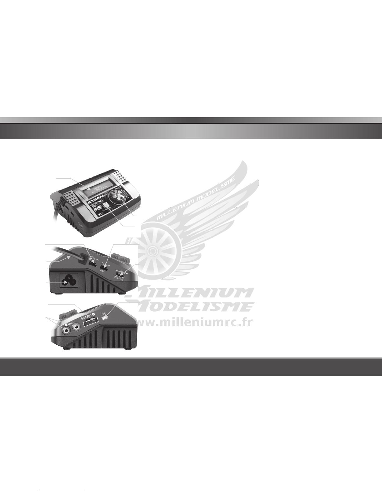
AC Input
Power Port
100-240V AC
DC Input
Power Cable
11-18V AC
Temp.
Sensor
LCD Screen
Enter/Start
Rotary Dial
Mode/Stop Button
Servo/ESC Port
Brushless Motor
Sensor Port
USB Port for PC
Control & Firmware
Upgrade
Battery Socket
Balance Socket
Port Pitch=2.54 mm
SPECIAL FEATURES
Optimized Operating Software
SKYRC 6x80 Plus features the so-called AUTO function that set the
feeding current during the process of charging or discharging.
Especially for lithium batteries, it can prevent the overcharging which
may lead to an explosion due to the user's fault. It can disconnect the
circuit automatically and alarm once detecting any malfunction. All the
programs of this product were controlled through two way linkage and
communication, to achieve the maximum safety and minimize the
trouble. All the settings can be configured by users!
Internal Independent Lithium Battery Balancer
SKYRC 6x80 Plus employs an individual-cell-voltage balancer. It isn't
necessary to connect an external balancer for balance charging.
Balancing Individual Cells Battery Discharging
During the process of discharging, SKYRC 6x80 Plus can monitor and
balance each cell of the battery individually. Error message will be
indicated and the process will be ended automatically if the voltage of
any single one cell is abnormal.
Adaptable to Various Type of Lithium Battery
SKYRC 6x80 Plus is adaptable to various types of lithium batteries,
such as LiPo, LiIon and the new LiFe series of batteries.
Fast and Storage Mode of Lithium Battery
Purposes to charge lithium battery varies, 'fast' charge reduce the
duration of charging, whereas 'store' state can control the final voltage
of your battery, so as to store for a long time and protect useful time of
the battery.
Cyclic Charging/Discharging
1 to 5 cyclic and continuous process of charge>discharge or discharge
> charge is operable for battery refreshing and balancing to stimulate
the battery's activity.
Page 4

04
SPECIAL FEATURES
05
6X80 Plus 6X80 Plus
Data Store/Load
The charger can store up to 10 different charge/discharge profiles for
your convenience. You can keep the data pertaining to program setting
of the battery of continuous charging or discharging. Users can call out
these data at any time without any special program setting.
Terminal Voltage Control(TVC)
The charger allows user to change the end voltage.
Lipo Battery Meter
The user can check battery's total voltage, the highest voltage, the
lowest voltage and each cell's voltage.
Motor RPM Tester
Users connect the sensor motor and charger with sensor wire, set the
pulse width and test the RPM of the motor.
Servo Tester
Connect the servo and the charger with wire, change the pulse width
value and check whether the servo works or not.
Re-Peak Mode of NiMH/NiCd Battery
In re-peak charge mode, the charger can peak charge the battery
once, twice or three times in a row automatically. This is good for
making certain the battery is fully charged, and for checking how well
the battery receives fast charges.
Delta-peak Sensitivity for NiMH/NiCd
Delta-peak sensitivity for NiMH/NiCd battery: The automatic charge
termination program based on the principle of the Delta-peak voltage
detection. When the battery's voltage exceeds the threshold, the
process will be terminated automatically.
SPECIAL FEATURES
Automatic Charging Current Limit
You can set up the upper limit of the charging current when charging
your NiMH or NiCd battery, it is useful for the NiMH battery of low
impedance and capacity in the 'AUTO' charging mode.
Capacity Limit
The charging capacity is always calculated as the charging current
multiplied by time. If the charging capacity exceeds the limit, the
process will be terminated automatically when you set the maximum
value.
Temperature Threshold*
The battery's internal chemical reaction will cause the temperature of
the battery to rise. If the temperature limit is reached, the process will
be terminated.
Processing Time Limit:
You can also limit the maximum process time to avoid any possible
defect.
PC Control Software “Charge Master”
The free “Charge Master” software gives you unparalleled ability to
operate the charger through the computer. You can monitor pack
voltage, cell voltage and other data during the charging, view charge
date in real-time graphs. And you can initiate, control charging and
update firmware from “Charge Master”.
This function is available by connecting optional temperature probe, which is
not included in the package.
*
Page 5
06
WARNING AND SAFETY NOTES
07
6X80 Plus 6X80 Plus
These warnings and safety notes are particularly important. Please
follow the instructions for maximum safety; otherwise the charger and
the battery can be damaged or at worst it can cause a fire.
The allowable DC input voltage is 11-18V DC.
The allowable AC input voltage is 100-240V AC.
Never leave the charger unattended when it is connected to its
power supply. If any malfunction is found, TERMINATE THE
PROCESS AT ONCE and refer to the operation manual.
Keep the charger well away from dust, damp, rain, heat, direct
sunshine and vibration. Never drop it.
This charger and the battery should be put on a heat-resistant,
non-flammable and non-conductive surface. Never place them on
a car seat, carpet or similar surface. Keep all flammable volatile
materials away from the operating area.
Make sure you know the specifications of the battery to be
charged or discharged to ensure it meets the requirements of this
charger. If the program is set up incorrectly, the battery and
charger may be damaged. Fire or explosion can occur due to
overcharging. This warranty is not valid for any damage or
subsequent damage arising as a result of a misuse or failure to
observe the procedures outlined in this manual.
To avoid short circuiting between the charge lead, always connect
the charge cable to the charger first, then connect the battery.
Reverse the sequence when disconnecting.
Never attempt to charge or discharge the following types
of batteries:
A battery fitted with an integral charge circuit or a protection circuit
A battery pack which consists of different types of cells
(including different manufacturers)
A battery that is already fully charged or just slightly discharged
Non-rechargeable batteries (pose an explosion hazard)
A faulty or damaged battery
WARNING AND SAFETY NOTES
Batteries installed in a device or which are electrically linked to
other components
Batteries that are not expressly stated by the manufacturer to
be suitable for the currents the charger delivers during the
charge process
Please bear in mind the following points before commencing
charging:
Did you select the appropriate program suitable for the type of
battery you are charging?
Did you set up adequate current for charging or discharging?
Have you checked the battery voltage? Lithium battery packs
can be wired in parallel and in series, i.e. a 2-cell pack can be
3.7V (in parallel) or 7.4V (in series).
Have you checked that all connections are firm and secure?
Make sure there are no intermittent contacts at any point in the
circuit.
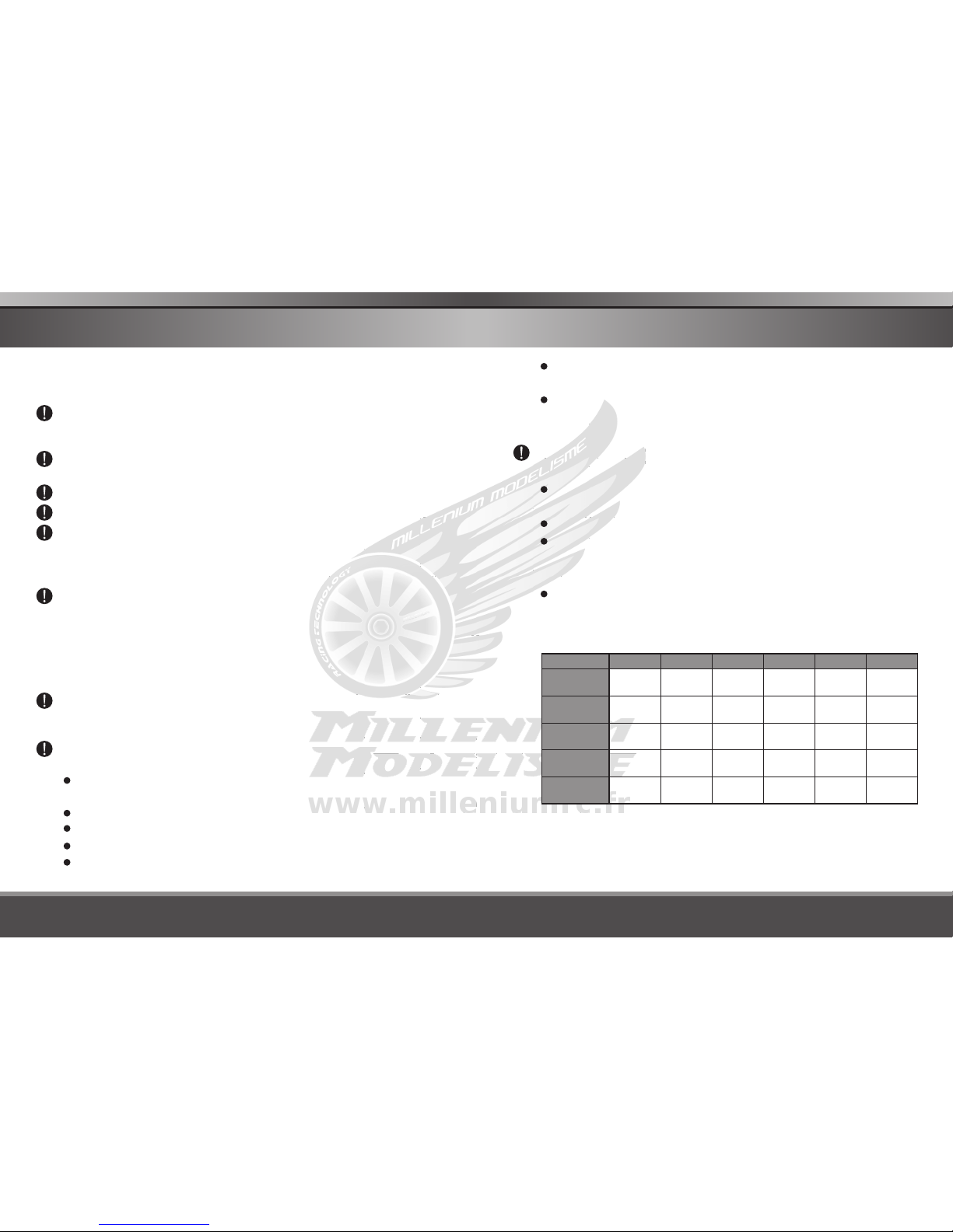
Standar d Ba tt er y Paramet er s
Be very careful to choose the correct voltage for different types of battery otherwise you
may cause damage to the batteries. Incorrect settings could cause the cells to fire or
explode.
3.7 V/cel l
Nom ina l
Volt age
Min. Discharge
Voltage
Max C harge
Volt age
Sto rage
Volt age
Allo wabl e
Fast C harge
3.7 V/cel l
4.2 V/cel l
3.8 V/cel l
≦1C
3.0-3.3V/cell
LiP o
LiI on
3.6 V/cel l
4.1 V/cel l
≦1C
3.3 V/cel l
3.6 V/cel l
3.3 V/cel l
≦4C
LiF e
1.2 V/cel l
1.5 V/cel l
n/a
1C- 2C
NiC d
1.2 V/cel l
1.5 V/cel l
n/a
1C- 2C
MiM H
2.0 V/cel l
2.4 6V/ce ll
n/a
≦0.4 C
Pb
2.9-3.2V/cell 2.6-2.9V/cell 0.1-1.1V/cell 0.1-1.1V/cell
1.8V/cell
Page 6

08 09
6X80 Plus 6X80 Plus
Charging
During charge process, a specific quantity of electrical energy is
fed into the battery. The charge quantity is calculated by multiplying
charge current by charge time. The maximum permissible charge
current varies depending on the battery type or its performance,
and can be found in the information by the battery manufacturer.
Only batteries that are expressly stated to be capable of quickcharge are allowed to be charged at rates higher than the standard
charge current.
Connect the battery to the terminal of the charger: red is positive
and black is negative. Due to the difference between resistance of
cable and connector, the charger can not detect resistance of the
battery pack, the essential requirement for the charger to work
properly is that the charge lead should be of adequate conductor
cross-section, and high quality connectors which are normally goldplated should be fitted to both ends.
Always refer to the manual by the battery manufacturer pertaining
to charging methods. Operate according to their recommended
charging current and charging time. lithium batteries, in particular,
should be charged strictly according to the manufacturer ’s
instruction.
Close attention should be paid to the connection of lithium
batteries.
Do not attempt to disassemble the battery pack arbitrarily.
Please get highlighted that lithium battery packs can be wired in
parallel and in series. In the parallel connection, the battery's
capacity is calculated by multiplying single the battery's capacity by
the number of cells, bearing in mind that total voltage stays the
same. If the voltage is imbalanced, it may cause a fire or explosion.
Lithium batteries are recommended to charge in series.
WARNING AND SAFETY NOTES WARNING AND SAFETY NOTES
Discharging
The main purpose of discharging is to clean the residual capacity
of the battery, or to reduce the battery' voltage to a defined level.
The same attention should be paid to the discharging process as
the charging process. The final discharge voltage should be set up
correctly to avoid deep discharging. Lithium batteries cannot be
discharged to lower than the minimum voltage, or it will cause a
rapid loss of capacity or a total failure. Generally, lithium batteries
don't need to be discharged. Please pay attention to the minimum
voltage of lithium batteries to protect them.
Some rechargeable batteries have a memory effect. If they are
par tly used and recharged before the whole charge is
accomplished, they remember this and will only use that part of
their capacity next time. This is a 'memory effect' It is said that
NiMH and NiCd batteries are suffering from memory effect. NiCd
has more ‘memory effect’ than NiMH.
Lithium batteries are recommended to be discharged partially
rather than fully. Frequent full discharging should be avoided if
possible. Instead, charge the battery more often or use a battery of
larger capacity. Full capacity cannot be reached until it has been
subjected to 10 or more charge cycles. The cyclic process of
charge and discharge will optimize the capacity of battery pack.
Page 7

10 11
6X80 Plus 6X80 Plus
LITHIUM BATTERY CONNECTION DIAGRAM
CONNECTING THE BATTERY
SKYRC 6x80 Plus comes with the built in switching power supply.
You can connect the AC power cord directly to the main AC socket.
(100-240V AC). For attaching directly to 12V car batteries. It is
critically important that you use a fully charged 13.8V car battery.
Important!!! Before connecting a battery it is absolutely essential to
check one last time that you have set the parameters correctly. If the
settings are incorrect, the battery may be damaged, and could even
burst into flames or explode. To avoid short circuits between the
banana plugs, always connect the charge leads to the charger first,
and only then to the battery. Reverse the sequence when
disconnecting the pack.
Using terminal
clip attaching
to car battery
Balance socket:
The balance wire attached to the battery must be connected to the
charger with the black wire aligned with the negative marking. Take
care to maintain correct polarity! (See the wiring diagram below.)
DC INPUT: The maximum charge circuit power is 80W.
AC INPUT: The maximum charge circuit power is 50W.
NOTE:
This diagram shows the correct way to connect your battery to the
SKYRC 6x80 Plus while charging in the balance charge program mode
only.
WARNING:
Failure to connect as shown in this diagram will damage this charger.
LITHIUM BATTERY CONNECTION DIAGRAM
Page 8

PROGRAM SELECT
BATT MEMORY
ENTER
START
BATT MEMORY [1]
ENTER SET
ENTER
START
BATT TYPE
LiPo
BATT VOLTS
7.4V ( 2S )
CHARGE CURRENT
4.9A
DSCH CURRENT
2.2A
DSCH VOLTAGE
3.0V/CELL
TVC=YOUR RISK
4.20V
ENTER
START
ENTER
START
PROGRAM SELECT
SYSTEM SET->
Rest Time
CHG>DCHG 10Min
VERSION
1.00
ENTER
START
SAFETY TIME
ON 120Min
Capacity Cut-Off
ON 5000mAH
Key Beep ON
Buzzer ON
DECINC
Input Power Low
Cut-Off 11.0V
Ext. Temp
Int. Temp 37C
0C
LOAD FACTORY SET
ENTER
STOP
SAVE PROGRAM
ENTER
SAVE PROGRAM
SAVE….
BATT MEMORY [1]
LiPo 7.4V (2S )
ENTER
START
BATT MEMORY [1]
C:4.9A D:2.2A
ENTER CHARGER
LOAD……
LiPo BALANCE
4.9A 7.4V(2S)
LiPo CHARGE
4.9A 7.4V(2S)
LiPo FAST CHG
4.9A 7.4V(2S)
LiPo STORAGE
4.9A 7.4V(2S)
LiPo DISCHARGE
2.2A 7.4V(2S)
BATT MEMORY 2
NiMH 2.4V (2S)
BATT TYPE
MiMH
BATT VOLTS
2.4V (2S)
ENTER
START
CHARGE CURRENT
3.3A
TRICKLE
100mA
PEAK DELAY
1Min
DSCH CURRENT
2.2A
DSCH VOLTAGE
1.1V/CELL
DELTA PEAK SENSE
4Mv/C
SAVE PROGRAM
ENTER
BATT MEMORY 3
Pb 4V (2S)
ENTER
START
BATT TYPE
Pb
BATT VOLTS
4.0V (2S)
CHARGE CURRENT
3.3A
DSCH CURRENT
1.5A
DSCH VOLTAGE
1.7V/CELL
SAVE PROGRAM
ENTER
PROGRAM SELECT
Pb BATT
ENTER
START
Pb CHARGE
2.0A 2.0V (1P)
Pb DISCHARGE
0.1A 2.0V (1P)
PROGRAM SELECT
NiCD BATT
NiCD CHARGE
CURRENT 2.0A
ENTER
START
NiCD DISCHARGE
0.1A CUT: 1.0V
NiCD CYCLE
CHG>DCHG 1
PROGRAM SELECT
NiMH BATT
ENTER
START
NiMH CHARGE
CURRENT 2.0A
NiMH DISCHARGE
0.1A CUT: 1.0V
NiMH CYCLE
CHG>DCHG 1
PROGRAM SELECT
LiPo BATT
LiPo BALANCE
2.0A 7.4V (2S)
LiPo CHARGE
2.0A 7.4V (2S)
LiPo FAST CHG
2.0A 7.4V (2S)
LiPo STORAGE
2.0A 7.4V (2S)
LiPo DISCHARGE
2.0A 7.4V (2S)
ENTER
START
PROGRAM SELECT
Lilo BATT
Lilo BALANCE
2.0A 7.2V (2S)
Lilo CHARGE
2.0A 7.2V (2S)
Lilo FAST CHG
2.0A 7.2V (2S)
Lilo STORAGE
2.0A 7.2V (2S)
Lilo DISCHARGE
2.0A 7.2V (2S)
ENTER
START
PROGRAM SELECT
LiFe BATT
LiFe BALANCE
2.0A 6.6V (2S)
LiFe CHARGE
2.0A 6.6V (2S)
LiFe FAST CHG
2.0A 6.6V (2S)
LiFe STORAGE
2.0A 6.6V (2S)
LiFe DISCHARGE
2.0A 6.6V (2S)
ENTER
START
ENTER
START
PROGRAM SELECT
Li BATT METER
4.20 4.19 4.19 V
0.00 0.00 0.00 V
MAIN 0.00V
H0.000V L0.000V
NiCD RE-PEAK
1
NiMH RE-PEAK
1
NiMH Auto CHARGE
CURRENT 2.0A
NiCD Auto CHARGE
CURRENT 2.0A
TEMPERATURE
CUT-OFF 50C
TEMPERATURE
CUT-OFF 50C
TEMPERATURE
CUT-OFF 50C
SELECT
SELECT
SELECT
SELECT
SELECT
SELECT
SELECTSELECT
SELECT
SELECT
SELECT
SELECT
SELECT
SELECT
SELECT
SELECT
SELECT
SELECT
SELECT
SELECT
SELECT
SELECT
SELECTSELECT
SELECT
SELECT
SELECT
SELECT
SELECT
SELECT
SELECT
SELECTSELECTSELECT
SELECT
SELECT
SELECT
SELECT
SELECT
SELECTSELECT
SELECTSELECT
SELECTSELECT
SELECTSELECT
SELECT
SELECT
SELECT
SELECT
SELECTSELECT
SELECTSELECTSELECTSELECT
SELECT
SELECTSELECT
SELECT
SELECT
SELECTSELECT
SELECT
PROGRAM SELECT
SERVO TESTER
PULSE WIDTH:
700uS
SELECT
PROGRAM SELECT
MOTOR RPM TESTER
PULSE WIDTH:1800
RPM: 00000
SELECT
MODE
ENTER
START
ENTER
START
MODE/STOP
MODE/STOP
SELECT
PROGRAM FLOW CHART PROGRAM FLOW CHART
12 13
6X80 Plus 6X80 Plus
Page 9

OPERATION
The most important tool to operate the charger is the red rotary dial
and black button.
Enter/Start Rotary Dial
Mode/Stop Button
Enter/Start Rotary Dial
The dial has three functions: rotating the dial in both directions will
scroll through menus and adjust parameters quickly and easily, and
pressing down on the dial acts as button which is often used to enter
parameter alert or store parameters on-screen.
Mode/Stop Button
It is used to stop the progress or go back to previous step/screen.
When you are willing to alter the parameter value in the program, press
the dial to make it blink then change the value by rotating the dial
clockwise or counterclockwise. The value will be stored by re-pressing
the dial. When you are willing to start the progress, press and hold the
dial for 3 seconds. When you are willing to stop the progress or go
back to previous step/screen, press the button once.
When you power on the charger, it will enter LiPo Battery balance
program directly. You could change the mode (balance mode, normal
charge mode, fast charge mode, store mode or discharge mode), enter
the desired charging/discharging mode, set the referred parameter and
start the progress.
If you have no request for LiPo Battery program, please press the
button to enter Program Select screen.
14 15
6X80 Plus 6X80 Plus
LITHIUM BATTERY(LiPo/LiFe/LiIon)PROGRAM
These programs are only suitable for charging and discharging lithium
batteries with a nominal voltage of 3.7V, 3.6V and 3.3V per cell. These
batteries need to adopt different charge technique which is termed as
constant voltage(CV) and constant current(CC) method. The charge
current varies according to the battery capacity and performance. The
final voltage of charge process is also very important; it should be
precisely matched with the charge voltage of the battery. They are 4.2V
for LiPo, 3.6 V for LiFe, and 4.1V for Lilon. The charge current and
nominal voltage as for cell count set on the charge program must
always be correct for the battery to be charged.
CHARGING LITHIUM BATTERY AT BALANCE MODE
This function is for balancing the voltage of lithium-polymer battery
cells while charging.
In the balance mode, the battery needs to connect to the battery's
power lead with balance wire.
In this mode, the charging process will be different from ordinary
charging mode. The internal processor of the charger will monitor the
voltages of each cell of the battery pack and control charging current
which is feeding to each cell to equalize the voltage.
Note: We recommend charging lithium batteries with a balance wire in
the balance mode only.
-
-
+
+
Pre ss
Dia l
Mod e
Sto p
> 3 seconds
The left side of the first line shows the type
of battery you choose. The value on the left
of the second line of the charger is current
the user sets. After setting the current and
voltage, press and hold the dial for 3
seconds to start the process.
SELECT
SELECT
Page 10

Number
of
cells
Battery
voltage
Charging
time
Charged
capacity
Charging
current
This screen shows the real-time status during
charge process. Press button once to stop
the charge process.
This screen displays the number of cells you
set up and the processor detects. R shows
the number of cells detected by the charger
and S is the number of cells set by you at
the previous screen. If both numbers are
identical you can start charging process. If
not, press button to go back to previous
screen to recheck the number of cells of the
battery pack before going ahead.
CHARGING OF LITHIUM BATTERY
This charging mode is for charging LiPo/LiFe/LiIon battery in normal
mode.
Note: We recommend charging lithium batteries with a balance lead in
the balance mode only.
-
-
+
+
> 3 seconds
The left side of the first line shows the type
of battery you choose. The value on the left
of the second line of the charger is current
the user sets. After setting the current and
voltage, press and hold the dial for 3
seconds to start the process.
This displays the number of cells you set up
and the processor detects. R shows the
number of cells detected by the charger and
SELECT SELECT
Mod e
Sto p
Pre ss
Dia l
Pre ss
Dia l
16 17
6X80 Plus 6X80 Plus
LITHIUM BATTERY(LiPo/LiFe/LiIon)PROGRAM
Charged
capacity
Number
of
cells
Charging
time
Charging
current
Battery
voltage
S is the number of cells set by you at the
previous screen. If both numbers are
identical you can start charging process. If
not, press button to go back to previous
screen to recheck the number of cells of the
battery pack before going ahead.
This screen shows the real-time status
during charge process. Press button once to
stop the charge process.
‘FAST' CHARGING OF LITHIUM BATTERY
The charging current is getting smaller as the process goes to the near
end term of Lithium battery charging. To finish charging process earlier,
this program eliminate certain period of CV process. Actually, the
charging current will goes to 1/5 from the initial value to end the
process while the normal charging goes to 1/10 during CV period. The
charging capacity may be a bit smaller than normal charging but the
process time will be reduced.
--
++
> 3 sec onds
The value on the left side of the second lines
shows the charge current. The value on the
right side of the second lines shows the
battery pack's voltage. After setting current
and voltage, press and hold the dial for 3
seconds to start the process.
This displays the number of cells you set up
and the processor detects. R shows the
number of cells detected by the charger and
S is the number of cells set by you at the
previous screen. If both numbers are
SELECT SELECT
Mod e
Sto p
Pre ss
Dia l
Pre ss
Dia l
LITHIUM BATTERY(LiPo/LiFe/LiIon)PROGRAM
Page 11

Cur rent
vol tage
bat tery
Sup plied
cap acity
Cha rge
cur rent
Cha rging
tim e
Num ber
of
cel ls
identical you can start charging process. If
not, press button to go back to previous
screen to recheck the number of cells of the
battery pack before going ahead.
This screen shows the real-time status
during charge process. Press button once to
stop the charge process.
'STORAGE' CONTROL OF LITHIUM BATTERY
This program is for charging or discharging Lithium battery which will
not be used for long time. The program will determine to charge or
discharge the battery to certain voltage depending on the voltage of the
battery at its initial stage. They are different from the type of the battery,
3.75V for LiIo, 3.85V for LiPo and 3.3V for LiFe per cell. If the voltage
of battery at its initial stage is over the voltage level to storage, the
program will start to discharge.
-
+
-
+
> 3 seconds
At this screen, you can set up the current
and voltage of the battery pack. Charging
and discharging will make the batteries
come to the voltage level of storage state.
This screen displays the number of cells you
set up and the processor detects. R shows
the number of cells detected by the charger
and S is the number of cells set by you at
the previous screen. If both numbers are
identical you can start charging process. If
not, press Mode/Stop button to go back to
SELECT SELECT
Mod e
Sto p
Pre ss
Dia l
Pre ss
Dia l
18 19
6X80 Plus 6X80 Plus
LITHIUM BATTERY(LiPo/LiFe/LiIon)PROGRAM
Num ber
of
cel ls
Ela psed
tim e
Cha rge
or di schar ge
cur rent
Sup plied
cap acity
Cur rent
vol tage
bat tery
This screen shows the real-time status
charging. Press Mode/Stop button once to
stop the charge process.
previous screen to recheck the number of
cells of the battery pack before going ahead.
DISCHARGING LITHIUM BATTERY
Number
of
cells
-
elapsed
time
+
Battery
voltage
Discharged
capacity
discharge
current
> 3 sec onds
The value of discharge current on the left
can not exceed 1C, and the value on the
ri gh t can not be unde r the v oltag e
recommended by the manufacturer to avoid
over discharging. Press and hold the dial for
3 seconds to start discharging.
This screen shows the real-time status of
discharging, you can press Mode/Stop
button to stop discharging.
This screen displays the number of cells you
set up and the processor detects. R shows
the number of cells detected by the charger
and S is the number of cells set by you at
the previous screen. If both numbers are
identical you can start charging process. If
not, press Mode/Stop button to go back to
previous screen to recheck the number of
cells of the battery pack before going ahead.
Mod e
Sto p
SELECT
-
+
SELECT
Pre ss
Dia l
Pre ss
Dia l
Pre ss
Dia l
LITHIUM BATTERY(LiPo/LiFe/LiIon)PROGRAM
Page 12

20 21
6X80 Plus 6X80 Plus
NIMH/NICD BATTERY PROGRAM
These programs are for charging or discharging NiMH (Nickel-MetalHydride) or NiCd (Nickel-Cadmium) battery.
CHARGING OF / BATTERYNIMH NICD
The charger will charge NiMH and NiCd batteries using the charge
current set by the user.
Ni MH CHAR GE
CU RRENT 2 .0 A
Bat tery
typ e
-
+
Ela psed
tim e
Cha rged
cap acity
Bat tery
typ e
Cha rge
cur rent
Bat tery
vol tage
> 3 seconds
The screen displays the current state of
charging.
To stop the process, press Mode/Stop
button once.
The audible sound indicates the end of
process.
This program is for charging of NiMH/NiCd
batteries. You can press Start/Enter dial to
make the parameter blink, then rotate the
dial to change the value and repress the dial
to store the value.
CHARGING / BATTERY IN THE AUTO
CHARGE MODE
NIMH NICD
In this program the charger detects the condition of the battery which is
connected to the output and automatically charges the battery. In this
mode, you should set up the upper limit of the charge current to avoid
damage by excessive feeding current. Some batteries of low
resistance and capacity can lead to higher current in the auto charging
mode.
N iM H A u t o C H AR G E
C UR R E N T 2 .0A
This program is for charging of NiMH/NiCd
batter ie s in auto mode. You can press
Start/Enter dial to make it blink and then rotate
the dial to change the parameter value. Press
START/ENTER dial to store the value.
SELECT
Mod e
Sto p
Bat tery
typ e
> 3 seconds
Mod e
Sto p
Pre ss
Dia l
Pre ss
Dia l
N iM H 2 . 0 A 9 .52 V
A UT 0 0 0 : 1 3 0 00 0 0
CHARGING / BATTERY IN RE-PEAK
CHARGE MODE
NIMH NICD
Re-peak Charge Mode (NiMH and NiCd batteries only): In re-peak
charge mode, the charger can peak charge the battery once, twice or
three times in a row automatically. This is good for confirming the
battery is fully charged, and for checking how well the battery receives
fast charges. A five minute cool-off delay occurs after each re-peak
charge. To start charge, press and hold the dial for 3 seconds.
NIMH/NICD BATTERY PROGRAM
The screen displays the current state of
charging.
To stop the process, press Mode/Stop
button once.
The audible sound indicates the end of
process.
Ela psed
tim e
Cha rged
cap acity
Bat tery
typ e
Cha rge
cur rent
Bat tery
vol tage
N iM H R E - P E AK
1
N iM H 2 . 0 A 9 .59 V
R PC 0 0 0 : 3 3 0 00 1 7
Re-peak cycle number 1 shows on the display.
Press the dial to make the re-peak cycle
number blink and rotate the dial to find the
desired number of times to re-peak charge the
battery.
Press the dial to confirm selection.
-
+
SELECT
Battery
type
Charge
current
Battery
voltage
Elapsed
time
Charged
capacity
DISCHARGING OF / BATTERYNIMH NICD
Ni MH DISC HA RG E
0. 1A CUT: 1. 0V
Bat tery
typ e
-
+
> 3 sec onds
Set discharge current on the left and final
voltage on the right. The discharge current
ranges from 0.1 to 5.0A and the final voltage
ranges from 0.1 to 25.2V. To start the
process, press and hold Start /Enter dial for
3 seconds.
Mod e
Sto p
SELECT
Pre ss
Dia l
Pre ss
Dia l
Page 13

22 23
6X80 Plus 6X80 Plus
CHARGE/DISCHARGE & DISCHARGE/CHARGE CYCLE
OF NIMH/NICD BATTERY
-
+
-
+
Battery
type
Elapsed
time
Battery
voltage
Discharged
or charged
capacity
Discharge
or charge
current
> 3 sec onds
Ni MH CY CL E
CH G>DCH G 1
Ni MH 1. 0A 7 .42V
C> D 022 :4 5 00890
You can set up sequence on the left and the
number of cycles on the right. Range of the
cycle number is 1-5.
Press Mode/Stop key to stop program, you
can rotate the Start/Enter dial to alter the
current.
Mod e
Sto p
SELECT SELECT
NIMH/NICD BATTERY PROGRAM
Discharge
current
Battery
type
Battery
voltage
Elapsed
time
Discharged
capacity
Ni MH 0. 1A 7 .42V
DS C 022 :4 5 00890
The screen indicates the discharging state.
You can rotate the Start/Enter dial to alter
discharge current and repress the dial to
store the value. Press Mode/Stop button to
stop discharging.
The audible sound indicates the end of
process.
Pre ss
Dia l
PB( LEAD-SULPHURIC ACID) BATTERY PROGRAM
This is programmed for charging Pb (lead-sulphuric acid) battery with
nominal voltage from 2 to 20V. Pb batteries are totally different from
NiMH or NiCd batteries. They can only deliver relatively lower current
comparing to their capacity, and similar restrictions definitely apply to
charge. So the optimal charge current will be 1/10 of the capacity. Pb
batteries must not be charged rapidly. Always follow the instruction
supplied by the battery manufacturer.
CHARGING OF PB BATTERY
Bat tery
typ e
-
Ela psed
tim e
+
Cha rge
cur rent
Bat tery
vol tage
-
+
Cha rged
cap acity
> 3 sec onds
Set up the charge current on the left and the
nominal voltage of the battery on the right.
The charge current ranges from 0.1 to 10.0A
and the voltage should be matched with the
battery being charged. Start the charge
process by pressing and holding the dial for
3 seconds.
The screen displays the state of charging
process. To stop charging forcibly, press
Mode/Stop button once.
The audible sound indicates end of process.
DISCHARGING OF PB BATTERY
-
+
-
+
Set discharge current on the left and final
voltage on the right. The discharge current
ranges from 0.1 to 5.0A.
To start the process, press and hold the
Start/Enter dial for 3 seconds.
SELECT SELECT
Mod e
Sto p
SELECT SELECT
> 3 sec onds
Mod e
Sto p
Pre ss
Dia l
Pre ss
Dia l
Page 14

24 25
6X80 Plus 6X80 Plus
BATTERY MEMORY SET
The charger can store up to 10 different charge/discharge profiles for
your convenience, and the stored profiles can be recalled quickly
without having to go through the setup process.
BA TT ME MO RY【1】
EN TER S ET
BA TT TY PE
Li Po
>3 seconds
Enter the battery memory program, you can
change the battery type(LiPo, LiFe, LiIon, NiMH,
NiCd, Pb battery), voltage, charge current by
pressing the Start/Enter dial to make the value
blink, then rotate the Start/Enter dial clockwise or
counterclockwise to alter the value, and repress
Start/Enter dial to store the value and move to the
next value or screen.
Note:The battery used for this example is a
2S(7.4V) Lipo battery.
DS CH CU RR EN T
2. 2A
BA TT VO LT S
7. 4V( 2S )
CH ARG E CU RR ENT
4. 9A
DS CH VO LT AG E
3. 0V/ CE LL
Set the discharge current, which can be adjusted
(0.1A-5.0A).
Set the discharge voltage, which can be adjusted
(3.0-3.3V/Cell).
Set the voltage and number of cells, along with
the normal voltage (1S-6S).
Set the charge current, which can be adjusted(0.1-
10.0A).
SELECT SELECT
SELECT
SELECT
SELECT
SELECT
SELECT SELECT
SELECT
Pre ss
Dia l
Bat tery
typ e
Ela psed
tim e
Dis charg e
cur rent
Bat tery
vol tage
Discharged
capacity
The screen displays the current state of
discharge. You can alter the discharge
current by pressing Start/Enter dial during
the process. Once you find the desired
current value by rotating the dial, store it by
repressing the dial.
To stop discharging, press Mode/Stop button
once. The audible sound indicates the end
of process.
The free “Charge Master” software gives you unparalleled ability to
operate the charger through the computer. You can monitor pack
voltage, cell voltage and other data during the charging, view charge
date in real-time graphs. And you can initiate, control charging and
update firmware from “Charge Master”.
In order to connect the charger to the computer and use the “Charge
Master”, you are required to use a USB cable which is not included in
this package. The cable must be terminated on one end with “A” plug
and the opposite end is terminated with “mini-B” plug which can
connect to charger directly.
The “Charge Master” can be download from www.skyrc.com. For more
details, please refer HELP file which can be find in “Charge Master”
software.
USING THE CHARGE CONTROL SOFTWARE
“CHARGE MASTER”
USING THE CHARGE CONTROL SOFTWARE
“CHARGE MASTER”
Page 15

TV C=Y OU R RI SK
4. 20V
SA VE PR OG RA M
SA VE
SA VE PR OG RA M
EN TER
>3 seconds
BA TT ME MO RY【1】
Li Po 7. 4V (2 S)
BA TT ME MO RY【1】
C: 4.9 A D: 2. 2A
EN TER C HA RG ER
LO AD… …
next flash
TE MPE RA TU RE
CU T-O FF 5 0C
Set the term in al vol ta ge, which can b e
adjusted(4.18-4.30V).
Save the program set by pressing and holding
the Start/Enter dial for 3 seconds.
This screen indicate the saved profile.
This screen indicates that the charge profile is
being loaded.
Once you've saved a charge profile, you can
load those settings to use later. To load a
memory, you have to press and hold the
Start/Enter dial for 3 seconds. Otherwise you
only enter the setting mode.
SELECT
SELECT
SELECT
SELECT
SELECT SELECT
BATTERY MEMORY SET
Pre ss
Dia l
Set the cut-off temperature, which can be
adjusted(20 C/68 F-80 C/176 F).
26 27
6X80 Plus 6X80 Plus
LITHIUM BATTERY METER
PR OGR AM S EL ECT
Li B ATT M ET ER
Press the Start/Enter dial to enter the Lithium
Battery Meter program.
4. 19 4. 15 4 .1 8V
0. 00 0. 00 0 .0 0V
The screen indicate each cell's voltage.
MA IN 12 .5 2V
H4 .19 0V L 4. 160 V
The screen indicate the total voltage, the highest
voltage, the lowest voltage.
SELECT
The user can check battery's total voltage, the highest voltage, the
lowest voltage and each cell's voltage.
Please connect the battery to the charger main battery lead to battery
socket and balance wires to balance socket.
This diagram shows the correct
way to connect your battery to
check the voltage.
Pre ss
Dia l
4.19 4.15 4.18V
4.15 4.19 4.18V
Page 16

MOTOR RPM TESTER
The charger can test motor RPM. Please do as follows,
Connect the motor and ESC.
Switch off the ESC and connect it to the battery.
Connect the power to the charger.
Insert the ESC signal wire to ESC port in the charger.
Connect the motor and charger with motor sensor wire. There is a motor
sensor port beside the temp sensor.
Enter Motor RPM Tester Program, set the initial pulse width which should be
the same as the neutral position of the transmitter. We suggest to set it to 1480
as most of the transmitters’ neutral position is like that.
Switch on the ESC. Change the pulse width and check the RPM corresponding
to different pulse width. If the motor doesn’t run, please recheck the transmitters’
neutral position and reset the initial pulse width.
Press the Start/Enter dial to enter the Motor RPM Tester
Program and set the initial pulse width by rotating the
Start/Enter knob.
Switch on the ESC.
The left side of the first line shows the pulse width and
the second line shows the RPM of the motor
corresponding to different pulse width. The value of
pulse width can be changed by rotating the Start/Enter
dial.
1.
2.
3.
4.
5.
6.
7.
PR OGR AM S EL ECT
MO TOR R PM T ES TER
SELECT
PU LSE W ID TH :15 00
RP M: 00 00 0
SELECT
This diagram shows the
correct connect way to
test motor RPM.
28 29
6X80 Plus 6X80 Plus
SERVO TESTER
The charger can check whether the servo works. Please do as follows,
Connect the battery to the power.
Connect the servo to the servo port in left side of the charger. Be
careful with the correct polarity.
Enter to Servo Tester Program in the charger, change the pulse
width and check the response of the servo.
1.
2.
3.
Press the Start/Enter dial to enter the Servo
Tester Program.
The screen displays the pulse width. Rotate the
Start/Enter dial to change the value of pulse
width and observe the response of the servo
corresponding to different pulse width
PR OGR AM S EL ECT
SE RVO T ES TER
SELECT
PU LSE W ID TH :
90 0uS
SELECT
This diagram shows the correct connect way to test the servo.
Page 17

SYSTEM SET UP
It will be operated with the default value of the essential user settings
when it is connected to a DC 11~18V battery for the first time. The
screen displays the following information in sequence and the user can
change the value of parameter on each screen.
When you are willing to alter the parameter value, press the dial to
make it blink then change the value by rotating the dial clockwise or
counterclockwise. The value will be stored by repressing the dial.
PR OGR AM S EL ECT
SY STE M SE T
Re st Ti me
CH G>DCH G 10 Mi n
SA FET Y TI ME
ON 1 20M in
User set up starting screen.
The battery is on the cyclic process of charge
and discharge can often become warm after
charge or discharge period. The program can
insert a time delay to occur after each charge
and discharge process to allow the battery
adequate time to cool down before being
subjected to the next process. The value
ranges from 1 to 60 minutes.
When you start a charge process, the integral
safety timer automatically starts running at the
same time. This is programmed to prevent
overcharge the battery if it proves to be faulty,
or if the termination circuit cannot detect the
battery full. The value for the safety timer
should be generous enough to allow a full
charge of the battery.
Safe timer Calculation
When charging NiMH or NiCd batteries, divide
the capacity by current, then divide the result
SELECT
SELECT SELECT SELECT
SELECT SELECT
30 31
6X80 Plus 6X80 Plus
Ca pac it y Cu t-O ff
ON 5 000 mA H
Ke y Bee p ON
Bu zze r ON
Capacity
Current
Safety Time
2000mAh 2.0A
(2000/2.0=1000)/11.9=84 minutes
3300mAh 3.0A
(3300/3.0=1100)/11.9=92 minutes
1000mAh
1.2A
(1000/1.2=833)/11.9=70 minutes
For example:
This program sets the maximum charge
capacity that will be supplied to the battery
during charge. If the deltapack voltage is not
detected nor the safety timer expired by any
reason, this feature will automatically stop the
process at the selected capacity value.
The beep sounds at every time pressing the
buttons to confirm your action. The beep or
melody sounded at various times during
operation to alert different mode changes.
These audible sounds can be on or off.
In put P ow er L ow
Cu t-O ff 1 1.0V
This program monitors the voltage of input
battery. If the voltage drops below the value
you set the operation forcibly terminated to
protect the input battery.
Ex t. Te mp 0 C
In t. Te mp 3 7C
This screen shows the external and internal
temperature.
by 11.9, set this number as the value for
safety timer setting. If the charger stopped at
this threshold, about 140% of the capacity will
have been fed into the battery.
SELECT SELECT
SELECT
SELECT
SELECT
SELECT
SELECT SELECT
SYSTEM SET UP
Page 18

VARIOUS INFORMATION DURING THE PROCESS
VE RSI ON
1. 00
LO AD FA CT OR Y SET
EN TER
Press and hold the Start/Enter dial for 3 seconds
to load the factory set.
This screen shows the version.
SELECT
You can inquire various information on LCD screen during charging or
discharging process. When you rotate the dial counterclockwise, the
screen will display the user’s settings.
And also you can monitor the voltage of individual cell by rotating the
dial clockwise when the individual connection cable is linked to the
Lithium battery being processed.
Ex t. Te mp 0 C
In t. Te mp 2 6C
It comes to the final voltage when the program
ended.
Present input voltage.
This screen shows the internal temperature.
Displayed safety timer is turn on and duration of
time in minutes.
Displayed capacity cut-off function is turn on and
the setting value of capacity.
The battery is connected with balance lead, you
can check voltage of each cell in the battery pack.
VARIOUS INFORMATION DURING THE PROCESS
4.1 9 4. 15 4. 18 V
0.0 0 0. 00 0. 00 V
32 33
6X80 Plus 6X80 Plus
It incorporates a variety of functions for the systems to verify processes
and the state of the electronics. In case of an error the screen will
display the cause of error and emit an audible sound.
Incorrect polarity connected.
The battery is interrupted.
CON NE CT ER RO R
CHE CK M AIN P OR T
The Battery connection is wrong.
The cell number is wrong.
CE LL NU MB ER
IN COR RE CT
Voltage of one cell in the battery pack is too high.
CE LL ER RO R
HI GH VO LT AG E
Voltage of one cell in the battery pack is too low.
CE LL ER RO R
LO W VOL TA GE
The internal temperature of the unit goes too high.
IN T.T EM P. TOO H I
DC I N TOO L OW
Input voltage less than 11V.
Input voltage higher than 18V.
DC I N TOO H IG H
BAT TE RY WA S FU LL
The battery voltage is higher than the maximum
voltage which the user sets when charging in
balance mode.
WARNING AND ERROR MESSAGE
CE LL ER RO R
VO LTA GE -I NVA LI D
Voltage of one cell in the battery pack is invalid.
The external temperature of the unit goes too high.
EX T.T EM P. TOO H I
OV ER CH AR GE
CA PAC IT Y LI MIT
The battery capacity is more than the maximum
capacity which the user sets.
OV ER TI ME L IM IT
The charging time is longer than the maximum
charging time which the user sets.
BA LAN CE C ON NEC T
ER ROR
The balance connect is wrong.
Page 19

SPECIFICATION
SPECIFICATION
(stated values refer to one charger except built-in power supply, dimension & weight)
AC Input
DC Input
Charge circuit power
Charge current range
Discharge current range
Current drain for balancing port
NiCd/NiMH battery cell count
LiPo/LiFe/Lilon cell count
Pb battery voltage
Net weight
Dimension
100-240V
11-18Volt
AC Input 50W
DC 80W Input
0.1-10.0A
8W
0.1-5.0A
200mA/cell
1-15Cells
1-6Cells
2-20V
525g
135x112x60.9mm
Discharge current power
1
2
3
4
THE SET CONTAINS
1. SKYRC 6x80 Plus Charger
2. XH Adaptor
3. Power Cord
4. 18AWG Wire Charging
Cable
34 35
6X80 Plus 6X80 Plus
TP/FP Ada ptor
Temp. Sensor Cable
EH Adaptor XH Adaptor
Dean charging cable
HP/PQ Adaptor
Tamiya charging cable
TRAXXAS charging cable Glow charging cable Crocodile clip charging cable
Futaba RX charging cable
RECOMMENDED ACCESSORIES
SK-600014-01 SK-600020-04
SK-600018-02
SK-600016-03
5201-0030-01
EC3 charging cable
5201-0033-01
5201-0045-01
5201-0034-01
5201-0031-01
5201-0012-01
JST/BEC charging cable
5201-0044-01
5201-0043-01
SK-600005-01
Page 20

WARRANTY AND SERVICE
We guarantee this product to be free of manufacturing and assembly
defects for a period of one year from the time of purchase. The
warranty only applies to material or operational defects, which are
present at t he time of purchase. During that period, we will repair or
replace free of service charge for products deemed defective due to
those causes.
You will be required to produce proof of purchase (invoice or receipt).
This warranty is not valid for any damage or subsequent damage
arising as a result of misuse, modification or as a result of failure to
observe the procedures outlined in this manual.
This symbol means that you must dispose of electrical from
the General household waste when it reaches the end of its useful
life. Take your charger to your local waste collection point or
recycling centre. This applies to all countries of the European Union, and to
other European countries with a separate waste collection system.
devices
36
6X80 Plus
37
This charger is designed and approved exclusively for use with the
types of battery stated in these Instruction Manual. SKYRC accepts no
liablility of any kind if the charger is used for any purpose other than
that stated. We are unable to ensure that you follow the instructions
supplied with the charger, and we have no control over the methods
you employ for using, operating and maintaining the device. For this
reason we are obliged to deny all liability for loss, damage or costs
which are incurred due to the incompetent or incorrect use and
operation of our products, or which are connected with such operation
in any way. Unless otherwise prescribed by law, our obligation to pay
compensation, regardless of the legal argument employed, is limited to
the invoice value of those SKYRC products which were immediately
and directly involved in the event in which the damage occurred.
LIABILITY EXCLUSION
CONFORMITY DECLARATION
Conform
Conform
Conform
Conform
CE-LVD
CE-EMC
EN60335-2-29
FCC
FCC Part 15
Limits-Limitation of voltage charges, voltage fluctuations
and flicker in public low-voltage supply systems, for
equipment with rated current ≤ 16A per phase and not
subject to conditional connection.
Limits-Limits for harmonic current emissions (equipment
input current ≤16A per phase)
El ect roma gne tic c omp ati bil ity -Req uir eme nts f or
hou seho ld ap plia nces ,ele ctri c too ls an d Si mila r
apparaturs - Part 2: Immunity-Product family standard
El ect roma gne tic c omp ati bil ity -Req uir eme nts f or
hou seho ld ap plia nces ,ele ctri c too ls an d Si mila r
apparaturs - Part 1: Emission
EN 55014-1
EN55014-2
Test Standards
Title
Result
SKYRC 6x80 Plus satisfies all relevant and mandatory CE directives and
FCC Part 15 Subpart B: 2008.
The product has been tested to meet the following technical standards:
For safety of household and similar electrical appliances.
Electromagnetic compatibility (EMC), Conduction Emission
& Radiation Emission.
Conform
Conform
EN61000-3-2
EN61000-3-3
 Loading...