

Page 1

1
Nynja Build Manual 1.4d
Nynja Build
manual
Version 1.4d
Page 2
2
Nynja Build Manual 1.4d
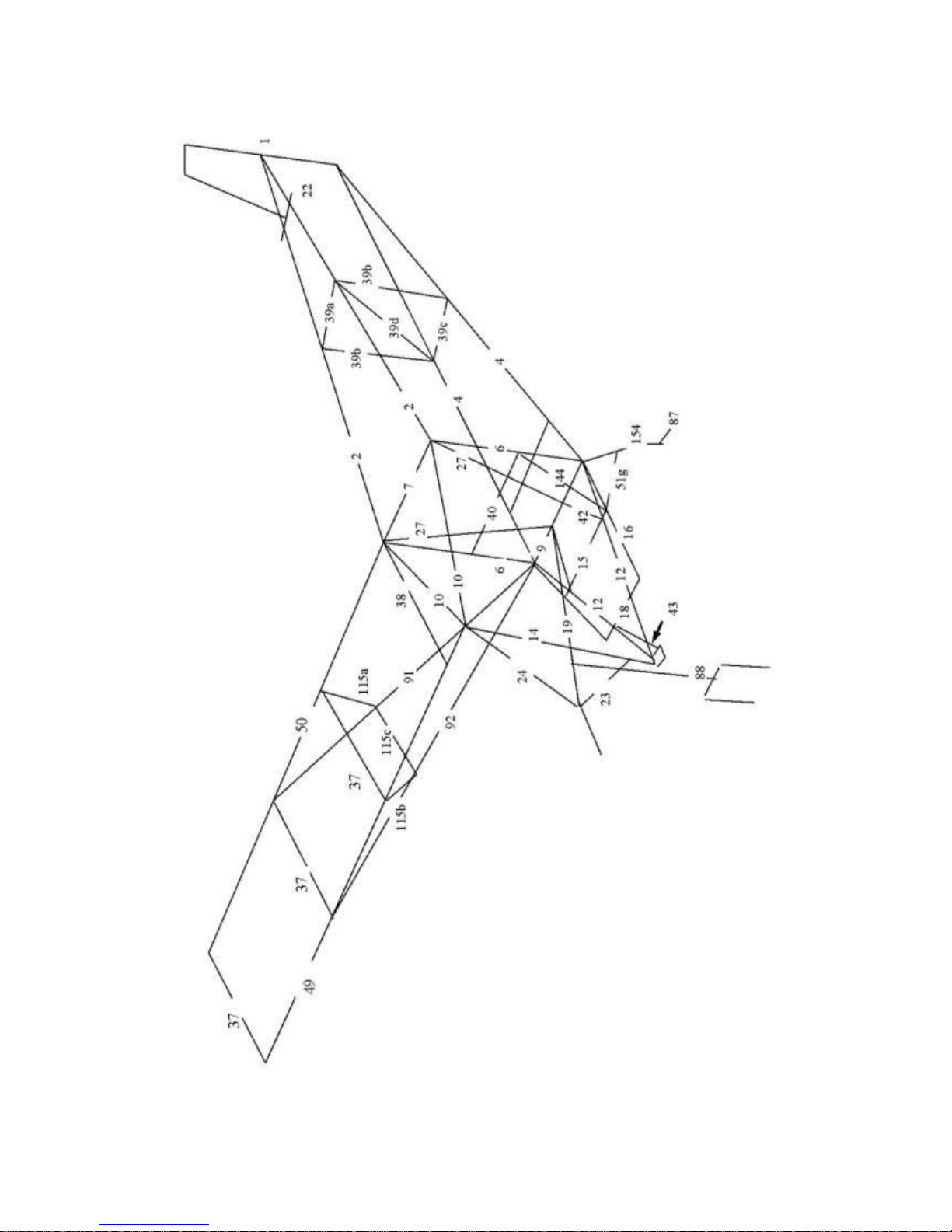
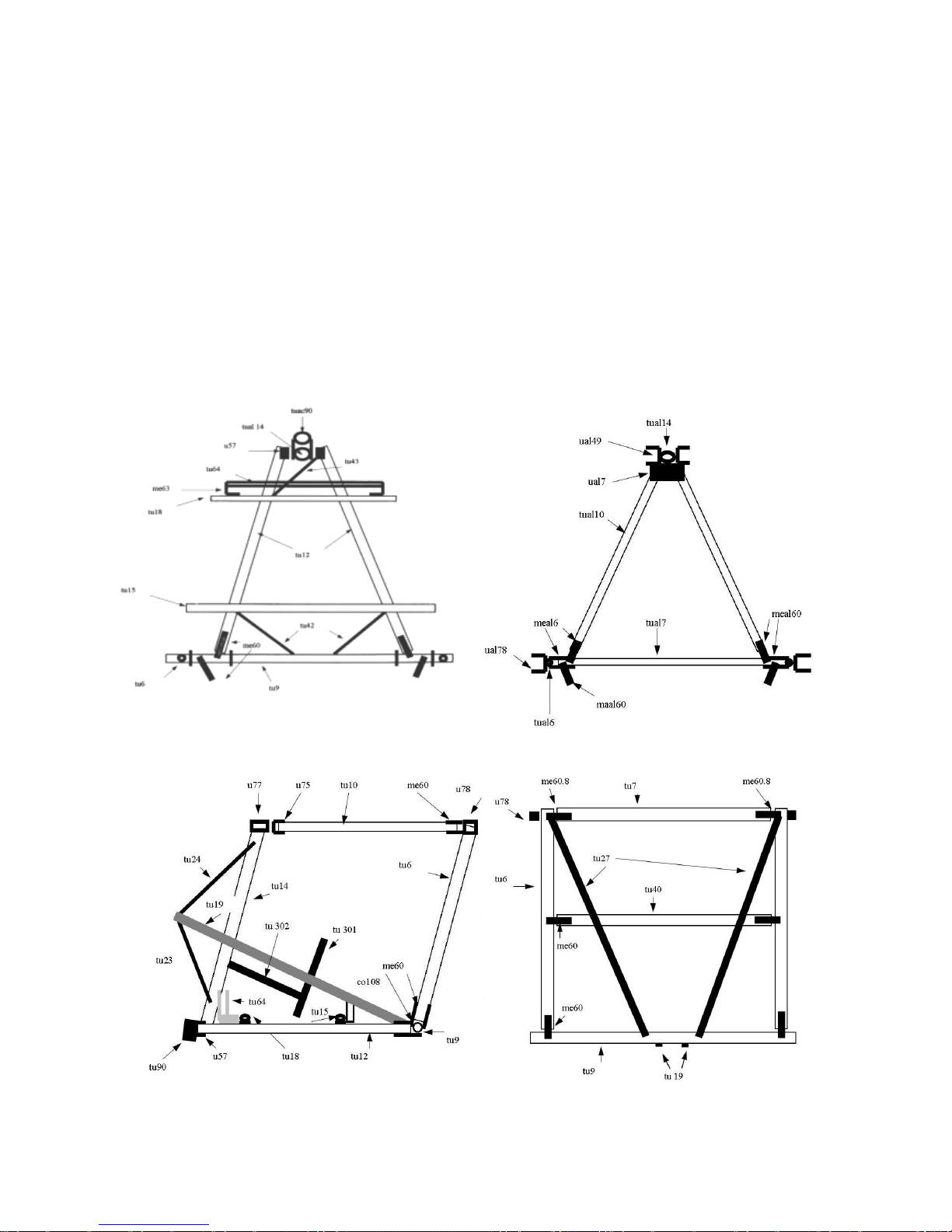
Figure 1 tube numbering scheme.
Page 3
3
Nynja Build Manual 1.4d
Figure 2 Basic frame (Skyranger).
Page 4
4
Nynja Build Manual 1.4d
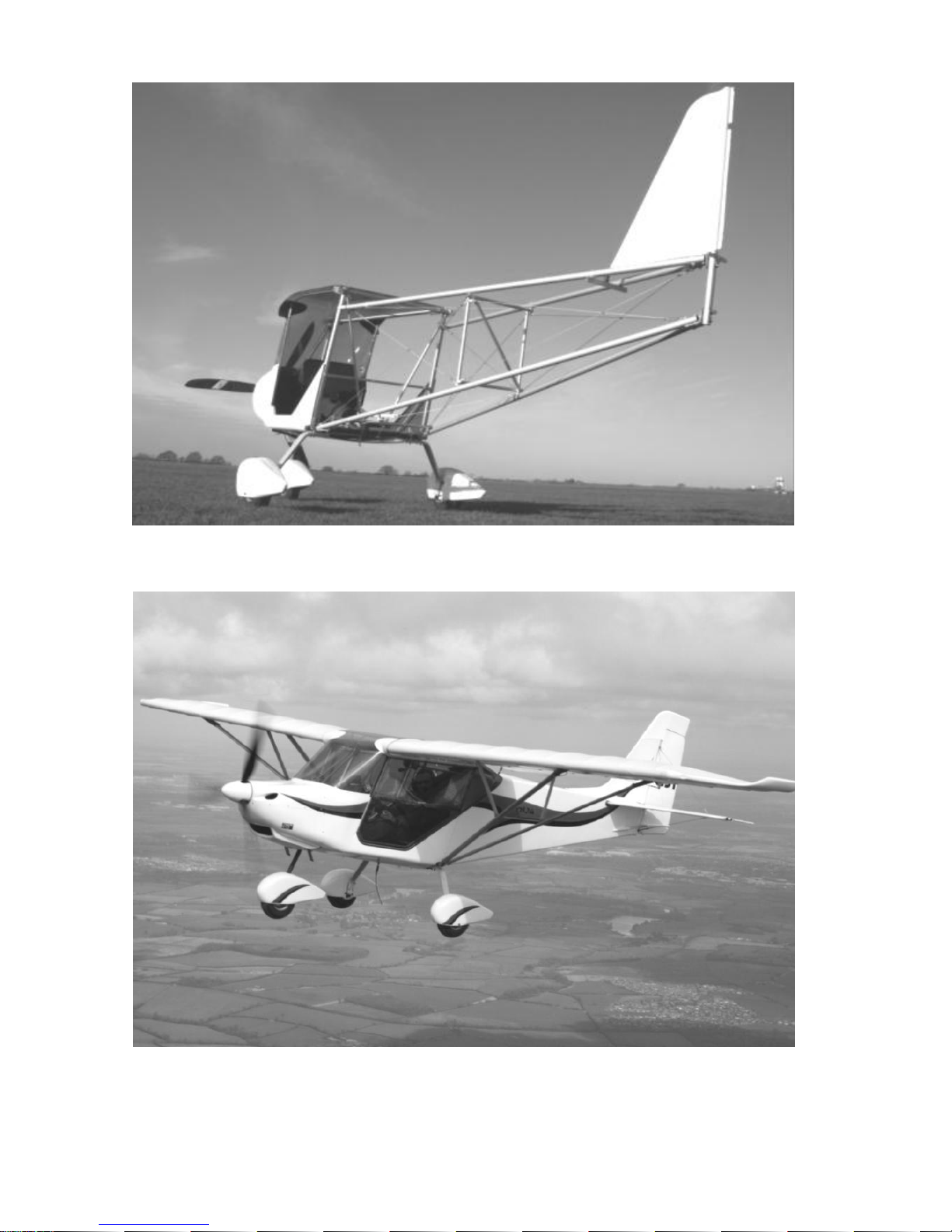
Figure 3 uncovered Skyranger frame.
Page 5
5
Nynja Build Manual 1.4d
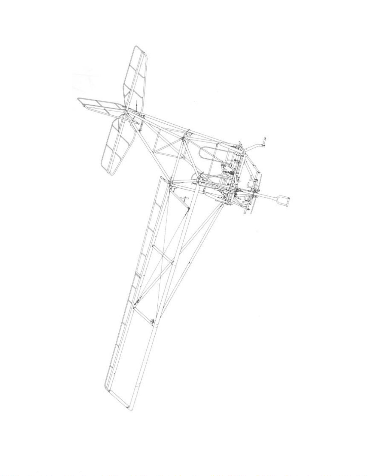
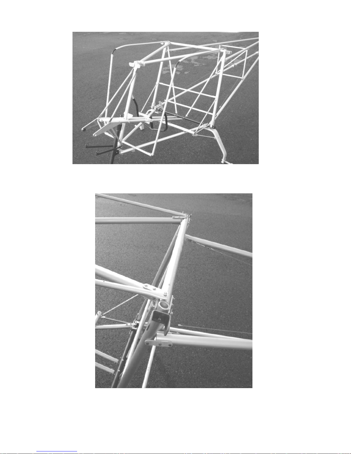
Figure 4 Uncovered Nynja frame
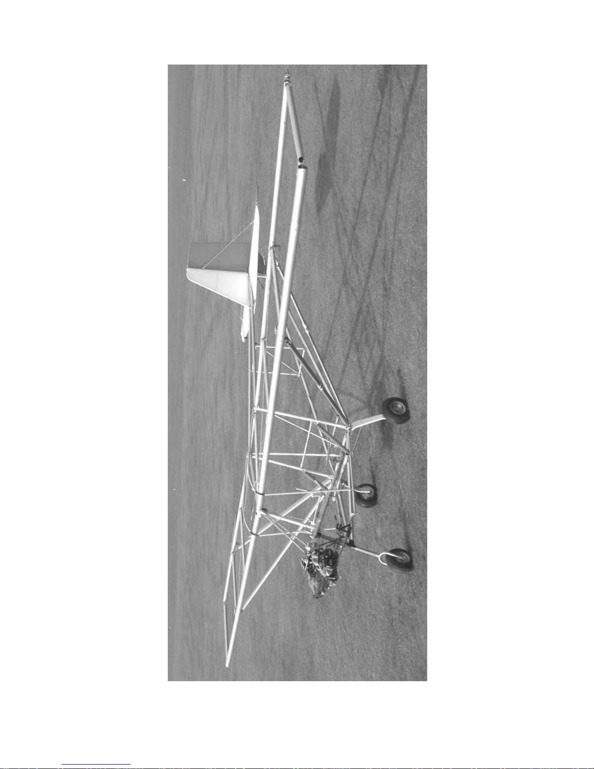
Figure 5 Nynja fuselage with rear fairings removed
Page 6
6
Nynja Build Manual 1.4d
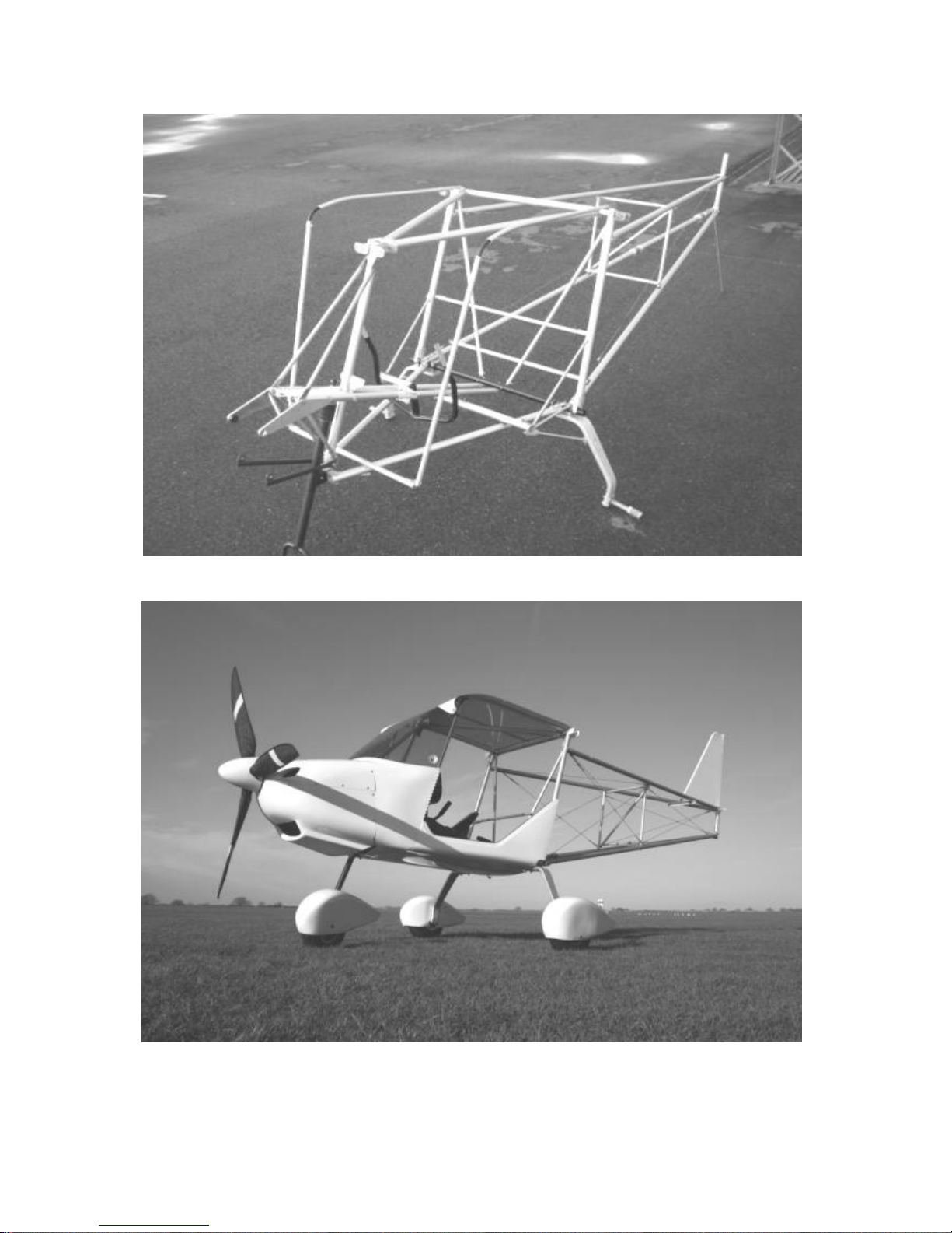
Figure 6 Nynja fuselage with rear fairings removed – rear view
Figure 7 simply assemble thus!
Page 7

7
Nynja Build Manual 1.4d
Contents
Introduction ............................................................................................................. 10
1.1 How to Build Your Aircraft .................................................................................................... 10
1.2 The BMAA Homebuilt Aircraft System ....................................................................................... 12
1.3 General Assembly Notes ........................................................................................................... 14
1.4 Finish .......................................................................................................................................... 18
1.5 Weight ........................................................................................................................................ 20
2. Forward Fuselage ............................................................................................ 21
2.1 Tube Numbering .................................................................................................................. 21
2.2 Fuselage frame assembly overview ........................................................................................... 23
2.3 Lower Cabin Triangle .................................................................................................................. 25
2.4 Upper Cabin Triangle ................................................................................................................. 30
2.5 Rear Cabin Frame ................................................................................................................ 33
2.6 Rear cabin frame bracing. .................................................................................................... 34
2.7 Engine Supports ................................................................................................................... 37
2.8 Floor ..................................................................................................................................... 46
2.9 Rudder Pedals ..................................................................................................................... 48
2.10 Control Stick Assembly ........................................................................................................ 49
2.11 Finishing the Forward Fuselage ........................................................................................... 52
3 Rear Fuselage .................................................................................................. 54
3.1 Tail End ................................................................................................................................ 54
3.2 Bracing Frame ............................................................................................................................. 56
3.3 Front End.............................................................................................................................. 57
3.4 Fuselage bracing cables ............................................................................................................. 58
3.5 Tailplane Front Mounting ..................................................................................................... 63
3.6 Fuel Tank Support and Flap Handle ........................................................................................... 64
Not Tightening the Bolts and cables! ................................................................................................ 66
4 Undercarriage .................................................................................................. 67
4.1 Wheels ................................................................................................................................. 67
4.2 Main Undercarriage .............................................................................................................. 69
4.3 Nose Gear ................................................................................................................................... 73
4.4 Brakes .................................................................................................................................. 77
5. Tail Surfaces ....................................................................................................... 80
5.1 Tensioning the Rear Fuselage ............................................................................................. 80
5.2 Elevator Trim Tab ................................................................................................................. 81
5.3 Tailplane ...................................................................................................................................... 83
5.4 Rudder .................................................................................................................................. 87
5.5 Control Cables ..................................................................................................................... 90
6 Fitting the Rear Fuselage Fairings ............................................................... 100
6.1 Preparing the rear fuselage fairings ................................................................................... 100
6.2 Fitting the rear fuselage fairings ......................................................................................... 101
7. Engine Installation Rotax 912UL/912ULS .................................................... 105
8. Wings .............................................................................................................. 110
8.1 Wing Frame ........................................................................................................................ 110
8.2 Aileron Horn Assembly ....................................................................................................... 119
8.3 Attaching the Wings to the Fuselage ................................................................................. 121
8.4 Aileron Control Cables ....................................................................................................... 122
8.5 Flaps ................................................................................................................................... 126
8.6 Covering the Wings ............................................................................................................ 128
8.7 Inserting the Battens .......................................................................................................... 135
9. Windscreen Frame and Throttles ................................................................. 138
9.1 Windscreen Frame ............................................................................................................. 138
9.2 Throttles ............................................................................................................................. 143
Page 8

8
Nynja Build Manual 1.4d
10. Floor pan, firewall and cowlings .................................................................. 147
10.1 Floor pan ............................................................................................................................ 147
10.2 Firewall and scuttle moulding ............................................................................................. 150
10.3 Engine cowlings ................................................................................................................. 153
11. Engine Ancillaries ......................................................................................... 158
11.1 CKT twin outlet exhaust fitting ........................................................................................... 158
11.2 Oil cooling ................................................................................................................................ 160
11.3 Water cooling ..................................................................................................................... 164
12 Fuel System ................................................................................................... 167
12.1 Fuel lines and connections ...................................................................................................... 167
12.2 Engine compartment ............................................................................................................... 168
12.3 Fuel Tanks............................................................................................................................... 169
12.4 Fitting instructions for HADS Optional Mod 33 – Large diameter balance pipe between fuel
tanks ................................................................................................................................................ 170
Overview ......................................................................................................................................... 170
Parts: ............................................................................................................................................... 170
Fitting ............................................................................................................................................... 171
12.5 Fuel tank load spreader bars .................................................................................................. 172
12.6 Fuel tank securing straps ........................................................................................................ 172
12.7 Fuel tank connections ........................................................................................................ 173
12.8 Fuel filler .................................................................................................................................. 175
13 Instrument panel .............................................................................................. 176
14 Throttle and Choke cables .............................................................................. 180
15 Instruments .................................................................................................... 184
15.1 Pitot-Static System ............................................................................................................. 184
16 Electrical System ........................................................................................... 186
16.1 Soft start wiring .................................................................................................................. 190
16.2 Wiring General Points ........................................................................................................ 191
16.3 Low Current and Instrument Wiring ................................................................................... 191
16.4 Battery ................................................................................................................................ 193
17 Windscreen and rear windows ..................................................................... 195
17.1 Windscreen ........................................................................................................................ 195
17.2 Rear windows ..................................................................................................................... 202
18 Doors .............................................................................................................. 205
18.1 Keeping out the drafts. ....................................................................................................... 205
18.2 One Piece Door .................................................................................................................. 207
18.3 Two Piece Door .................................................................................................................. 213
19 Tail surfaces again ........................................................................................ 224
19.1 Trimmer system ................................................................................................................. 224
20 Centre console. ............................................................................................. 230
21 Seats and Seatbelts....................................................................................... 234
21.1 Seats .................................................................................................................................. 234
21.2 Seatbelts ............................................................................................................................ 237
22 Wheel Spats – Standard ................................................................................ 238
22.1 Nose Wheel ........................................................................................................................ 238
22.2 Main Wheels ...................................................................................................................... 239
23 Fitting the teardrop spat option. .................................................................. 241
Nose Wheel ..................................................................................................................................... 241
Main Wheel spats ............................................................................................................................ 242
24 Fairings .......................................................................................................... 246
Page 9

9
Nynja Build Manual 1.4d
24.1 Lower Fin Fairing ............................................................................................................... 246
24.2 Upper Fin Fairing ............................................................................................................... 246
24.3 Wing Root Fairings ............................................................................................................. 248
24.4 Cable Exit Fairings ............................................................................................................. 248
24.5 Tailplane Leading Edge Fairings ....................................................................................... 249
24.6 Wingstrut end Fairings (Socks) .......................................................................................... 249
24.7 Wingtip Fairings ................................................................................................................. 250
25 Aerofoil Profile Support Blocks ................................................................... 252
26 Fitting the heater option ............................................................................... 254
27 Fitting the storage side pockets................................................................... 256
28 Preparing for Flight ....................................................................................... 257
28.1 Airframe .............................................................................................................................. 257
28.2 Aerofoil Jury struts ............................................................................................................. 257
28.3 General checks .................................................................................................................. 259
28.4 Baggage Bag ..................................................................................................................... 259
28.5 Controls .............................................................................................................................. 260
28.6 Powerplant ......................................................................................................................... 263
28.7 Weight and Balance ........................................................................................................... 265
28.8 Placards ............................................................................................................................. 266
28.9 Test Flying .......................................................................................................................... 266
27 Additional Information .................................................................................... 268
27.1 Example BMAA Homebuilt Registration Form ........................................................................ 268
27.2 Wire-locking........................................................................................................................ 270
28 Index ................................................................................................................. 274
28 Amendments .................................................................................................. 277
Page 10
10
Nynja Build Manual 1.4d
Introduction
1.1 How to Build Your Aircraft
Building the Nynja is a fairly straightforward process, but it can be made much more
difficult than necessary if one basic rule is not followed:
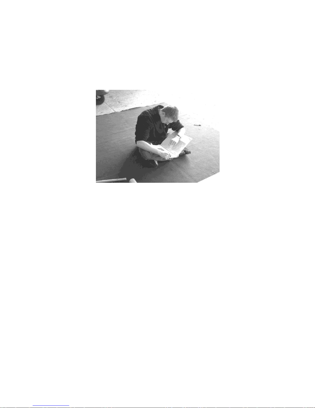
READ THE INSTRUCTIONS!
Figure 8 A rare sight, but essential for successful building (the manual that is, not Rob)!
The Build Manual
Reading the whole manual before starting is suggested. Reading ahead by at least
the section being worked upon, as each section is reached, is recommended.
Reading the instructions for the components under your spanners is essential! It is
remarkable how often the instructions are over-looked or misread, remembering that
you are going to fly in your finished aircraft!
Instructions, however, are never as good as they could be, and so corrections and
suggestions for improving the instructions are welcome, preferably in writing by
email. These can then be included in future updates of the manuals.
If you have errata or receive updates to the manual, mark these immediately in
your copy of the manual so that you do not forget them when you reach that
stage.
An electronic copy of the build manual is available on request via dropbox, and any
updates will be published there as soon as they are made.
Don’t rush things, work carefully, and don’t forget to enjoy building your aeroplane!
Page 11
11
Nynja Build Manual 1.4d
In case of difficulty
If you cannot find a part, ensure that you have determined what it looks like, and that
it is not already attached to a sub-assembly in the area you are working on. Often
parts are hidden by the packaging, or lurking in the bottom of a box of bits in the
corner of the garage, rather than being missing from the kit.
If you have a problem that you cannot resolve by a careful read of the instructions
with the appropriate parts in front of you please have a look in the Skyranger internet
discussion group, send an email, or if all else fails ring:
01604 494459
Note that most enquiries can be answered by a careful read of the manual, so
do give it some thought before calling.
Email is preferred and more convenient than the telephone, as it makes it simple to
communicate answers to other builders and allows time for a better more researched
reply to your questions. Please use paul@flylight.co.uk
Figure 9 We await your call on the Nynja Hotline! – but consider email please!
Photographs
The manual has lots of drawings and photographs to help you build your aeroplane.
The photographs are chosen to illustrate each point, but often include other areas of
the aeroplane in the background. However, due to the number of modifications made
during the UK certification phase you should be cautious about assuming that
background items are shown as they should be on UK specification aircraft. Many
parts are common to the Skyranger and Skyranger Swift, and these may be shown in
some of the photos and drawings where commonality exists.
Page 12

12
Nynja Build Manual 1.4d
1.2 The BMAA Homebuilt Aircraft System
Before starting the build of your Nynja you must register the project with the BMAA.
The required forms are downloadable from the BMAA website at www.bmaa.org, go
to the Technical Information section, click on Forms, and download form
BMAA/AW/022.
An example form for a Nynja fitted with a Rotax 912ULS and standard Kiev prop 283
is shown towards the end of this manual.
You will have to find a BMAA Inspector to oversee the project. A list of Inspectors is
available from the BMAA if required. Fill in the form with information about your
aircraft and Inspector.
Send this form, along with the certificate of conformance for the aircraft, engine and
propeller, with the current fee to the BMAA.
The BMAA will then register the project and issue you with a project number. They
will send you a pack of paperwork with information about building a BMAA homebuilt,
and a stage inspection form to be completed during the build by yourself and your
Inspector.
Please read all the paperwork that the BMAA send you when you receive it –
this may prevent stress later!
You can also register the aircraft with the CAA and order registration letters
(available from Flylight) to save time later.
Your Inspector is required to visit prior to commencing any real building to inspect
your workshop and the kit. This forms the first stage inspection.
Your Inspector has to sign off several key stages of the build. Get his signature on
the form at the time, just in case! He can be a very useful source of knowledge and
advice, and should be your ‘mentor’ during the build. Also, a second pair of eyes and
an experienced mind can often solve problems for you in an instant.
Inspectors will vary somewhat in their likes and dislikes, and so requirements may
vary from what you may consider to be adequate. It is best to listen to your
inspector’s views, but in case of specific queries either you or your inspector may
contact Flylight or the BMAA directly to discuss matters.
Please respect the stage inspections and do not present him with a fully built aircraft
for the first visit! It is not his fault if you have to undo a lot of building to make right
something that should have been checked in a stage inspection before continuing
further. If there is a delay in having an inspection it is better to get on with building
bits and pieces like wheels and wing frames than to continue adding to the main
assemblies.
When your aircraft is complete and to your Inspector’s satisfaction, the completed
stage inspection form is sent to the BMAA. Also required to be sent at the same time
is the Engine Installation Check Sheet (either the Rotax version or the generic BMAA
version for non-Rotax engines). This details tests required to ensure correct
installation and set up of the engine, such as the fuel-flow test described towards the
end of this manual. Again your inspector has to witness the tests and sign the form.
The BMAA will then process the paperwork and raise a BMAA AW029 giving
permission to test fly, along with a draft MAAN (Microlight Aircraft Approval Note) for
Page 13

13
Nynja Build Manual 1.4d
specific clearance and flight testing of your aircraft. This will require checking and
returning to the BMAA for an authorisation signature to make it valid.
Initially your aircraft must be flown by a BMAA Test Pilot, or a specially authorised
check pilot. He/She will fly the aircraft to the flight test schedule to ensure that your
aircraft is set up and flying as it should. You can accompany them for the flight tests
as observer / secretary. When the aircraft is flying satisfactorily (some trimming /
adjustments may be required), then if you have suitable experience you may fly the
aircraft. 5 hours of flying are required to prove reliability and debug the aircraft,
before an application can be made for a full permit to fly. Whilst waiting for this to
arrive you are normally permitted to fly the aircraft, continuing to obey the restrictions
of the test flying clearance contained in the AW029.
If you are the first with a new engine or propeller type, or have made any major
modifications to your aircraft, then 25 hours of reliability testing are usually required.
If you plan any modifications then it is essential that the BMAA is informed at the
beginning of the project, so that a technical investigation can be made and approval
for you to go ahead can be given.
It is likely that you are keen to begin construction, and are waiting impatiently for the
paperwork and your inspector to allow you to do so. However, this short delay can be
used very productively to familiarise yourself with the instructions and the
components, and prepare them for use.
Modifications
You may desire to install equipment such as a radio, strobes etc.. These will
constitute modifications to the standard aircraft and therefore must be done in
accordance with BMAA procedures. Details of the most common modifications are
included in the TIL’s, and Standard Minor Mods (SMM) available on the BMAA
website ( www.bmaa.org ) . If these are done at the time of construction no additional
modification fees are payable.
For modifications not covered by the TIL’s, or SMM’s, it is probably better to
complete the standard aircraft and commence flying before proceeding with the
modification. This is because non-standard modifications will introduce complexity
and delays into getting you aircraft flying, and so these are best done at leisure when
you already have your aircraft in the air.
Note that the Nynja succeeds in providing a capable aeroplane at an excellent price
by following the principle of simplicity. Some areas may look basic at first glance, but
meet the stringent requirements of BCAR Section S without adding cost and weight.
Any modifications you make must also meet Section S, but it is up to you how much
cost you are willing to bear and where you spend your weight. However, increased
cost and less fuel carrying capacity are difficult to avoid.
Do not begin any modifications without first speaking to your inspector, the
BMAA, or Flylight Airsports.
Page 14

14
Nynja Build Manual 1.4d
1.3 General Assembly Notes
Before starting to assemble anything, read the whole of this manual to get an overall
impression of the order and methods of assembly. The sequence of construction is
the one used to build the importer’s aircraft, and should be adhered to. If you wish to
change the sequence, you may find difficulty in fitting other parts later, so read ahead
carefully to determine the effects of your changes. Flylight Airsports cannot advise
on, nor be responsible for, the consequences of not following the instructions, as if
we have not tried something we cannot comment upon it with any experience.
Unpacking
To familiarise yourself with the kit components it is useful to unpack the kit and sort it
into groups for each assembly stage, such as wing parts, fuselage parts,
undercarriage etc.. Do this in conjunction with the packing list and the instruction
manual to determine that you have all the required parts.
If you cannot find a part, check under the packaging on related assemblies,
and make sure you know what it is that you are looking for, as parts may be
rolled up or transported inside other parts. For instance smaller tubes may be slid
inside larger ones.
Don’t forget to check all the boxes, in case you’ve put a box aside somewhere. Some
small parts may be hidden within packaging foam ‘snow’ in the bottom of boxes, so
don’t throw any boxes or packaging away until you have ascertained for certain that
you have all the parts – we have stories of unloading skips to retrieve parts that have
gone with the rubbish!
We also pack some parts in the engine box – so remember to look in there.
This may all sound obvious, but we know from past experience that even big parts
like propellers can be thought missing when they are there all the time!
Don’t try and remove the glassfibre parts from the big wood box without first
removing at least one of the metal side rails on the box – or the gap will be too
small and you will flex and crack the big side panels!
Initial assembly with non locking nuts
During initial assembly it may be helpful to use wing nuts or normal nuts (wing nuts
are preferred as they are more obvious and less likely to be forgotton!) rather than
Nyloc nuts for test fitting pieces, or on pieces which need to be removed later to fit
the coverings or other parts. Alternatively, only tighten the Nyloc nuts up to the Nyloc
section until ready to apply threadlock and tighten properly.
Assembly
If in doubt about a part, or an assembly, read ahead and pay particular attention to
drawings and photographs. Note that the direction of bolts (up/down, pointing
forwards/backwards) may differ between drawings and photographs. Normally, the
bolts will be inserted from the top or the front, unless other considerations apply,
such as coverings or access.
Remember to replace any non locking nuts with Nyloc nuts before final assembly,
and also:
REMEMBER TO USE LOCTITE 243 ON ALL NUTS.
Page 15

15
Nynja Build Manual 1.4d
This is usually available from your local fastenings company, look them up in the
Yellow Pages under “Fixings and Fasteners”, and you will never be stuck for nuts
and bolts again!
Loctite should be used very sparingly. A common mistake is to overuse it. Loctite
smeared over the outside of fasteners acts as a corrosive agent. Any surplus should
be immediately removed with a soft cloth.
A good tip is to paint a red stripe across the nut and bolt end after final tightening.
This way it will be easy to inspect and spot any nuts not finally tightened.
Main tools needed for assembly
Spanners and sockets in the range of: 6, 8, 10, 12, 13, 14, 17mm
Allen keys: 4, 6, 8mm
Metal saw
Drill and bits for metal
Rivet pliers
Cutting pliers
General pliers
Screwdrivers, flat and cross-head
Hammers, metal and rubber/plastic
Mouse tail file with diameter less than 6mm
Flat file
Engineers Rule
Tape measure
6mm reamer (desirable)
Wire-locking pliers (desirable)
Cleco’s or Skin pins for 4mm holes
Dremel Multi tool or equivalent small cutting / sanding tool
Soft faced clamps
Rivnut installation tool and 4 and 5mm Rivnuts (these can be really useful to make a
tidier alternative to nuts or captive nuts on things like instrument panel fixings)
Products needed for assembly
Loctite 243, to be used on all bolts
Silicon grease
Oil for general use
Oil for engine and gearbox, see engine documents
Epoxy adhesive (Araldite or similar)
Lock-wire
Holes
All the holes have been drilled to a high accuracy, however it may sometimes be
necessary to use a round file or reamer to ease the insertion of some bolts. Be
careful not to make a hole too large however, sometimes all that is required is to
loosen other bolts nearby, or to apply pressure to some other part. Generally bolts
should not be tightened up until all the parts in a particular sub-assembly are
assembled, to avoid the common problem of the final bolt not fitting!
Page 16

16
Nynja Build Manual 1.4d
Washers
Metal washers should be used to prevent scratching of the surface as a nut is
tightened.
Nylon washers, or similar plastic washers, should be used to:
a) fill spaces between parts, such as between tubes and U-brackets
b) avoid friction between two moving metal parts, such as the stick and its
supporting bracket
c) avoid contact between parts of different materials, especially stainless-steel
and aluminium
The final point above is primarily to prevent the hard steel wearing through the soft
aluminium due to vibration, rather than for electrolytic reasons, as the bolt passing
through both materials will still complete the electrical connection.
Saddle washers
Normally they are shown on the drawings and photos.
Generally they are used between two crossed tubes or between a tube and a flat
bracket.
Take care not to overtighten bolts which pass through plastic saddle washers as you
may cause them to split.
Nuts and washers
Standard nuts and washers in the main kit are metric zinc plated steel. An acceptable
alternative is to use A2 stainless nuts and washers. These can be purchased from a
fastener supplier for relatively low cost and provide protection form corrosion. Note
that bolts supplied are a mix of 8.8, 10.9 and 12.9 and Eastern European Mil spec
and some smaller bolts are stainless steel. These may NOT be changed for other
specification or to stainless steel as strength, malleability and dissimilar metal
corrosion can be problems.
Bolts
Generally all bolts should bear on their unthreaded lengths, not on the threaded
portions.
It is also important that nuts are not screwed on so far as to become ‘threadbound’
by reaching the limit of the threaded portion. You can use an extra washer or two to
adjust the effective length and prevent this where required.
Turn nuts, not bolts whenever possible, when tightening, as this may damage the
plating and encourage corrosion. Washers are only needed under nuts to allow them
to be turned, whereas bolt heads should not be turned.
Do not over-tighten bolts, avoid deformation of tubes or brackets.
Page 17
17
Nynja Build Manual 1.4d
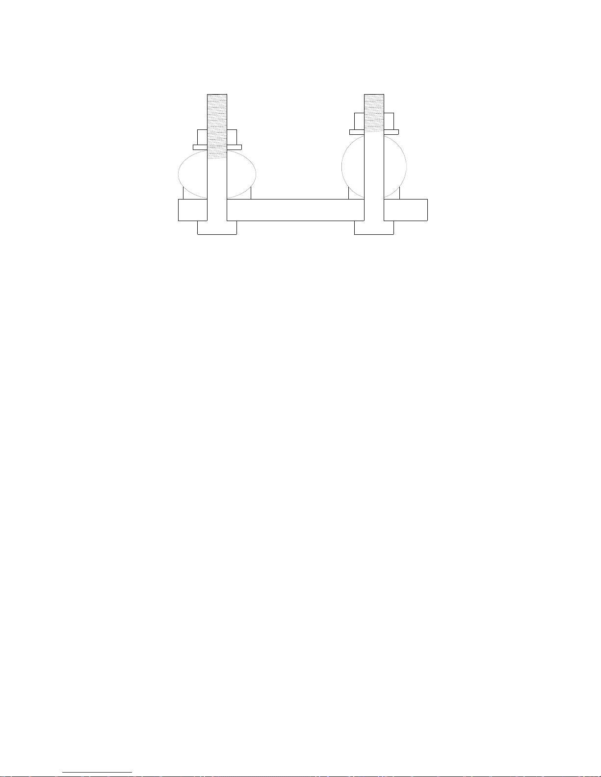
IMPORTANT: tubes must not be visibly deformed.
Figure 10 Left - WRONG – squashed tube, thread in tube. Right – RIGHT – tube still round,
thread stops in washer(s).
Every wing nut has to be fastened by a security ring or aviation ‘nappy pin’.
Nyloc nuts should be used only once.
When cutting bolts short, a minimum of two threads should protrude from the nut.
Paint the cut end to prevent rusting.
Bolts subject to rotation should be drilled and locked with a split pin. Examples
include stick pivot bolt, torque-tube pivot bolt, rudder link bolts.
Wire-locking
Certain parts require securing with lock-wire, such as engine bolts and turnbuckles. If
you have not done this before, discuss how to do it with your inspector. A basic guide
to wire-locking bolts and turnbuckles is included at the end of this manual.
Stainless-steel parts
A number of tubes have flattened steel end-fittings which may require slight “tweaks”
to align them as required. This should be done carefully in a vice, with wooden jaw
pieces to protect the surfaces.
Avoid bending the parts back and forth repeatedly, and avoid bending them at
the hole position.
The finish on the stainless-steel parts is quite varied. If desired these parts can be
polished to a shiny finish, although those positioned in the pilot’s line of sight may be
covered in anti-reflection black coatings or plastic sleeving if desired. Scotchbrite
pads can be used to provide a pleasing, even, cosmetic finish.
Coverings
Handle the coverings with care, pay attention to the risk of bolt heads, corners and
reinforcements/stiffeners damaging the covering as it is put on.
Dacron coverings need care to avoid getting dirty and becoming stained. Keep your
hands and tools clean and oil-free when working with or near these coverings.
Page 18

18
Nynja Build Manual 1.4d
You can remove most dirty marks on Dacron with a sponge soaked with tepid water
and a mild detergent, followed by rinsing using only tepid water.
Part numbering
Numbers in bold italics refer to a part number, either as shown on the relevant
drawing or a universal part number with a prefix. Prefixes refer to the following:
tu tube
tual aluminium tube
tuac steel (acier in French) tube
u U-bracket
ual aluminium U-bracket
me metal plate piece
meal aluminium metal plate piece
meac steel (acier) metal plate piece
ca cable, wire rope
The material-type part of the number is not always used.
During assembly follow the drawings and photographs corresponding to the text.
Drilling and cutting
When drilling holes or cutting parts be very careful to measure and mark the correct
positions. Check these a second time before proceeding to cut or drill.
The old adage of measure twice, cut once still applies!
Otherwise, you won’t be the first to ring up to order a new bit, having chopped
something too short!
If you find a part which you think is wrong, in terms of size etc., be very sure that this
is so before cutting or drilling etc. to correct the problem. For instance, over-long
bolts may have extra parts to be fitted later. Leave irreversible actions until the end of
the build!
When drilling holes in metal, use a centre punch to prevent the drill wandering, and
start with a small pilot drill working up to the required hole size.
It can be useful to use masking tape on fibreglass gel surfaces to help prevent
cracking, and to reduce the risk of marking the surface if the drill should slip.
1.4 Finish
All Aluminium parts are supplied anodised or powder coated. Do not be alarmed if
some marks are present in the finish of the tubular parts, this is a result of the
suspension method at the anodising plant. You may also notice areas on tubing that
may appear to have fine sanding marks. This is done prior to the anodising process
to polish out any small scratches. It is also not unusual to find small areas of silver
paint applied at the final stage over any small remaining marks prior to leaving the
factory. Some light scuff marks may be present as a result of storage and transit.
Page 19

19
Nynja Build Manual 1.4d
This is normal. Deep scratches or dents are not acceptable – ask you inspector for
advice, and refer the problem to the importer.
Aluminium plate parts may be painted to improve their cosmetic appearance if
desired. Use a Scotchbrite pad or lightly sand with fine wet and dry before using a
suitable aluminium primer and top coat. Ensure that all painting operations result in a
thin covering that will not hide defects from inspection.
Steel components are all supplied plated and / or powder coated, for corrosion
resistance. Again they may be painted for extra protection or cosmetic reasons if
desired.
Further protection from corrosion can be beneficial for longevity, and to resist the
ravages of operation near the sea or storage in damp hangars. Aluminium and steel
parts can be treated with corrosion protection products such as the excellent ACF50.
This should be squirted in all tube ends and around fittings and applied to the outside
with a soft cloth. An initial thorough application before covering is recommended
(don’t do this if you have Dacron covers that you intend to paint), followed by periodic
repeat application.
‘Wax oil’ or similar propriety products may also be used inside tubes and around
fittings.
Glassfibre fairing parts are supplied in a white finish. This can be polished with T cut
or similar to a high sheen. Alternatively they can be painted, but avoid using dark
colours on the rear fuselage fairings as strong sun can generate high temperatures
that will soften the glass fibre. None of the fairings carry structural loads so this does
not have any safety implications, but this may result in cosmetic damage in the form
of permanent distortion / waves in the fairings.
Self adhesive vinyl graphics may be applied, but again avoid large areas of dark
colour.
Dacron coverings may be lacquered with a special process using Automotive
Polyester or Acrylic Lacquer mixed with a flex agent. Refer to the importer for more
information. Advantages are stronger colours and a sealed shiny finish which allows
oil etc to be wiped off without leaving marks. Disadvantages include extra weight and
the loss of the ability for the coverings to be re-used in the event of removal for
damage repair.
Xlam coverings can be decorated with Vinyl graphics. Take care to degrease the
surfaces prior to application and use good quality Vinyl with good adhesive
properties. Application in low temperatures is to be avoided, and some work with a
heat gun and application of pressure will be required to work the Vinyl into the weave
and stitching to ensure good long term adhesion. Seek specific advice before
application.
Page 20

20
Nynja Build Manual 1.4d
1.5 Weight
The UK prototype Nynja with Xlam coverings, Rotax 912ULS and standard ‘console’
dash, basic analogue instrument fit, installed intercom box, aerial and radio, and
including doors (see note below***), has been found to have a basic empty reference
weight of approximately 258kg. Options such as, wheel spats, spinner, thick carpet,
etc will have a weight penalty. Painting metal parts, cowlings and applying lacquer to
Dacron coverings will have a weight penalty. Additional avionics or strobes are also
surprisingly heavy.
It may be necessary to make choices in these options to ensure that the weight
remains inside the maximum permitted Zero Fuel weight (ZFW) for the aircraft. The
ZFW will vary according to the fuel burn of the chosen engine option. Max ZFW for
the 912ULS engine Nynja is 268Kg
Refer to the Homebuilt Aircraft Data Sheet (HADS) or the BMAA for further
information on the rules regarding weight for this class of aircraft.
Below is an approximate guide to the weight of specific options:
Wheel spat kit + 4.0Kg
Nynja wingtip fairings + 2.0Kg
Skyranger wing tip fairings (alternative to above) +1.5Kg
Carb heat (912 engines) +0.7Kg
Heater option + 1.0Kg
Spinner +0.5Kg
912UL engine - 1.5Kg
Slipper Clutch on 912/912ULS gearbox +1.5Kg
Large starter motor on 912 / 912ULS +0.5Kg
****Items that are non essential for flight and are easily removable may be eligible for
non inclusion in the ZFW calculation and be considered as payload. These items
may include:
Baggage hammock 1.5Kg
Doors 5.5Kg
Other items may be eligible – See latest version Of HADS or refer to BMAA.
If a total aircraft parachute recovery system is fitted, then the max permitted MTOW
rises to 472.5Kg and Max ZFW also rises 22.5Kg to 290.5Kg. These systems can
typically be installed for around 12 - 15kg, allowing the remainder of the allowance to
be used for payload, or additional fixed items.
Weight is surprisingly cumulative and dividends will be gained by ‘thinking light’
during every stage of the build. The benefits of an aircraft kept well under the
maximum permitted weight will be better performance and payload capacity.
Page 21
21
Nynja Build Manual 1.4d
2. Forward Fuselage
Note: During assembly of the fuselage, hand tighten the bolts only as far as the
Nyloc section. After the fuselage is complete and you are sure it is correct, you
can go back and tighten all of the nuts.
If you wish plain nuts, or even better wing nuts, can be used in the initial construction,
to be replaced with Nylocs when the time comes to tighten the nuts up. However,
note that it is often beneficial to have the nuts loose anyway, to ease any alignment
difficulties.
2.1 Tube Numbering
Refer to these drawings for tube numbers throughout the forward fuselage assembly
sequence.
Figure 11 cabin lower and upper triangle tube numbering.
Figure 12 cabin viewed from port side, and rear cabin frame viewed from rear.
Page 22
22
Nynja Build Manual 1.4d
Figure 13 forward fuselage from front quarter.
Figure 14 Cabin upper rear corner
Page 23
23
Nynja Build Manual 1.4d
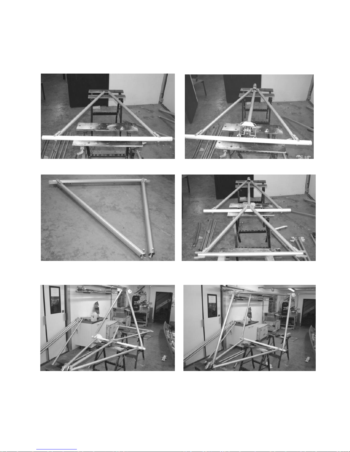
2.2 Fuselage frame assembly overview
Lower triangle assembly Attaching TU14
Upper triangle assembly Attaching upper triangle to TU14
Attaching rear cabin uprights TU6 Attaching Upper triangle to uprights
Page 24
24
Nynja Build Manual 1.4d
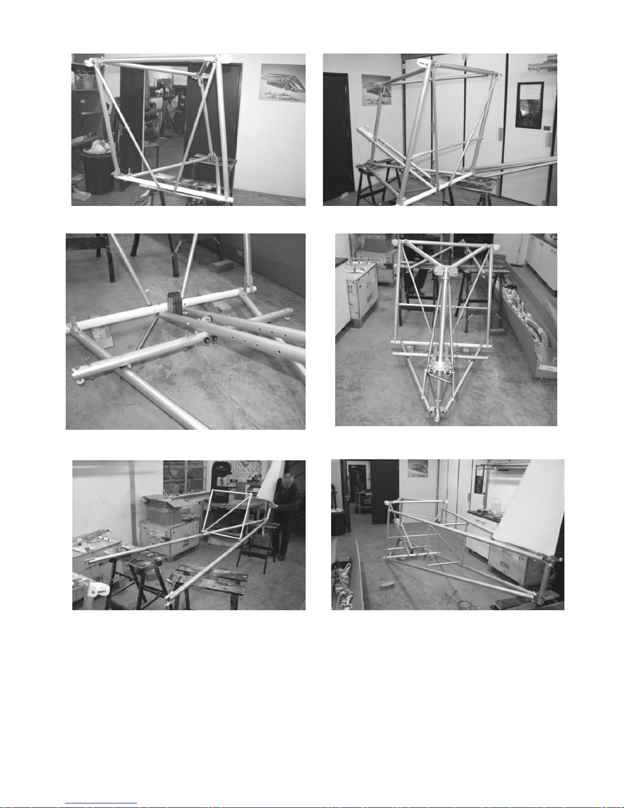
Cabin diagonals TU27 attached Twin TU19 tubes in position
Front seat support TU15 and braces Forward engine mount assembly fitted
Assembling tailcone Tailcone fitted to cabin
Figures 15 – assembly overview
Page 25

25
Nynja Build Manual 1.4d
2.3 Lower Cabin Triangle
2.3.1 Orienting the main undercarriage cross-beam tu9.
The main undercarriage cross-beam tu9 is made of steel.
Flip the beam over until satisfied that the holes are in the correct positions.
The holes in the steel main undercarriage cross-beam tu9 are drilled at
an angle through the beam so that the tail section of the fuselage,
which attaches to the third set of holes in from the ends, tilts upwards
from the beam whilst the lift-strut attachment bolts, nearest the ends,
remain horizontal.
Figure 16 Tu9 (The big white tube), looking from above, front of aircraft to left
2.3.2 Fitting the sides of the lower cabin triangle to the main
undercarriage cross-beam.
a) Assemble the aluminium linking plates 9 onto the pair of lower cabin triangle
tubes tu12, including the seat support brackets (Figure17)
The linking plates are drilled with three 6mm holes, not at equal
intervals. The centre hole is offset away from the single mounting hole.
Remember the anti-crush spacers on the bolts (inside the tubes).
The middle bolts have the seat support bracket, an L-shaped piece, on
their upper ends, with the upstanding part of the bracket in front of the
bolt. A piece of fuel tube may be slit to fit over the support, and secured
with silicone sealant, to make a better rest for the seat base later.
The bolts should pass from bottom to top (contrary to the drawing, but
as per the photographs), to clear the undercarriage legs later.
Page 26

26
Nynja Build Manual 1.4d
11,,,SKR.254
Figure 17 lower cabin triangle, rear of tube tu12 (note, find SKR254 in assembly bag A9)
b) Assemble the pair of lower cabin triangle tubes tu12 to the main undercarriage
cross-beam tu9 using the fourth set of holes inwards from the ends of tu9.
The front ends of the lower cabin triangle tubes tu12 should have the
cut-outs on the inside, visible in Figure 19.
Bolt spacers are not needed in the steel undercarriage tube.
The bolts should pass upwards, to clear the undercarriage legs later.
Figure 18 starboard end of tu9, looking from front.
Page 27
27
Nynja Build Manual 1.4d
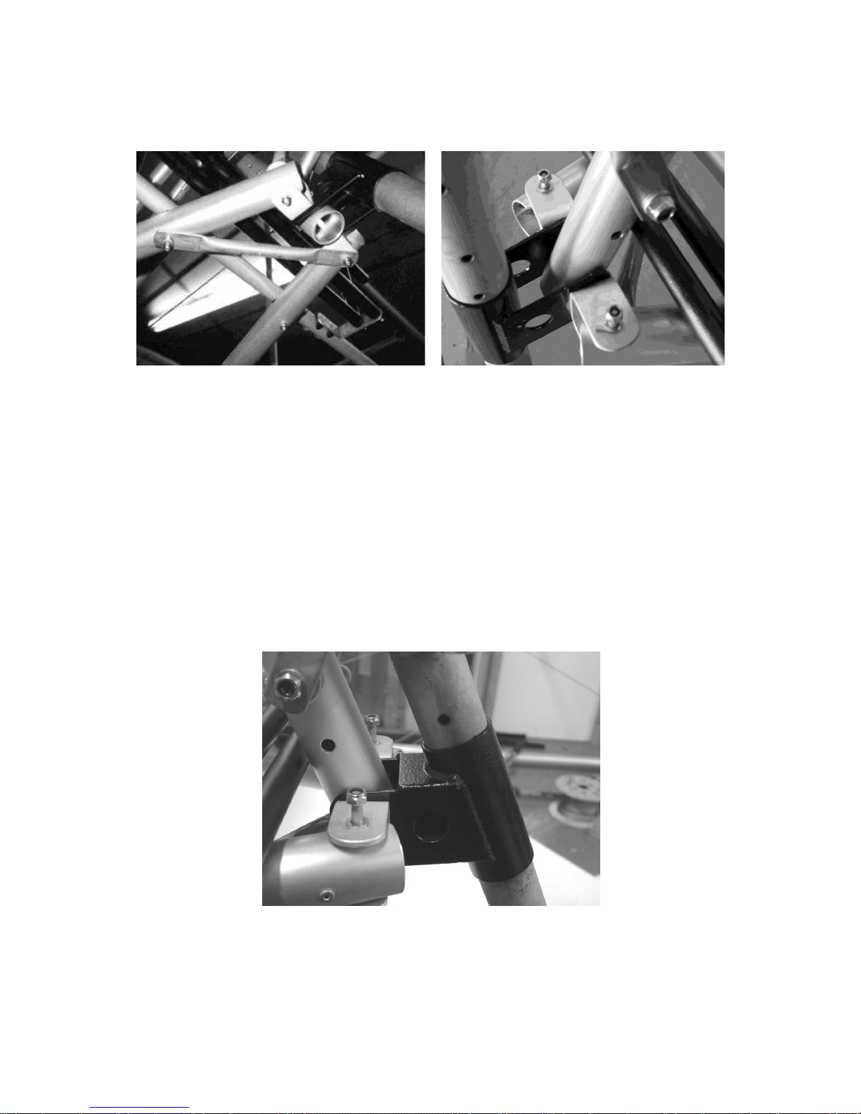
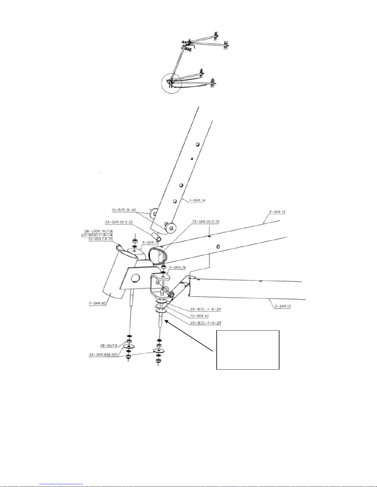
2.3.3 Fitting the front vertical to the lower cabin triangle.
Figure 19 forward ends of the lower cabin triangle viewed from below and above. Note non-
UKMOD nose leg lower guide.
a) Fix the lower guide SKR90 for the nose-leg to the lower part of the front
vertical tu14, between the two U-brackets SKR76.
Note these U-brackets are slightly different from those used elsewhere
in the kit, with the holes on the side parts further from the end (16mm
from the end to the hole centre).
The front vertical tu14 has a row of three 6mm holes at its upper end
(amongst others), and a row of three 8mm holes at the lower end.
UKMOD: a spacer tube is used on the U-bracket and nose leg guide
securing bolt as it passes through the front vertical tu14.
UKMOD: The guide SKR90 has additional webs welded onto it top and
bottom, Figure 20
Figure 20 UKMOD nose leg lower guide.
Page 28
28
Nynja Build Manual 1.4d
Figure 21 forward end of lower cabin triangle.
Note: Stud shown
may also be
supplied as a bolt,
and should be fitted
head up.
Page 29

29
Nynja Build Manual 1.4d
b) Apply threadlock to the bolt securing guide SKR90 to the front vertical tu14
and tighten firmly, but take care not to distort or crush the tube.
This should be done at this stage as the bolt holding this bracket is not
easily accessible later.
Whilst the spacer should prevent crushing of the tube, it is better not to
rely on it. It is permissible for the spacer to remain slightly loose, as
under load it will still prevent excessive deformation of the tube.
Do not distort the tube.
c) Mount the U-brackets SKR76 to the lower cabin triangle tubes SKR12
Note the use of a spacer sleeve in the tubes.
The studs should be long end downwards to mount the bottom of the
firewall and the front of the fuselage covering later.Discard the curved
metal washer if fitted – as this is a Skyranger part not used for the
Nynja.
If the bolt thread sticking out of the nut securing the U brackets to the
TU14 fouls the TU12 end file the end of the TU12 to provide clearance
d) Mount the steel diagonal-brace SKR43 to the bottom of the stud through the
port tube. Use thin plastic washers W.FL-1-6-24 and steel washers
SKR456.001
The other end of the brace will be attached to the rudder pedal mounts
later. The brace may be supplied attached to the mounts, have a look
under the packaging.
Thin plastic washers may be used to take up any slack between the
tubes and U-brackets.
Page 30
30
Nynja Build Manual 1.4d
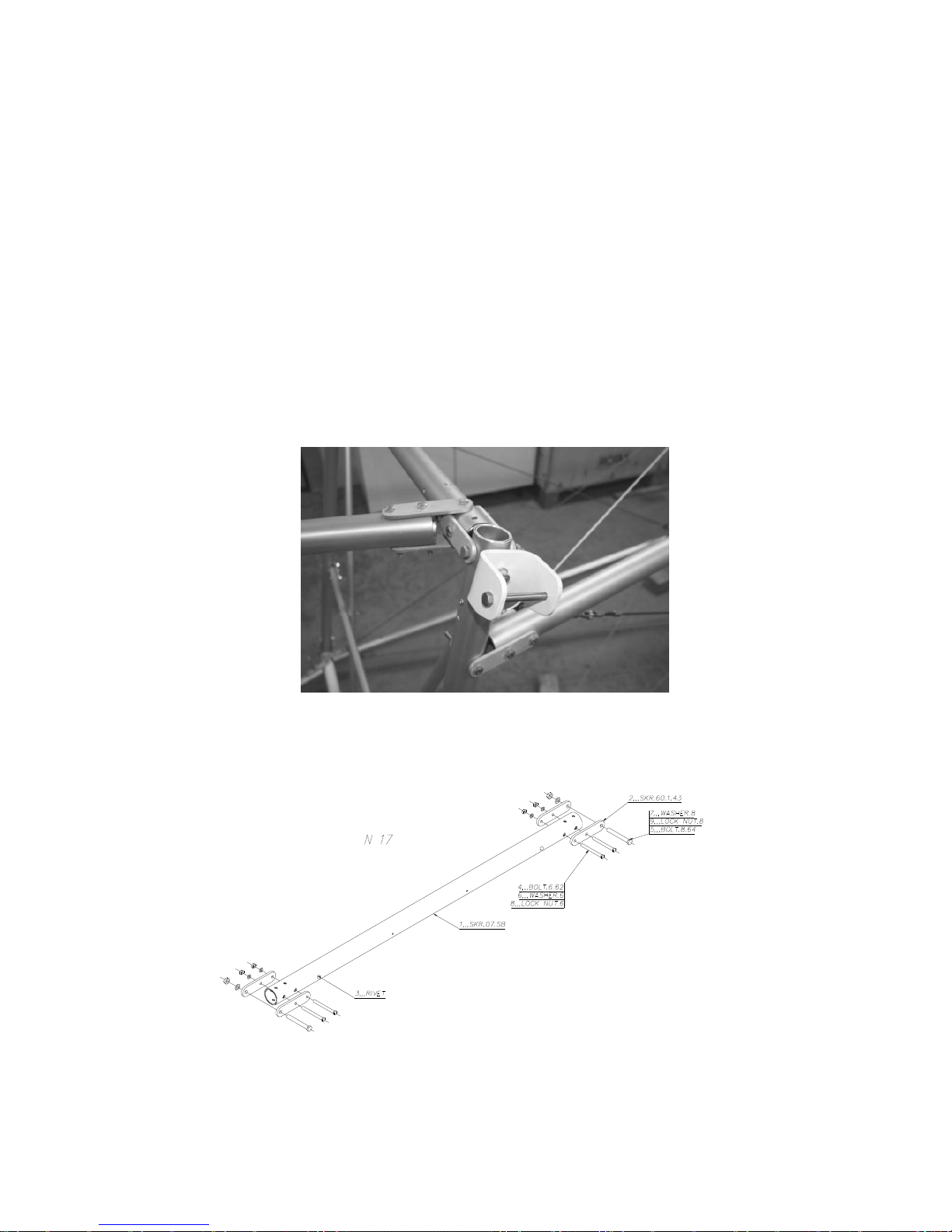
2.4 Upper Cabin Triangle
2.4.1 Fitting the sides of the upper cabin triangle to the upper rear cabin
cross-piece.
Refer to Figure 23 and 24.
a) Fix the aluminium linking-plates SKR60 on the upper rear cabin cross-piece
tube tu7, which links the trailing-edges of the wing.
These linking plates are drilled at one end with an 8mm hole and at the
other with two 6mm holes.
The row of small holes should point forwards, whilst the bolts point
rearwards.
The bolts will be tilted down and backwards compared to the vertical
bolt holes for the cabin upper triangle and tail cone tubes, as the rear
cabin frame is raked backwards.
Figure 22 Port end of the upper rear cabin cross-piece.
Figure 23 upper rear cabin cross-piece.
Page 31

31
Nynja Build Manual 1.4d
b) Assemble the upper cabin triangle tubes tu10 with aluminium linking-plates to
the upper rear cabin cross-piece tu7.
The drawing shows the lower cabin triangle tubes tu12, however the
fittings are the same on the upper cabin triangle tubes tu10. Note that
the tubes themselves are not the same.
The cut-outs at the front of the upper cabin triangle tubes tu10 should
face outwards.
Figure 24 rear of upper cabin triangle tube tu10.
2.4.2 Assembling the top of the front vertical tube.
a) Fix the U-bracket SKR75 and the pair of U-brackets SKR78 for the leading-
edges on the front vertical tube SKR14.
b) Mount the aileron cable pulleys.
c) Assemble the two upper cabin triangle tubes SKR10, linking them to the
double U-bracket SKR75.
Page 32

32
Nynja Build Manual 1.4d
8,,,SKR.94.SB
24,,,WASHER.8
30,,,CASTLENUT.8
31,,,SAFETY PIN
8,,,SKR.94.SB
24,,,WASHER.8
30,,,CASTLENUT.8
31,,,SAFETY PIN
Figure 25 forward end of upper cabin triangle.
Figure 26 forward end of upper cabin triangle.
Page 33

33
Nynja Build Manual 1.4d
2.5 Rear Cabin Frame
2.5.1 Preparing the rear cabin uprights.
Figure 27 rear cabin uprights and correct handing for attachment of SKR2 fuselage longerons
a) Fix the steel U-brackets for the trailing-edges with the taper downwards, using
an aluminium saddle washer under each, against the rear cabin uprights
SKR6.
The rear cabin uprights SKR6 have inner sleeves at their upper end,
and are handed in that the holes that connect the upper rear fuselage
longerons TU2 should be angled for the tailcone taper.
The nuts may foul the upper rear cabin cross-piece SKR7, in this case
file away a little from the TU7 to provide clearance.
A spacer should be used on the bolt inside the tube.
Page 34

34
Nynja Build Manual 1.4d
b) Apply threadlock and tighten the bolts holding the trailing edge U-brackets, as
they are not easily accessible later, but not so tight as to prevent easy rotation
of the fittings by hand pressure.
2.5.2 Fitting the rear cabin uprights.
Refer to figure 27
a) Assemble the rear cabin uprights SKR6 to the main undercarriage cross-beam
SKR9, using the second set of holes from the end.
Remember the bolt spacers on the two bolts at the bottom of SKR6.
The bolts should all point rearwards through the main undercarriage
cross-beam SKR6.
b) Lift the upper triangle into position on the rear cabin uprights SKR6 and
temporarily secure with an 8mm diameter bolt.
c) Secure the bolts through the rear cabin uprights SKR6 and the upper cabin
triangle tubes SKR10 including the proper spacers etc..
This is easier now the upper cabin triangle is in place, although it is still
worth leaving all the accessible bolts loose until more of the fuselage is
assembled.
The 8mm bolts securing the rear cabin uprights SKR6 are fitted with
spacers and the nut must not be done up yet as there are more pieces
to fit to it.
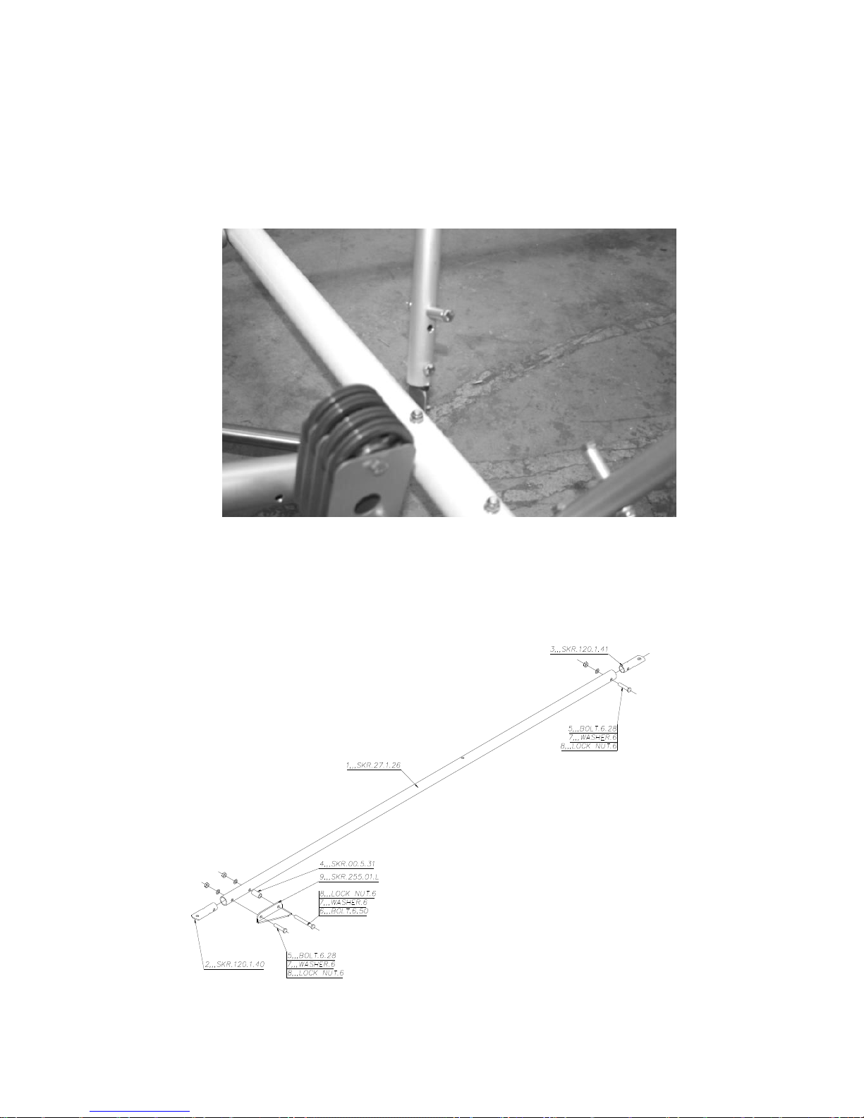
2.6 Rear cabin frame bracing.
Figure 28 lower and upper ends of rear cabin frame diagonals.
a) Bolts and fittings for the SKR9 tube are packaged separately – in a bag
marked ‘9’, Find these now.
b) Assemble the steel end pieces into the rear cabin frame diagonals SKR27.
The one with the 8mm hole goes at the upper end and the one with the
6mm hole goes at the lower end.
Page 35
35
Nynja Build Manual 1.4d
c) Install the bolt and spacer to support the seat a short distance above the lower
ends of the rear cabin frame diagonals SKR27, Figure 29
These should be oriented with the supporting part towards the middle of
the aircraft. Note that the spacer tube is also shown on Figure 30 as
well as the small bracket piece. The Nynja should be supplied with
round peg support as per picture below.
Figure 29 seat support peg.
d) Stiffen the cabin back with the two rear cabin frame diagonals SKR27 .
These are positioned behind the rear cabin uprights SKR6, with the
seat supports pointing inwards and upwards, and their supporting part
towards the front.
Figure 30 rear cabin frame diagonal, port side viewed from rear.
Page 36

36
Nynja Build Manual 1.4d
Figure 31, tu40, rear cabin frame cross-piece, looking from the front.
e) Fit the upper ends to the end of the 8mm bolts at the top of the rear cabin
uprights SKR6.
The upper end of the round tube part of SKR27 will touch the rear cabin
uprights SKR6. If interference appears great, it is permissible to flatten
or file the upper ends of the SKR27 to ease this. A steel washer may be
placed under the steel end piece on the rear cabin frame diagonals
SKR27, to further help, but don’t be concerned at some interference.
Attach the lower ends to the rear of the main undercarriage cross-beam SKR9.
The final attachment be quite tight to get on and an additional person or
a ratchet strap may be necessary to provide tension to the frame to
help.
Assemble the rear cabin frame cross-tube SKR40 and attach to the rear of the rear
cabin uprights SKR6, but in front of the rear cabin frame diagonals SKR27.
The bolts should point rearwards, and pass through the upper ends of
the stainless braces SKR144 before the rear cabin uprights SKR6 and
finally the attachment plate on the rear cabin frame cross-tube SKR40.
Include a thin plastic washer between the brace and the aluminium rear
cabin uprights.
2.6.1 Fuel tank upper mounting pieces.
Refer to Figure 32
Page 37

37
Nynja Build Manual 1.4d
a) Where the rear cabin frame cross-tube SKR40 crosses the rear cabin frame
diagonals SKR27 they should be connected with a bolt, pointing backwards.
UK MOD – the holes will need drilling out to 6mm. Suitable 6mm bolts
are included with the wooden spreader bar pieces.
b) Paint the wooden tank spreader pieces with fuel-proof paint.
Fuel proof paint is available from model aircraft shops, an enjoyable but
potentially expensive visit!
c) Assemble the wooden fuel tank load spreading pieces on the rear end of
these bolts and tighten, but do not crush the wood excessively.
Ensure that the end of the bolt is below the level of the rear surface of
the wooden pieces. Long side faces outwards
Figure 32 fuel tank wooden tank spreader pieces.
2.7 Engine Supports
2.7.1 Rotax 912.
Figure 33 Rotax 912 engine mounts
Page 38

38
Nynja Build Manual 1.4d
Figure34 Rotax 912 mounting bracket – note position of TU310 is reversed for Nynja – as
shown correctly below
Fig 35 Nynja engine mount assembly
Remove
this washer
Page 39

39
Nynja Build Manual 1.4d
Fig 36 Nynja firewall support brackets, should be fitted on the engine mount bolts at the front
of the SKR19’s at this stage as shown (normally found packaged with firewall)
Fig37 liaison of TU19’s, TU14 and SKR8
a) Locate the two central cabin tubes SKR19 onto the front vertical SKR14
including the steel engine mounting bracket 98 between them. Loosely bolt in
place using the washers and saddle washers.
Aluminium washers – Note
that TU14 is a different
diameter – make sure the
correct saddle washers are
used!
7mm and 1mm plastic
washers
Page 40

40
Nynja Build Manual 1.4d
Fig 38 Rear of SKR19 – ends must be bent to align like his
b) It is worth trial fitting the central cabin tubes to the underside of the main
undercarriage cross-beam to allow the stainless steel brackets to be bent in a
vice to align properly, Fig 38
Before fitting the SKR98 steel engine mount it saves time later if you
drill a 6mm hole near the front to fit an earth connection, picture in
wiring section of manual Figure 236
The two plastic rings which form the aileron stops may be slid over the
tubes at this stage (see the section on the ailerons in the Wing
chapter), although they may require removal later by cutting them off if
adjustment of the aileron movement is required.
c) Attach the two central cabin tubes SKR19 onto the main undercarriage cross-
beam SKR9.
Remove the pulley set from the assembly and put to one side for now.
This makes fitting the TU19’s to the undercarriage cross beam much
easier. But leave the long bolt (stud) in position through the two tubes, which will help ensure alignment and prevent possible difficulty fitting
later.
Note the bolts through SKR9 should point upwards, and should pass
through the stainless-steel under-seat diagonal tubes SKR42 before
passing through the central cabin tubes SKR19 and the main
undercarriage cross-beam SKR9.
The steel end pieces on the central cabin tubes SKR19 may require
bending slightly to allow them to sit flat against the underside of the
main undercarriage cross-beam SKR9.
d) Loosely fix the two stainless-steel upper triangulation tubes SKR24 to the top
of the front vertical SKR14, including saddle washers.
Page 41

41
Nynja Build Manual 1.4d
e) Loosely attach the upper and lower stainless-steel triangulation tubesSKR23
to the central cabin tubes and the engine mounting brackets, including the
alloy side pieces 298, Figure 35 and Figure 39.
It will be necessary to tweak the ends of the steel triangulation tubes to
position them flat against the engine mount and the front vertical tube
SKR14.
UKMOD: the front pair of mounting bolts should have a spacer tube
fitted as they pass through the two central cabin tubes SKR19. This
allows them to be done up reasonably tight, without ovaling the tubes.
This should result in thread protruding from the Nylocs.
If no thread is showing, the washers shown under the nuts may be
omitted (washers under bolt heads should have been removed earlier)
Check the alignment of the stainless-steel parts, and tweak as
necessary to get them to all lie flat against each other. This will reduce
the space they occupy along the bolts.
Note the presence of the steel diagonal brace SKR310 on the
starboard side, and a corresponding additional thick plastic washer on
the port side to assure symmetry between sides.
Note that the 298 plates are handed and the starboard one has a
recess machined in, as shown below.
Fig 39 handing the 298 plates
Note recessed section
on starboard 298 plate
only
Page 42

42
Nynja Build Manual 1.4d
Fig 40 Forward end of SKR19 and Liaison of engine mount plates 298BK, SKR310, upper
triangulation tubes SKR24’s and lower triangulation tubes SKR23. Note arrangement of plastic
washers – only fit them where shown.
Figure 41 upper engine mount triangulation tubes.
1mm plastic washer
TU24
TU23
TU310
3mm plastic washer
Page 43

43
Nynja Build Manual 1.4d
Figure 42 lower engine mount triangulation tubes.
f) Leave the bolt holding SKR310 slack enough to rotate it out of the way when
fitting the engine.
Figure 43 lower triangulation tubes TU23 and lower engine mounts
g) Loosely fix the two stainless-steel lower triangulation tubes SKR23 to the front
vertical tube SKR14, including saddle washers, Figure 42 and 43.
Page 44

44
Nynja Build Manual 1.4d
It may be necessary to apply some weight to the engine mount to fit the
bolt holding the lower triangulation tubes SKR23 to the front vertical
tube, or to use a twisted rope as shown in figure 44.
Figure 44 twisted rope used to pull down on engine mount.
h) The bolts around the engine mount may now be tightened, starting with those
on the mount itself before tightening the bolts holding the top and bottom ends
of the triangulation tubes.
Leave the bolt holding SKR310 loose enough to turn it.
i) Check engine mount plates spacing:
the distance between the plates should be 175-180mm, measured at
the front set of holes where the rubber engine mounts fit. It may be
necessary to adjust the spacer size under the rear bolts that hold the
plates in position adding or subtracting 1or3mm plastic washers, to get
this measurement.
Figure 45 Rotax 912 engine mounts, front view.
175-180mm
Page 45

45
Nynja Build Manual 1.4d
j) With this measurement verified, the diagonal brace SKR310 can be bent to fit
in position and sit flat against the port engine plate. The plate can then be
drilled and the SKR310 fixed into position with a 6mm bolt.
The SKR310 upper edge should be approximately 0-5mm from the upper
edge of the engine mounting plate.
Check that the distance between the plates has not changed during this
process.
Figure 46 fixing position for TU310
k) The lower engine mounts, Figure 43 and 47, should be attached to the front
vertical SKR14.
Figure 47 Rotax 912 lower engine mounts.
0-5mm
Page 46

46
Nynja Build Manual 1.4d
2.8 Floor
a) The floor is supplied pre made out of composite. The grey side is the upper
side. It may be surfaced with vinyl or carpet, or left as is.
Cut a hole in the floor for the battery box:
The hole is located on the centreline, approximately 1cm back from the
rudder pedal mounting bar SKR18. The hole is 15cm long by 9cm wide.
Figure 48 battery location.
Figure 49 view of installed floor.
Page 47

47
Nynja Build Manual 1.4d
b) Slide the floor in before fitting the SKR15 but first:
Apply some of the supplied thin 2x10mm self-adhesive foam in strips along
the tops of the tubes which the floor rests on, to prevent it rattling.
c) Fit the seat front support tube SKR15, above the lower cabin triangle tubes
SKR12 with a pair of saddle washers per bolt between the two tubes.
Note the tapered ends of the tube taper towards the front.
Figure 50 TU15 assembly
d) The forward ends of the steel under-seat diagonal tubes SKR42, which were
attached to the main undercarriage cross-beam, should be attached to the
bottom of the bolts securing the seat front support tube SKR15 to the lower
cabin triangle tubes SKR12 with a thin plastic washer or saddle washer
between the steel tube and the aluminium tube.
Figure 51 SKR15 seat front support tube.
Page 48

48
Nynja Build Manual 1.4d
e) The floor should be slid back against the front of the seat front support tube
SKR15.
It should butt up against the underside curve of the tube, but not
actually pass beneath it, thus preventing the floor from lifting upwards
along its rear edge in negative-g situations.
Mark through from the bottom the positions of the holes for the rudder
pedal mounting bar, and drill the floor to suit.
The floor passes beneath the rudder pedal mounting bar.
f) To further stiffen the floor in the middle of the cockpit, fit the small piece of L-
section aluminium to support the floor, see Figure 56.
This is attached by the bolts which hold the central bracing pieces,
which are fitted later.
g) Install the battery box, and secure it with four bolts with penny washers.
h) Fit the webbing strap, passing right around the box through the slots in the
side of the box, with the buckle at the top.
Leave fitting the battery until later.
2.9 Rudder Pedals
Refer to figure 52.
a) Fit the rudder pedals orientated as shown on the drawing, before attaching the
second of the two L-brackets if they are not already in place.
b) Fit the rudder pedal mounting bar SKR18 to the top of the lower cabin triangle
tubes SKR12, over the top of the floor.
c) Make sure that there are saddle washers between the pedal bar and the floor
but NOT between the floor and the lower cabin tubes – this may mean
removing a set from the assembly
Figure 52 rudder pedals.
Page 49

49
Nynja Build Manual 1.4d
d) Attach the rear end of the steel diagonal-brace SKR43 to the bottom of one of
the bolts, including a plastic washer between the steel brace and the
aluminium tube.
e) If no floor is fitted, put pieces of prop-tape on the lower cabin triangle tubes
SKR12 beneath the rudder pedals to protect the tubes from abrasion from the
pedals when under load.
f) Cut off any protruding ends of the rudder pedal mounting bar bolts beneath
the aircraft, to prevent them rubbing on the coverings. Nut caps may also be
fitted.
2.10 Control Stick Assembly
Figure 53 control stick and torque-tube parts
Page 50

50
Nynja Build Manual 1.4d
a) If not already done, attach the aileron horn to the machined ‘top hat’ with 4mm
bolts.
Rivets must not be used here, as the fitting carries all the tension loads
from the elevator controls. Use the bolts supplied, do not use any
unknown strength bolts. Attach the top hat to the front vertical SKR14
by the pivot bolt through the aileron horn, inserted from the rear.
The pivot bolt must be assembled in the following order:
Bolt head
Large metal washer
Plastic washer
Aileron horn
Rubber grommet
Plastic saddle washer
Front vertical SKR14
Plastic saddle washer
Large metal washer
Small metal washer if necessary for spacing)
Castle nut and split pin
b) When all is in final position, this should be done up tight enough to remove
excess play but without discernible friction.
c) Fit the stick to the stick pivot fork with thin nylon washers either side of the
stick in the stick pivot fork.
d) The pivot bolt should be done up just tight enough to remove any play but
allow movement of the stick without discernible friction.
e) Rubber rings are is supplied to act as elevator stops. They should be
positioned on the stick so as to engage on the edge of the fork jaws,
They may be secured by glue and/or cable ties above and below them.
f) Fit the plastic torque-tube bearing into the rear pivot support.
The bearing is inserted from the front. Then if the forward pivot bolt were to
fail, the stick would still be held in place by this bearing.
Figure 54 torque-tube bearing.
Page 51

51
Nynja Build Manual 1.4d
g) The stick pivot fork end should be fitted through the plastic torque-tube
bearing and into the torque-tube.
Note that the plastic bearing fits over the fork end and is trapped in
position by the torque-tube. This should be an easy fit with 0.5mm free
play along the axis of the torque-tube. If this is tight it may be necessary
to file the end of the torque-tube a little to prevent binding.
If the bearing is tight on the stick pivot piece when positioned correctly,
the bearing should be abraded lightly until a smooth action is achieved.
h) The torque-tube can now be fitted onto the front pivot (attached to the aileron
horn), and the rear pivot can be bolted to the central cabin tubes SKR19.
Note that the rudder stop cables will be fitted between the rear pivot
support and the central cabin tubes, do not tighten these bolts up
without the stops in place.
It may be necessary to slot the holes horizontally in the rear pivot where
it attaches to the central cabin tubes SKR19 to allow it to take up the
exact alignment of the torque-tube, but note the rudder stop cables will
have some effect on this alignment.
i) Insert and secure the bolts holding the fittings into the ends of the torque-tube.
Page 52

52
Nynja Build Manual 1.4d
2.11 Finishing the Forward Fuselage
2.11.1 Tightening bolts
At this stage it is permissible to tighten most of the bolts, as the cabin frame now
forms a well braced structure. The exceptions are the bolts securing the lower ends
of the rear verticals to the main undercarriage cross-beam, as these will be undone
when fitting the undercarriage.
Check the basic alignment of the structure as you tighten the bolts, trying not to work
in such a fashion as to introduce any unnecessary distortions into the structure (e.g.
don’t do all the bolts up along one side and then along the other).
Some slight misalignment is inevitable in a pre-drilled structure of this type, and
unless this is severe it is probably best to live with it rather than to open out too many
bolt holes. A slightly asymmetrical but well defined shape is preferable to a perfectly
aligned shape with sloppy bolts.
Remember to apply threadlock, and do not over tighten the bolts. The tubes should
not be visibly distorted. Remember the bolts are not relying on their tightness to stay
done-up, they only need to be tight enough to avoid the parts rattling against each
other. The Nyloc and the Loctite are responsible for keeping the bolts done-up.
2.11.2 Central brace
a) Fit the aluminium angles 2 and 3 linking the central cabin tubes SKR19 to the
seat front support tube SKR15.
These are not pre-drilled, as the exact hole positions are affected by
the general alignment of the rest of the fuselage.
b) Bolt the angles to the seat front support tube SKR15 first, then drill them to
match the holes in the central cabin tubes SKR19.
To aid clearance for the rudder and elevator cables, it is recommended
that (if supplied) both the lower saddle washers on the seat front
support tube SKR15 are omitted. This leaves only the side ones
against the central cabin tubes SKR19.
An additional thin plastic washer may be fitted between the central
brace and the starboard central cabin tube to increase clearance for the
rudder cable.
The bolts should pass from the middle towards the outside, to clear the
elevator cables.
Page 53

53
Nynja Build Manual 1.4d
Figure 55 central bracing pieces. Note the bolts should be the other way around (as shown in
photo fig 56).
Figure 56 central bracing pieces.
Page 54

54
Nynja Build Manual 1.4d
3 Rear Fuselage
The rear fuselage is composed of four longitudinal tubes, connected by the vertical
fin at the tail end and braced by a single frame half way down. Steel cables are used
diagonally to stiffen the structure, with tension applied by turnbuckles fitted to two of
the cables.
Once again, do not tighten the nuts until the assembly has been completed.
3.1 Tail End
a) Fit the rudder post (the trailing edge of the vertical fin) between the two pairs
of saddle washers shown in Figure 57,58, 59.
Do not forget the steel T-piece to which the horizontal stabiliser halves
attach, and the extra flat washer on the lower bolt,
Some difficulty may be encountered with access to the various nuts in
this area. A useful trick to hold a nut to the end of a spanner is a piece
of sticky tape placed over the end of the spanner.
Tighten these particular nuts now using Loctite, as they are very difficult
to reach later.
b) Fit the stainless-steel bracket in front of the rudder post, and attach the upper
pair of longitudinal tubes SKR2.
Figure 57 vertical fin and horizontal stabiliser rear mountings.
c) Attach the bottom end of the vertical fin to the bracket and longitudinal tubes
SKR4 in a similar manner Figure 58.
If you do not have suitable supports or a helper to hold the front ends of
the tubes at this stage it can be helpful to mount the bracing frame (as
detailed below) to the lower pair of longitudinal tubes, followed by
Page 55

55
Nynja Build Manual 1.4d
resting the upper pair of tubes on it whilst they are attached to the
bracing frame and the rudder post is attached to the lower pair of tubes.
Figure 58 rear end of upper rear fuselage tubes.
Figure 59 rear end of lower rear fuselage tubes.
Page 56

56
Nynja Build Manual 1.4d
3.2 Bracing Frame
a) Fit the rear fuselage bracing frame SKR39 to the upper and lower rear
fuselage tubes using the holes approximately mid-way down the tubes.
b) Check the orientation of this frame against the drawing below, as examples
have been delivered assembled the wrong way around.
Figure 60 rear fuselage bracing frame. Note orientation arrow.
b) Attach the Upper and lower bracing cables A and B to the central frame at this
point. – see section 3.4 for details
Page 57

57
Nynja Build Manual 1.4d
3.3 Front End
a) Prepare the front ends of the lower tubes.
b) Prepare the front ends of the upper tubes.
Figure 61 forward end of lower rear fuselage tubes Note upper tubes have brackets orientated
at 90 degrees from that shown and cables are arranged differently on Nynja. See Figure(s) 62
c) Mount the front ends of the upper tubes onto the SKR6 tubes as shown below.
Figure 62 forward ends of upper and lower tubes
d) Attach the lower tubes to the main undercarriage cross-beam.
6-SKR.00.5.37
SKR.131
Page 58

58
Nynja Build Manual 1.4d
3.4 Fuselage bracing cables
Figure 63 fuselage cable arrangement overview
a) If necessary Identify the cables from the following table:
Cable Number
and thickness
length
Tangs
Cable A 2mm
1407
Forward bent, rear
straight
Cable B 2mm
1578
Both straight
Cable C 3.6mm
1262
Both straight
Cable D 3.6mm
1647
Forward bent, rear straight
Cable E 3.6mm
1472
Both bent
Cable F 3.6mm
1645
Both bent
Lengths taken from tang hole centers. Cable C is made up with a turnbuckle at the
forward end and a tang. Length taken is total length from tang end hole centers with
turnbuckle fully closed
Side view
Plan view
Cable C
Cable D
Cable E
Cable F
Upper cables A
Lower cables B
Page 59

59
Nynja Build Manual 1.4d
C cable tang under
A cable tang
E cable tang over
D cable tang
C cable tang under
F cable tang
Figure 64 fuselage cable ends detail
Note both pairs
of rear cables
cross at rearmost
attachment point
Page 60

60
Nynja Build Manual 1.4d
Figures 65 cable arrangement further overview
Page 61
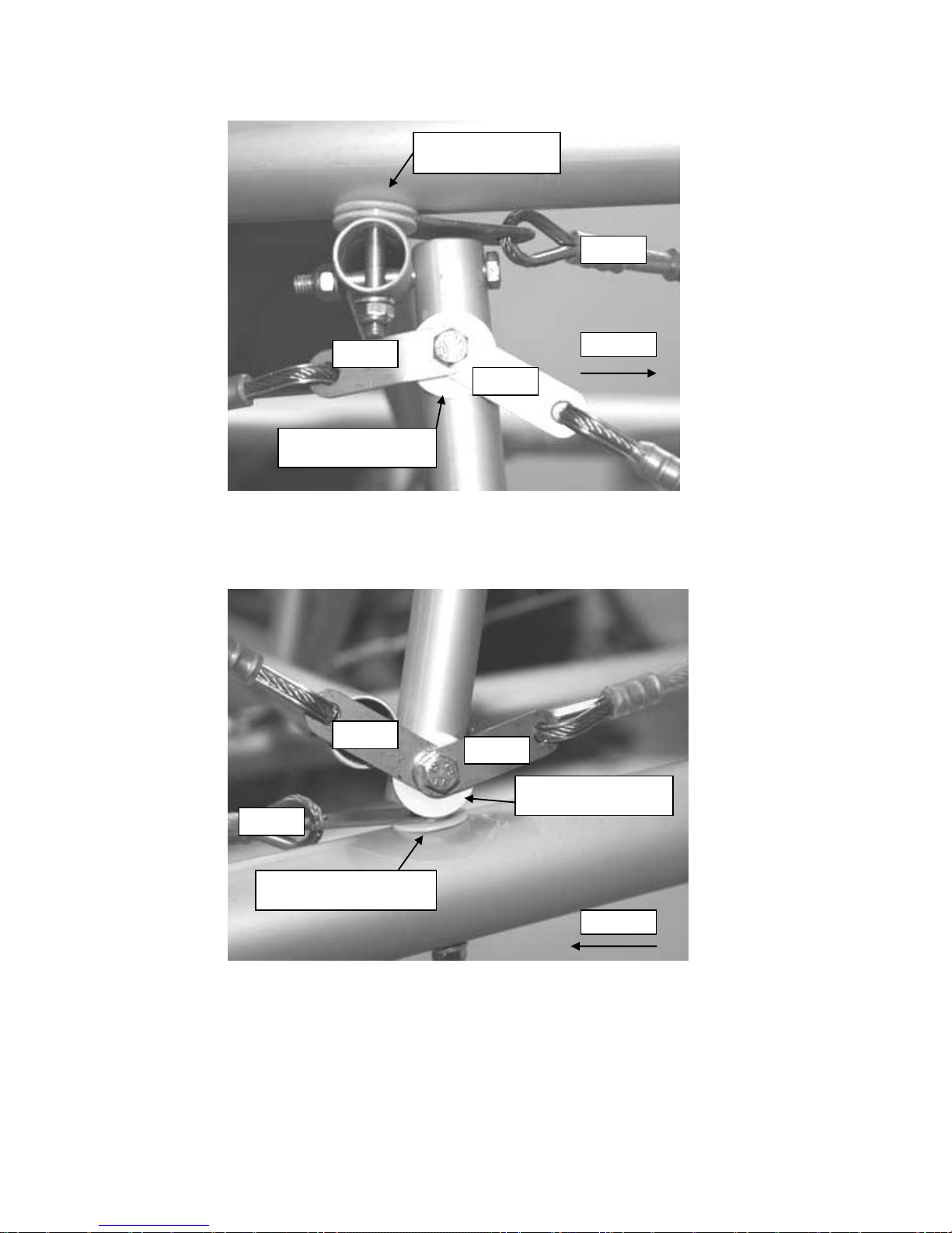
61
Nynja Build Manual 1.4d
Figure 66 cable arrangement Upper starboard side of central frame
Figure 67 cable arrangement lower port side of central frame
Forwards
Forwards
A cable
E cable
D cable
F cable
C cable
B cable
1mm plastic washers
above and below tang
3mm plastic washer
between tangs and tube
1mm plastic washer
between tangs and tube
1mm plastic washer between
tang and tube only
Page 62

62
Nynja Build Manual 1.4d
b) Loosely fit all cables in the positions shown, and with tangs overlapped as
shown above. Note tangs may have multiple holes. Only attach through the
very end ones!
c) Forward side bracing C cables.
These are the only cables with turnbuckles. Tensioning the turnbuckles
sets the tension in D cables also, and permits adjustment of Fin angle.
d) The tension in the rear cables E and F is provided by attachment at rear. Fit
first on very end of bolt with nut only just engaged.
The rear of the fuselage can be lifted which will aid attachment of E
cables at front position. Fuselage rear can be pushed down to aid
attachment of F cables at front position. Twisting the cable in the
direction of the cable layup can be used to shorten the cables if
necessary. The aim is to eliminate all slack at this stage as much as
possible and it still be possible to attach them. Final tensioning of these
E and F cables is achieved by tightening the rear attachment nuts.
e) Upper bracing cables A. Should first be fixed at the rear.
The wires should be twisted as necessary to eliminate slack to make
the cable a tight fit on the start of the forwards fixing bolt. Final
tensioning is achieved as the forwards fixing nuts are tightened.
f) Lower bracing cables B should be fixed at the rear first.
They should be twisted to provide tension and fixed at the front
Inserting the bolts at an angle initially and levering straight to tension
the cable as they are fully inserted. Take care not to lose the spacer in
the tube – use another bolt or thin screwdriver inserted at the top to
hold spacer in position and bolt is withdrawn and reinserted.
g) Apply light tension to the cables but do not tighten at this time.
Page 63

63
Nynja Build Manual 1.4d
3.5 Tailplane Front Mounting
a) Attach the aluminium corner section SKR22, figure 68, to the upper rear
fuselage tubes SKR2.
b) Test fit the tailplane halves between this front mount and the rear mounts.
There should be a thin plastic washer or saddle washer at the rear, and
a small saddle washer at the front. If the bolt head at the front of the
tailplane contacts the front mount, an additional plastic washer may be
used.
The SKR22 nay be supplied with slotted mounting holes. This is so it
can be adjusted slightly fore and aft for the tailplane fit.
Figure 68 vertical and horizontal stabiliser front mounting.
Page 64

64
Nynja Build Manual 1.4d
3.6 Fuel Tank Support and Flap Handle
Figure 69 fuel tank support / flap handle mount.
a) Fit the fuel tank support SKR20 to the lower rear fuselage tubes SKR4, with
the U-bracket located towards the port side of the fuselage and facing
upwards, Figure 69 and 70.
Figure 70 flap handle and fuel tank support bar.
Page 65

65
Nynja Build Manual 1.4d
b) Fit the flap handle to the U-bracket, biasing the flap handle tube as far to the
starboard side of the bracket as possible, leaving only one saddle washer
between the handle and the starboard side of the bracket, figure 71.
Figure 71 flap handle pivot.
Do not space the detent lever away from the handle, use only one thin
plastic washer or a single saddle washer between them. It is
permissible to bend the lever slightly into a Z-shape to make it align
with the flap handle and the latching slot.
Figure 72 flap lever detail
c) Fit the S70 spring from the flap handle to the detent lever, in position shown
in figure 72. The eye end may need opening up slightly to fit in the rear hole
Spring fits here
Page 66

66
Nynja Build Manual 1.4d
Figure 73 Flap handle
Not Tightening the Bolts and cables!
Do not finally tighten the bolts or cables around the rear fuselage at this stage – this
will be detailed later after the landing gear is attached.
Page 67

67
Nynja Build Manual 1.4d
4 Undercarriage
4.1 Wheels
All three wheels and tyres are identical, only the hubs differ between the nose wheel
and the main wheels, which are fitted with brake discs.
Figure 74 wheel parts.
a) Place an inner tube inside a tyre, Figure 75.
b) Loosely place the tyre onto a wheel half with valve hole, locating the valve
through the hole in the wheel half.
Figure 75 tyre and inner tube.
c) Place the other wheel halve onto the first wheel half, so that the tyre and inner
tube are positioned between the two wheel halves.
d) Take a hub, put a drop of thread lock into each of the six threaded holes, and
position it against the wheel half opposite the valve side, Figure 76. Note that
the hub has a machined face with square inside corners one side and a
radiused face the other. The machined face should sit against the wheel
halves. Do not assemble with hub between wheel halves!
Page 68

68
Nynja Build Manual 1.4d
e) Check that the inner tube is not trapped between the wheel halves, and pass
all six bolts from the valve side through their washers, both wheel halves, and
into the threaded holes on the hub.
f) Tighten the bolts and inflate the tyre to 26psi. If the tyre does not slip easily
into position a little squirt of neat washing up liquid around the rim can be used
to make it slip more easily.
Figure 76 placing a hub against the wheel halves.
Figure 77 a wheel minus the tyre.
Page 69

69
Nynja Build Manual 1.4d
4.2 Main Undercarriage
4.2.1 Brake calliper attachments
a) Check that the callipers are bolted together by the correct bolt to leave the
other two holes free to mount the calliper offset slightly to the rear of the
undercarriage legs. See Figure 88 for the manner in which the callipers are
intended to be mounted.
It will probably be necessary to swap the bolt holding the one of the
callipers together to the other hole. This will result in a handed pair of
callipers.
b) If not already done, drill an 8mm diameter hole in each undercarriage leg
18mm above the upper rear stub axle mounting holes, as shown in Figure 78.
Mark carefully, and recheck before drilling. Use a small pilot drill
first, and recheck its position. Then drill out to the proper size.
Try to drill squarely. It is permissible to allow a little slop in the hole size,
to allow the callipers to find their own alignment.
Take care to make a handed pair. The callipers and holes for them
are to the rear of the undercarriage legs, and at the narrow end of the
legs.
Figure 78 hole for brake calliper mounting.
Page 70

70
Nynja Build Manual 1.4d
4.2.2 Undercarriage legs
a) If spats are to be fitted, fit the mounting brackets on the lower pair of stub axle
mounting bolts on the wheel side of the stub-axle flange, figure 80.
Use the longer bolts supplied in the spat kit. Excess bolt threads can be
trimmed off. The bracket may need relieving with a file if there is
interference with the stub axle weld
b) Fit the brake mounting piece to the forward upper stub axle bolt, and tighten
the stub axle bolts.
Note if spats are fitted the stub axles should be attached with the outer
fixing bolt vertical – not horizontal as shown below.
Figure 79 Nynja undercarrige leg
Page 71

71
Nynja Build Manual 1.4d
Figure 80 main gear inner spat mount.
c) Fit the undercarriage legs to the main undercarriage cross-beam SKR9
Make sure that the legs are on the correct sides to place the brake
callipers towards the rear!
Figure 81 main gear leg mounting.
Steel drag braces
Page 72

72
Nynja Build Manual 1.4d
d) The outer clamp should be positioned as far outboard as possible, against or
close to the plates holding the base of the rear cabin uprights SKR6. Don’t
fully tighten yet.
Figure 82 outer U-clamp position.
e) Fit the steel drag braces (Fig 80), and then tighten all attachment bolts.
The forward end attaches under the SKR144 triangulation side tube (which
should be fitted at this time assemble as per Figure 80. Ensure the attachment
bolt does up tight without becoming thread-bound, It may be necessary to add
another washer under the nut to achieve this balance. Bolts should be fitted
head down as shown. Note the bolt that attached the SKR144 is longer than
the rear bolt – check they are correctly orientated so.
The lower rear end goes under the gear leg and the upper rear end goes over
the top of the upper clamping block. Ensure the front attachment bolt does up
tight without becoming thread-bound, but also has no thread bearing on the
drag brace. It may be necessary to adjust with washers under the nut to
achieve this balance.
Figure 83 rear and forward ends of starboard drag brace
8-40 saddle washer
3mm plastic washer
Metal washer under
bolt head and nut
Page 73

73
Nynja Build Manual 1.4d
Figure 84 interference cure
You may experience interference between the undercarriage leg and the bolt head
as shown. If so file a rebate in the undercarraige leg as required. Make sure edges
are smooth and protect the bare metal with some paint or laquer.
4.3 Nose Gear
Refer to Figure 85.
a) If no spats are to be fitted apply grease to the inside of the nose wheel lower
and upper guides. If spats are to be fitted, then leave this until the nose leg is
removed to fit the spat.
This is to minimise the risk of contaminating the rubber washers with
grease. It is best to leave fitting the spats until the end of the build,
otherwise they are likely to suffer damage during the rest of the build
(yes you will drop that hammer on it!).
b) Slide the nose leg up through the lower guide.
c) Put a large steel washer, then 7 rubber washers, then another large steel
washer, onto the nose leg before sliding it up through the upper mount.
Washers and axle parts may be packed separately marked ‘88’.
Check the number of rubber washers supplied, you may receive an
extra one or two. Use only the specified number.
It is important that the nose leg should be free to swivel in its guides
with little or no perceptible friction.
If the nose leg is stiff to turn due to a slight misalignment between the
upper and lower brackets try turning it around 180°.
If the nose leg still does not easily align with the upper bracket in a
side-to-side manner, slide it clear of the upper bracket and gently apply
a tweak to the lower mount using the nose leg itself as a lever. The aim
is to achieve good alignment to remove any friction in the rudder
controls. If a small tweak does not suffice, the holes securing the lower
guide may be elongated slightly, parallel with the nose leg. Do not
Page 74

74
Nynja Build Manual 1.4d
elongate them in any other direction, as this will introduce slop into the
position of the lower guide.
If the nose leg is still stiff to turn, smooth any protruding weld inside the
upper and lower mounts with abrasives. A small file or a flap wheel can
be useful.
Do not get oil or grease onto the rubber or metal washers, as this may
cause them to slip over each other in a very heavy landing. This can
result in the rudder control circuit feeling stiff or binding, due to
misalignment of the nose wheel steering bar.
Figure 85 nose leg
d) Above the upper mount there should be another two large steel washers with
one, two, or three rubber washers between them as required, secured by a
bolt though the nose-leg.
If a nice fit without excessive vertical play cannot be achieved, make a
sleeve to go over the top of the nose-leg, and drill it for the securing bolt
at the required position to hold the nose-leg firmly in place. Ensure that
the fitting is not squeezing the rubbers, as this will increase friction. A
little vertical play is no problem and better than an overly tight fit.
e) Ensure that the lower engine mount triangulation tubes passing either side of
the nose leg do not touch it.
Use additional washers to space out the lower ends of the triangulation
tubes if necessary.
Page 75

75
Nynja Build Manual 1.4d
4.3.1 Nose wheel
a) Assemble the wheel on its axle SKR101 with a spacer tube SKR102 on each
side figure 85.
The spacer tubes are cut to different lengths to centre the wheel on the
axle, as the wheel is not symmetrical about the hub.
b) The axle should be attached behind and below the forks.
Check that the tyre does not rub against the side of the forks. The fit
can be adjusted by filing the holes in the spacer tubes so that the wheel
can be moved sideways. Once in a perfect central fit, tightening the
attachment bolts will lock it into place.
4.3.2 Nose wheel steering
a) The nose leg fits to the steering bar between the two 90 degree brackets.
Figure 86 Nose wheel steering.
UKMOD, remove these washers
and change for rubber grommets
UKMOD Fit rubber grommets here
Page 76

76
Nynja Build Manual 1.4d
b) Temporarily fit the two small steel pushrods SKR44 and SKR45 linking the
steering bar to the rudder pedals. Use the middle holes at this stage.
One pushrod is longer than the other to account for the offset of the
rudder pedal pivot bars.
c) UKMOD: Rubber grommets must be fitted between the box section and
steering pushrods and between the pushrods and the pedals to facilitate angle
change at steering extremes.
Ensure that you have fitted these, as otherwise the steering will not
operate properly.
Make sure all the other metal and plastic washers are removed. Fit one
of the plastic washers supplied in the bag with the grommets under
each bolt head
Do not tighten the bolts so much that you completely squash the rubber
grommets!
d) Temporarily fit the pushrods to the rudder pedals, using the middle holes on
the pushrods and the second hole from the top of the pedals.
e) Pedals may be adjusted rearwards by using one or both of the outer holes in
the pushrod. However using the inner holes to move pedals forwards is not
recommended as it can cause fouling with the rudder stop cables which are
fitted later.
f) Note the bolts used at both ends of the pushrods should be fitted with split-
pins once adjustments are finalised.
Figure 87 nose wheel steering bar, with rubber grommets between pushrods and box section
and pushrods and rudder pedals, note the white plastic washers shown near the arrows should
not be fitted.
Page 77

77
Nynja Build Manual 1.4d
4.4 Brakes
4.4.1 Brake brackets
a) Slide the main wheels into place on the stub-axles. Use a smear of grease.
Sometimes the wheels are a tight fit on the stub axles. If the wheel
cannot be slid on and off easily use some fine glasspaper and smooth
the exterior of the stub axle, then assemble with a little grease.
b) Slide the callipers over the brake discs, Figure 89
The callipers must be handed to sit behind the undercarriage legs by
swapping the bolt which holds the calliper halves together to the other
hole on one of the callipers.
Figure 88 brake calliper mounting. Note bolts are usually the other way round, heads towards
the wheel which keeps the threads away from the axle flange.
Figure 89 spacers on brake mounts.
Make sure spacer / bolt sits
against gear leg like this.
Page 78

78
Nynja Build Manual 1.4d
c) Bolt the callipers to the undercarriage legs, using spacers as required to
centre the callipers on the discs, Figure 89
The parts to mount the callipers are in the UK Mods kits, but the
stainless straps may be in the A9 bag.
Note there is movement of the wheel available, but the position used
should be with the wheel as close to the undercarriage leg as possible.
If the hole through the undercarriage leg is not square, the calliper will
not sit correctly. Open out the hole diameter a little to allow the calliper
to find its own alignment.
Adjust / shim the spacers as required to ensure calipper is centred on
and in alignment with the disc
d) Fix the wheels in place with lengths of aluminium tube SKR111 slipped over
the axle and drilled to allow a bolt to secure them to the axle.
If spats are to be fitted, fit the 80mm extension tube from the spat kit.
See spat fitting section for fitting details
4.4.2 Hydraulics
a) Mount the brake lever on the front of the control stick.
b) If the brake lever fouls the instrument panel, when this is fitted, it will be
necessary to put a small stop in front of the lever to limit its forward
movement.
This may be a small bolt, chopped off and screwed into place, or some
other chocking device. An alternative is to saw off the end of the brake
lever to remove the ‘bobble’.
c) Use Teflon tape or an appropriate thread sealant on the threads of the end
fittings at the callipers and the brake lever, to help seal the fittings to the
callipers and lever.
The threads on the bleed nipples themselves are best fitted with loctite
and will need to be done up fairly tight to seal.
d) Assemble the hydraulic tubes from each brake to the brake handle.
Systems may be supplied with a ‘Y’ splitter on the brake handle outlet,
or a separate T piece that may be positioned behind the SKR15 or in
front of the SKR9
Cut the ends of the hydraulic pipe squarely and cleanly.
The connectors are a firm push-fit on the tubes. Give the tubes a tug to
check they are seated properly.
Leave a little slack to allow for movement of the control stick.
Check that there are no high points between the brakes and the lever,
as this could trap air bubbles and give a spongy feel to the brakes.
Page 79

79
Nynja Build Manual 1.4d
e) Bleed the brake system until the brakes become effective at preventing the
plane being pushed. The lever does not have to be very hard to achieve this.
Ensure that no brake fluid is spilt on anything. If any is spilt, wash
off with copious amounts of water. Use containers / oven trays etc. to
catch any fluid dripping off the reservoir or running down the stick.
Beware of spurts of fluid out of the reservoir filler or the bleed nipples.
Fill the system from the bottom up through the calliper bleed nipples,
using the syringe supplied or a pressurised bottle available from
Halfords or similar. This seems the most reliable method and should be
used. To get firm brakes it will be necessary to push enough fluid
upwards in one go to fill the calliper and the brake lines and flood fluid
out of the master cylinder (use plenty of rags and a catch tray to
prevent fluid spilling on the airframe). A ‘stop start’ approach will result
in bubbles of air being trapped.
Figure 90 brake bleeding
f) If the brakes leak fluid they will require more sealant tape on the threads.
It may appear that the brake callipers are leaking from the seal between
the two halves. This is unlikely to be the case: typically some fluid from
a leak on the bleed nipple gets between the calliper halves, and can
then be seen as a line when the brakes are squeezed and the callipers
flex slightly.
The hydraulic fittings on the brake callipers may need to be tightened
up quite a lot to prevent weeping of fluid.
Run-in the brakes on the ground before flight testing commences.
Page 80

80
Nynja Build Manual 1.4d
5. Tail Surfaces
5.1 Tensioning the Rear Fuselage
a) Ensure that the front of the vertical fin is not yet fixed to its mount.
b) Check that the rear fuselage is sitting approximately squarely, then tighten the
bolts around the rear fuselage, remembering to use threadlock.
If there is some “set” in the rear fuselage, get a helper to twist it straight
whilst you do the bolts up. This will help when the cables are used to
correct the “set” as detailed below.
c) Ensure the fuselage sets at the right vertical alignment.
This is done by tensioning the turnbuckles on the C cables individually.
Sighting between SKR14 forward cabin tube and fin whilst standing
ahead of aircraft will confirm vertical alignment. If turnbuckle tension
required is significantly asymmetric then shortening the length of the D
cable on the opposite side to the turnbuckle that requires the greatest
tension will help. To do this slacken the turnbuckles and undo one end
of the D cable to make the twists, replace and re-tension turnbuckles.
d) Final tension of C cables should be around 5Kg for a 10mm displacement
when cable is pulled at right angles downwards and mid cable length point,
using a travel scale or similar
A and B cables should not be loose but don’t need great tension.
e) E and F cables should have light to firm tension. Their tension has an influence
over curve in the vertical plane of the fuselage longeron tube – TU2 and 4’s.
Asymmetric tension may pull the fin out of vertical. If required adjust tension so
all is straight by winding or unwinding the cable, and reattaching. A helper is
useful to apply pressure to the frame to help reattaching.
f) When tensioning it is possible that you may remove and refit the lower wire
attachment bolt on the central frame. Make sure that the bolt passes
through the eyebolt fitting and does not pass alongside leaving the
structure insecure.
g) Finally secure all cables where they cross with a small length of split thin wall
tubing (the pitot tubing can be used) over one cable, and a cable tie.
Figure 91 securing crossing cables, and check for incorrect fixing of lower central frame.
Page 81

81
Nynja Build Manual 1.4d
5.2 Elevator Trim Tab
The action is transmitted from the trim lever via a Bowden cable to the trim tab,
reacted by a pair of springs. The mechanism will be fitted later
.
5.2.1 Elevator trim tab
a) If desired paint the elevator trim tab hinge
The hinge is steel and being downwind of the exhaust outlet can be subject to
corrosion. Painting or keeping it greased will ensure longevity.
b) Tap the elevator trim tab hinge pin out about 10mm, and cut this off. Tap the
pin back into place.
c) Drill a tiny hole, lockwire size, at each end of the hinge, either side of the hinge
pin but not through the hinge pin.
d) Wirelock these holes, to prevent any chance of the hinge pin falling out as it
wears over time.
e) If not already done, rivet the elevator trim tab hinge to the trim tab.
f) Rivet the trim tab to the lower side of the trailing edge of the starboard elevator
half, Figure 92.
Elevator halves are handed, choose the correct one to place the slots
for the eyebolt nuts to the underside.
Align the tapered part of the trim tab with the tapered part of the
elevator.
Use between five and ten 3.2mm diameter steel rivets, rather than
anything larger due to the small diameter of the trailing edge tube. Drill
the underside of the elevator trailing edge.
If desired, leave the actual riveting on of the tab until the elevator
halves are mounted on the aircraft, to keep the tab out of the way.
However, it is worth drilling all the holes at this stage.
Figure 92 trim tab and horns position.
Page 82

82
Nynja Build Manual 1.4d
g) Attach the rear cable bracket to the lower forward edge of the elevator leading
edge spar.
Drill the 5mm diameter hole, vertical in relation to the elevator, 230mm
from the inboard end of the elevator leading edge
Figure 93 trimmer rear cable bracket.
h) Attach the control horns to the trim tab.
The horns should be towards the inboard end of the tab, with the
flanges for bolting to the tab towards the outboard end.
They should be positioned in the vicinity of the inboard end of the
straight section of the tab trailing edge as per the photographs.
Align the horns to point at the rear cable bracket, and to place the cable
attachment holes at the ends of the horn in line with, and erring towards
slightly in front of, the trim tab hinge.
Use two short 4mm diameter bolts, cut down to length if necessary.
Figure 94 Trim tab horns aligned with cable bracket and hinge pin
230mm
Page 83

83
Nynja Build Manual 1.4d
5.3 Tailplane
The tailplane and elevators are assembled and trial fitted at this stage, and then
removed to fit the fuselage fairings.
5.3.1 Horizontal stabiliser
a) Select the four short cables, which brace the tail surfaces.
Figure 95 tail surfaces and bracing cables.
b) Attach the upper cables to the back of the vertical stabiliser.
These are the cables without turnbuckles .Mount the horizontal
stabilisers to the forward and rear mounts on the rear fuselage,
c) Fig 97
The nut securing the front of the tailplane halves may be tight against
the structure of the tailplane. If so, hold it flat against the structure and
turn the bolt to tighten it up.
If it is still too close for this to work, try loosening the lacing holding the
fabric as this may allow the tubes to spring out of the way.
The forward mounting should be left fairly loose to allow the halves to
pivot, and will have to be undone later when the fuselage fairings are
fitted, so do not threadlock it at this stage.
Figure 96 horizontal stabiliser rear mountings.
Page 84

84
Nynja Build Manual 1.4d
Figure 97 vertical and horizontal stabiliser front mounting.
d) Attach the lower and upper cables to the back edge of the horizontal
stabilisers at the outer eyebolt.
The upper cables should go on first, against the tailplane trailing edge
tube - do not fit saddle or flat washers under them.
The turnbuckles should be at the inboard, lower ends of the lower
cables, where they can be attached to the tangs already fitted to the
lower rudder eyebolt. Tighten evenly by hand. All four eyebolts along
the trailing edge of the tailplane halves should all line up when sighted
through.
Generally to achieve alignment the inner eyebolts on the horizontal
stabilizer have a saddle washer and one 3mm plastic spacer behind
them, to match the spacing of the outer eyebolts where the bracing
cable tangs attach. There are no saddle washers used on the outer
eyebolts.
The trick of using either sticky tape or blue-tack to hold washers and
nuts to spanners is worth remembering here. Alternatively Maplins sell
forceps which can be very useful for this.
5.3.2 Elevators
a) Put the port elevator into place and secure with a pivot-pin through each
eyebolt.
As the elevator is likely to be removed for transportation etc., the pivotpins should not be split-pinned at this stage.
b) Slide the joiner into place onto the port elevator and then fit the starboard
elevator.
c) Make sure that the joiner is fully pressed back onto the elevator tubes and fits
snugly.
Page 85

85
Nynja Build Manual 1.4d
d) Align the elevators with the tailplane, using two wing under-surface battens or
similar straight edge and some bungee cord to hold them level, Figure 98.
Figure 98 elevator joiner and alignment (note: Skyranger joiner shown – Nynja version has
integral elevator horn).
e) Make a final check of alignment!
f) Ensure that the holes in the elevator joiner are perpendicular (90 degrees) to
the elevator halves so that the joiner is properly centred, then using the joiner
as a jig drill through the tube in the following sequence.
g) Drill the top side first then underside.
h) Do one hole first in one elevator half, and pop in a bolt.
i) Recheck the alignment!
j) Next drill a hole on the other elevator half, and again pop in a bolt.
k) Do another, very final check of alignment and then drill the remaining two
holes, one in each elevator half.
l) Tighten the bolts
Figure 99 drilling the elevator halves.
Page 86

86
Nynja Build Manual 1.4d
Figure 100 Nynja elevator joiner with integral control horn
Ensure joiner sits so holes are drilled
perpendicular to elevator centerline !
90deg
Page 87

87
Nynja Build Manual 1.4d
5.4 Rudder
5.4.1 Rudder horn assembly
Figure 101 rudder horn assembly (note: Skyranger rudder frame shown. Nynja Rudder is
slightly different shape).
a) Remove the fabric over the 6mm holes in the rudder leading edge spar with a
soldering iron.
These holes can be felt through the covering,
Put in place the bracing angles and secure them lightly with a 6mm
diameter, 35mm plain shank length bolt through the hole.
b) Position the angles so that the rear 4mm hole is just in front of the rear tube,
and just below the horizontal bracing tube.
This will be on the trailing edge of the rudder.
c) Burn a hole both sides of the fabric to accept the 4mm securing bolt.
d) Bolt this end together complete with the sheet U-brace between the aluminium
braces and the rudder covering.
e) Temporarily tighten the 4mm rear bolt and the 6mm front bolt.
f) Take the soldering iron and burn a slot in the fabric above the braces to
accept the rudder horn.
These slots should extend back approximately 80mm measured from
the centre of the tube. Use the edge of the braces as a guide and keep
the slots tight to their edges, Figure 102.
Page 88

88
Nynja Build Manual 1.4d
Figure 102 rudder horn fixing.
g) Next insert the horn into position and check the alignment of the rivet holes.
h) Ease the holes with a 4mm drill or reamer if necessary to ensure all rivets fit.
Check for excessive tightness or looseness of the securing bolts if
alignment is not easy.
If the holes are well out, it may be necessary to file away some material
from the central part of the horn, where it presses against the rudder
leading edge tube, to allow it to be positioned slightly further forwards.
i) Rivet the horn in position with 4mm diameter steel rivets.
Take care to ensure that the head of the rivet gun is flat in relation to
the horn. If your gun is too wide the fabric will prevent this and the rivets
will not seat correctly – get a narrower gun if this is the case.
j) Finally tighten the bolts, remembering to use a small dab of threadlock. Don’t
get it on the covering!
Figure 103 Nynja rudder (note: trim tab not required)
Page 89

89
Nynja Build Manual 1.4d
5.4.2 Mounting the rudder
a) Attach the vertical stabiliser front mounting. It will need spacing from the
SKR22 angle so that when tensioning the bolt it doesn’t pull downwards.
There are some plastic bobbins in the A9 bag that can be used for this plus
plastic spacer washers as required.
b) Attach the rudder to the vertical stabilizer using the three eyebolts
The eyebolts fitted to the rudder itself should have two steel washers
under their heads to stand off the rudder a little or may come with
aluminium saddle washers. Plastic saddle washers should not be
used in this position.
Figure 104 rudder mounting – top middle and lower hinge
c) Make sure that the rudder is not touching the stainless-steel elevator joiner
tube when it is deflected from side to side (25 or so) and the elevators are
moved up and down (25 or so).
If it is touching you will need to put an additional steel washer under the
eyebolts on the rudder to act as spacers – but ensure that thread still
protrudes through the nuts..
d) Make sure the fit of the eyebolts is easy and the rudder can be deflected with
no discernible friction.
If the fit is tight and friction is present then the eyebolts need to be
aligned. For up and down alignment do this by removing eyebolts from
the rudder and filing the holes a little as required to bring them into
alignment. For vertical alignment washer may have to be added under
the heads of one or two of the eyebolts. When the rudder is finally fitted
later assemble with grease which will further provide free movement
and protect these steel parts against wear and corrosion.
Page 90

90
Nynja Build Manual 1.4d
5.5 Control Cables
5.5.1 Cables
Identify the rudder and elevator cable pairs.
The rudder cables are longer than the elevator cables and are not fitted
with turnbuckles, but are fitted with long tangs with a number of
mounting holes.
The elevator cables are fitted with turnbuckles, one cable has the
turnbuckle at the rear end and the other has it in the middle, both
forward ends have tangs with a single mounting hole..
Note that the cables will have to be disconnected later when the
covering is fitted, so do not bend the split-pins over at this stage.
WARNING! – when fitting the cables do not have the battery installed.
Otherwise there is a risk that the cables may make a connection across
the terminals and melt the cable or set fire to the aircraft!
Figure 105 Elevator cable schematic
Page 91

91
Nynja Build Manual 1.4d
Figure 106 Rudder cable schematic
5.5.2 Pulleys
Figure 107 Nynja central pulley block arrangement loking rearwards
Rudder cables
Elevator cable to
lower left side of stick
Elevator cable to upper
right side of stick
Trimmer cable bracket
Page 92

92
Nynja Build Manual 1.4d
a) Assemble the 4 pulley Block as shown in Figure 107 above. Note that the
starboard most plate just has a single saddle washer between it and the
TU19. Space as required to eliminate lateral movement with washers on
the port side of the port most pulley plate.
Pass through the control cables as shown in Figure 107. Rudder cables
are not handed. The tangs with lots of holes connect to the rudder pedals.
The elevator cable with a turnbuckle at one end should be fitted with
the turnbuckle end to the rear and the front end to the upper attachment
hole on the control stick. The other elevator cable has a turnbuckle mid
length and fits to the upper end of the elevator horn and lower
attachment hole on the stick.
Check that - A single metal washer should be in position on both sides
of each pulley to provide a small amount of clearance from the side
plate, not more than 1mm. A spacer tube should be in position on the
pivot bolt to keep the side plates parallel.
Don’t forget the flap detent lever retaining plate and its spacer tubes.
The trimmer cable bracket attaches to the forward end of this and can
be fitted at this time.
The control stick may have more than one set of cable attachment
holes. If so the pair closest to the stick pivot should be used.
Figure 108 Nynja elevator cable connection on control stick. (Note: hole closest to pivot used,
and that a thin plastic washer is fittedbetween tang and stick)
b) Tighten up the bolt passing through the pulley bearings
c) Looking rearwards. The rudder cables are the lowest, with the elevator
cables passing above them.
Page 93

93
Nynja Build Manual 1.4d
Figure 109 cable routing past flap handle.
The cables pass close over the top of the tubes. Check the clearance
with some tension in the controls, rather than just slack.
If the cables rub on the flap actuating rod, check that the lever is fitted
as per the instructions, particularly on its position to starboard and the
spacing of the detent lever. If this does not cure the problem, space the
starboard spacer tube at the rear end of the flap handle out with
washers and shorten the port spacer tube.
d) Check that the elevator deflects upward when you pull the stick back
toward the rear of the aircraft.
e) Tension the turnbuckles by hand, keeping the elevator central when the
stick is at 90 to the cabin central tubes tu19 (not vertically upwards).
f) Check the elevator moves smoothly, without binding.
It is not necessary to have a lot of tension in the cables.
g) Check that the rubber stop-rings on the joy stick act against the edges of
the stick pivot, forming the control stops.
When moving the stick forward or backward you should have around
25 of deflection in the elevator each way. If necessary, adjust this by
filing the top and bottom edges of the stick pivot piece where the stoprings bear. These are somewhat flexible, so set the deflection with
some pressure on the stick.
Page 94

94
Nynja Build Manual 1.4d
h) Secure the stop-rings with adhesive such as epoxy or silicone.
i) Attach the rudder cables to the pedals, using the stainless tangs that have
several adjustment holes in them.
The cable from the starboard-side pedal is the one which passes
through the starboard-most pulley in the group of four. Note the cable
routing for the starboard cable shown in Figure 115 which passes to the
outside of the central brace angle.
Make sure the rudder cables pass over the flap handle mount and over
the flap linkage at the rear end of the flap handle..
If they pass beneath the linkage the flap handle will push the cables
downwards when you deflect the flaps.
j) Attach the rudder cables to the rudder horn, crossing them on the way
back in the rear fuselage so that the starboard cable at the pedals attaches
to the port rudder horn and vice-versa.
Where the cables cross ensure the cable from the port side at the front
is above the starboard cable. The port cable is then lifted up with the
addition of a P clip fairlead as shown in Figure 110 below to help with
clearance
Figure 110 Port rudder cable fairlead
k) Connect the rudder centring cables - a pair of steel cables connected
together at one end, to the shackles on the rudder horn using the other
ends
P clip fitted on flap pivot bolt to
act as fairlead for port rudder
cable. Note washer removed
below nut to facilitate fit.
Page 95

95
Nynja Build Manual 1.4d
l) Check to make sure that the rudder moves to the left when you push on
the left pedals, and to the right when the right pedals are pushed.
m) The tension in the rudder cables is adjusted using the selection of holes in
the rudder cable attachment tangs.
Try a range of combinations until you achieve a centred nose wheel
and a centred rudder together, with just enough cable tension to
remove any slack in the cables and prevent them lying against any
tubes.
The resulting positions are likely to be asymmetric due to the offset in
the rudder pedal pivots.
Fine adjustments can be made by twisting up the cables in the same
manner as was used for tensioning the rear fuselage.
The positions of the rudder pedals fore-and-aft can be adjusted
together at this stage to bias the aircraft for tall or short pilots if desired.
The seats can also be adjusted to suit.
n) Connect the bungee between the centring cable single end and the middle
of the rear fuselage bracing frame.
Use three loops of bungee around the tube. Offset the bungee by about
5cm to port of the centreline. Apply a gentle amount of tension, as a
starting value. This will be adjusted on flight test.
Figure 111 rudder centering bungee arrangemnt
Three loops of bungee
cord return rudder to
central position. Rudder
trim can be made by
sliding loops left or right on
frame
Page 96

96
Nynja Build Manual 1.4d
5.5.3 Rudder stops
a) Fit the rudder stop cables to the rudder pedals.
The forward ends of the cables have a tang with a bend in it. This picks
up on the same bolt as the rudder cable tang, fitted outside the rudder
cable tang (closest to the centreline of the aircraft), with the bend
angled towards the centre of the cockpit, Figure 112.
Figure 112 rudder stop cable tang fitted over rudder cable tang.
b) The other end should be fitted to the bolts supporting the rear stick pivot,
Figure 113, with the cables crossing: the cable fitted to port side pair of
pedals should fit on the starboard side of the rear stick pivot, and viceversa.
A thin nylon washer should be placed between the tang and the rear
stick pivot support, and a saddle washer between the tang and the
central cabin tubes SKR19.
Note that they fit between the stick pivot support and theSKR19 tubes.
They will have to be sprung apart to get them in.
Figure 113 rudder stop cables attached to rear stick pivot.
Page 97

97
Nynja Build Manual 1.4d
c) Ensure that rigging the rudder cables and setting up the correct tension/
nose leg alignment etc. has been done before adjusting the rudder stop
cables.
d) Deflect the rudder until the required maximum deflection is achieved (see
current HADS), and then adjust the stop cable to match.
This is done by lightly clamping the cable with the stainless steel wire
clamp supplied. Leave it loose enough so that the cable will slide
through when the spare end is pulled firmly with pliers/grips. Pull the
stop cable until it will go tight to match the rudder deflection. Ensure
that the wire grip is slid up tight enough to push the cable ferrule
against the cable thimble (the cable ‘eye’), Figure 114.
Figure 114 rudder stop cable adjustment.
e) When happy with the adjustment, clamp up the wire grip to hold the correct
position.
Do not do this up too tight as it will distort the cable.
f) If you have access to a Nicopress swaging tool crimp the ferrule, remove
the wire clamp and trim the excess cable. Use a hot air gun to shrink the
piece of heat shrink supplied in position over the ferrule and cable end for
neatness.
If you could please return the clamps at your leisure they can be reused
to keep costs to a minimum.
g) If you do not have access to a Nicopress swaging tool then remove the
stop cables, send them back to us and we will crimp them for you.
Leave the clamps in position so we will know where to crimp them! It’s
also a good idea to mark them so you know which side to refit them.
h) The bolt securing the rear tang can be done up tight, but do not crush the
tube.
i) The bolt on the pedal end should be loose enough to allow rotation as the
pedal is deflected.
j) Secure the middle of the stop cables with a short length of light Bungee
looped over the control stick torque-tube just out of sight under the
Page 98

98
Nynja Build Manual 1.4d
instrument panel, to pull the cables up and prevent sag towards the
battery.
5.5.4 Rubbing cables
a) Check both the rudder and elevator cables to make sure they are not rubbing
on any tubes.
Apply some typical tension to the cables, such as feet against the
rudder pedals, as this will give a better indication of any problem areas.
b) Fine adjustments to the pulley positions can be made. The pulleys may have
to be carefully shimmed with thin washers between the starboard central cabin
tube SKR19 and the first pulley plate to ensure that the rudder cable just
avoids rubbing on the tube where it runs from the pedal to the pulley, figure
115.
The cable should not quite touch the tube with weight on the rudder
pedals. If it is too close for comfort a piece of prop tape can be placed
on the tube to act as a fairlead. If it touches the starboard central cabin
brace piece this may be shimmed out with plastic washers between it
and the SKR19 tube, up to 3mm if necessary. This limit is due to the
elevator cable rubbing the central brace at full left aileron.
Any shimming of the pulleys must not be over-done or the elevator
cable on the lower end of the stick will rub on the central cabin brace,
attached to the port central cabin tube SKR19, on full right aileron. Wait
until the aileron movements are set up later before worrying too much,
you may have to adjust the stops to reduce the movement to the
correct amount.
Adjustment of the cables and the pulleys will require some fiddling to
achieve nice clean cable runs which do not rub, so don’t tighten the
bolts up until this is achieved.
Figure 115 starboard rudder cable routing past central braces.
Page 99

99
Nynja Build Manual 1.4d
c) Pieces of prop-tape or off-cuts of Lexan from the screen can be used to
provide additional protection to the tubes if the cables only rattle against the
tubes with vibration.
They should not be relied on if the cables apply any constant pressure
to any tubes they pass over.
The brace in the middle of the rear fuselage is a good place to apply
such protection.
d) With the controls centred and the cables properly tensioned, including foot
weight on the pedals, the elevator cables will be close to, but not touching, the
rudder cables, and there should be 5mm or more between the rudder cables
where they cross. With the rudder deflected the rudder cables may touch one
another where they cross, but this is acceptable.
The cables are supplied with lengths of heatshrink tubing on them.
Place these where they will best protect the cables from the structure
and vice versa, and then shrink in position using a heat gun.
The upper elevator cable also has a length of plastic tubing which will
be positioned later to act as a fairlead where the elevator cable
emerges from the fuselage fairing.
5.5.5 Take the tail surfaces off again!
a) Once fit and action / deflections has been verified then remove the tailplane
and elevator halves and rudder in preparation to fit the rear fairings.
b) Carefully secure the control cables with cable ties as near to their correct
positions as possible and such that they won’t get in the way of fitting the
fairings or become twisted, but are laid in good positions to pull through the
exit holes in the fairings for reconnection later.
Page 100

100
Nynja Build Manual 1.4d
6 Fitting the Rear Fuselage Fairings
Do not cover the fuselage until it has been inspected!
See the inspection schedule in your BMAA paperwork.
Important: Before covering the fuselage, make sure the cables bracing the rear
fuselage have been tightened and the turnbuckles have been safety wired and all
bolts are done up and threadlocked. Particularly check for any plain nuts that might
have been missed!
6.1 Preparing the rear fuselage fairings
a) Before being fitted the composite fairing panels have to be handled with care
and can be easily damaged. Four hands are required to move the fairings
around, and care should be taken to protect them from being scratched and to
support them appropriately when working on them off the aeroplane. Flexing
them too far can result in surface cracking.
b) The fairings are marked with cut lines where parts of the structure protrude
such as the control cables, tailplane front mounting bracket and certain bolt
heads. These should be carefully cut out prior to fitting the fairings to the
fuselage. There may also be moulding flashings that need trimming and edges
smoothed. Underneath at the rear is a 15cm diameter hole to permit access.
c) A Dremel multi tool is recommended for these tasks and can be used with a
cutting disc to open up the holes, and a sanding attachment to trim exactly to
the cut lines. Some final hand or block sanding may be required for that
perfect edge.
Figure 116 fairing cutouts
 Loading...