

SkyPilot SkyExtender DualBand Installation And Setup Manual

SkyPilot SkyExtender DualBand
Installation and Setup Guide

FCC Radio Frequency Interference Statement
SkyExtender DualBand FCC Number: RV7-DBE1010
This equipment has been tested and found to comply with the limits for a class B digital device, pursuant to part 90
of the FCC Rules. These limits are designed to provide reasonable protection against interference in a residential
installation. This equipment generates, uses, and can radiate radio frequency energy and if not installed, and used in
accordance with the instructions, may cause harmful interference to radio communications. However, there is no
guarantee that interference will not occur in a particular installation. If this equipment does cause harmful
interference to radio or television reception, which can be determined by turning the equipment off and on, the user
is encouraged to try and correct the interference by one or more of the following measures:
• Reorient or relocate the receiving antenna.
• Increase the distance between the equipment and the receiver.
• Connect the equipment to an outlet on a circuit different from that to which the receiver is connected.
• Consult the dealer or an experienced radio/TV technician for help.
This equipment has been certified to comply with the limits for a class B computing device, pursuant to FCC Rules.
In order to maintain compliance with FCC regulations, shielded cables must be used with this equipment. Operation
with non-approved equipment or unshielded cables is likely to result in interference to radio and TV reception. The
user is cautioned that changes and modifications made to the equipment without the approval of manufacturer could
void the user's authority to operate this equipment.
Maximum Permissible Exposure
In order to meet Industry Canada, FCC and other regulatory requirements for RF Exposure, the SkyGateway and
SkyExtender units must be located a minimum of 21 cm (8 inches) from all persons. This distance is determined
based upon the aforementioned 1 mW/cm2 limit, measured data, and the following far-field peak power density
equation:
GP )20/)((
+
[]
d
=
10282.0
S
where: d = MPE distance in cm
P = Power in dBm (peak)
G = Antenna Gain in dBi
S = Power Density Limit in mW/cm
Certified laboratory measurements indicate that the FCC’s Power Density Limit of 1 mW/cm2 is met at a distance of
much less than 20 cm (8 inches). However the minimum distance for fixed or mobile transmitters is 20 cm even if
calculations indicate the MPE distance is much less.
FCC 15.203 statement
Because this device uses standard RF connectors for the external removable antennas, professional installation is
required.
IC RSS-210 statement
This device has been designed to operate with the external antennas for the 2.4 GHz band listed below, and having a
maximum gain of 7.4 dBi. Antennas not included in this list or having a gain greater than 7.4 dBi are strictly
prohibited for use with this device. The required antenna impedance is 50 ohms.
Approved antennas:
Manufacturer Model
Comet SF245
Comet SF245+12
Comet SF245+12x
2
(1 mW/cm2)

C on t e nts
About This Guide 5
1 Overview 7
2 Your SkyExtender DualBand kit 9
3 Installing SkyExtender DualBand 11
4 Configuring SkyExtender DualBand 15
5 Configuration Tool Reference 45
A Connecting to the Access Point Command-Line Interface 73
B Manually Updating Access Point Software 79
C WLAN Configuration Types 81


A bo u t T hi s G ui de
This guide provides directions for installing and setting up a SkyPilot™ SkyExtender™
DualBand, which can provide access point services for users of 802.1x wireless (Wi-Fi)
networks.
This guide assumes administrator-level knowledge of IP networks and a familiarity with
configuring wireless devices.

SkyPilot SkyExtender DualBand Installation and Setup Guide
6

SkyPilot SkyExtender DualBand Installation and Setup Guide 7
O ve rv ie w
SkyExtender DualBand is a dual-radio solution that combines SkyPilot’s long-
range, high-capacity 5 GHz mesh backhaul with a high-powered 802.11b/g
access point that lets service providers and municipalities offer standard Wi-Fi
services over great distances, for targeted hot zones or dense, ubiquitous
coverage patterns.
Features and benefits
With the ability to create multiple WLANs (wireless local area networks), each with
its own VLAN and security policy, the SkyExtender DualBand can support several
business models with a single service installation.
SkyExtender DualBand provides a unique opportunity for WISPs looking to
combine scalable Wi-Fi capacity with the seamless coverage of a wireless mesh
network.
SkyExtender DualBand nodes on a wireless mesh network offer a basis for multi-
service networks capable of providing end-to-end security and quality of service
for a variety of bandwidth-hungry applications and services, including VoIP and
video surveillance solutions.
The auto-discovery and rapid provisioning features of a SkyPilot wireless mesh
network can greatly reduce deployment and maintenance costs. Multiple
topology options and network scalability create intriguing options for rapidly
growing a metro Wi-Fi customer base.
1

SkyPilot SkyExtender DualBand Installation and Setup Guide
8
Default access point configuration
The SkyExtender DualBand access point is set up to provide Wi-Fi access right out
of the box. The access point includes a preconfigured WLAN with the SSID
(service set identifier)
SkyPilotDualBand
, providing WPA-PSK (Wi-Fi protected
access – pre-shared key) protection. Users attempting to connect to the
SkyPilotDualBand
WLAN must provide a password (
publicpublic
by default).
The default configuration is provided for initial management and configuration of
the SkyExtender DualBand access point via a wireless connection. You should
always create an access point configuration before testing the device or making it
available to customers.
NOTE
A wireless network protected by WPA-PSK is vulnerable. To provide a
more secure level of protection, configure the WLAN for WPA
authentication in which each user is authenticated separately.

SkyPilot SkyExtender DualBand Installation and Setup Guide 9
Y ou r Sk yE xt en de r Du al Ba nd K it
The SkyPilot SkyExtender DualBand™ kit provides everything you need to install
the device and configure it as both an extender for your wireless mesh network
and an 802.11b/g Wi-Fi access point.
Contents of kit
The SkyPilot SkyExtender DualBand kit includes:
o
A SkyPilot SkyExtender DualBand.
The SkyExtender DualBand integrates a SkyExtender with a high-powered
Wi-Fi 802.11b/g access point.
o
A pair of 2.4 GHz antennas.
o
A PoE (Power over Ethernet) adapter for powering the SkyExtender DualBand.
o
A custom console cable (RJ-45 to DB-9) for making a serial connection with
the SkyExtender component of the SkyExtender DualBand.
What you need for installation
Before starting installation, you need the following:
o
A computer connected to the same network as the SkyExtender DualBand.
o
A CAT-5 straight-through Ethernet cable for connecting the SkyExtender
DualBand to a power source.
o
MAC addresses for the SkyExtender DualBand and the WLANs you set up for
the access point.
2

SkyPilot SkyExtender DualBand Installation and Setup Guide
10
Each SkyExtender DualBand has 32 MAC addresses assigned to it. The MAC
address of the SkyExtender’s 5 GHz radio (as seen from the SkyGateway™) is
printed on the label affixed to the base of the SkyExtender DualBand. The
MAC address for the access point is 1 less than the MAC address of the
SkyExtender’s 5 GHz radio.
The MAC addresses reserved for use by WLAN SSIDs (basic SSIDs, or BSSIDs)
begin with the MAC address on the label at the bottom of the SkyExtender
DualBand minus-31.
MAC addresses use a base-16 (hexadecimal) system in which the letters A–F
represent numbers 10–15. For example, if the MAC address of the
SkyExtender DualBand is 00 0A DB 01 31 9F, the reserved addresses start with
the MAC address 00 0A DB 01 31 80.
o
Setup information for the access point:
o
A (case-sensitive) wireless SSID for each virtual WLAN Wi-Fi network
o
A unique IP address for the management of the access point if it’s not
connected to a DHCP server
o
A default gateway and subnet mask for the management network if the
access point is not on the same subnet as your PC
NOTE
Plan on configuring the SkyExtender DualBand before mounting it.
Some steps, such as those requiring a serial cable, are easier if the
access point is more accessible.
Getting help
For technical assistance during the beta release period, contact SkyPilot support
by logging in to customer support at
www.skypilot.com
.

SkyPilot SkyExtender DualBand Installation and Setup Guide 11
I ns ta ll in g Sk yE xt en de r Du al Ba nd
This chapter provides instructions for planning and performing the physical
installation of the SkyExtender DualBand.
Planning your installation
When choosing a site for the SkyExtender DualBand, consider the radio frequency
(RF) environment and the physical layout of the area.
Trees, buildings, and hills can impede a wireless signal. When assessing a site,
examine the overall topology of the wireless path for possible obstructions,
existing or planned. The radio environment is dynamic and can deteriorate over
time as structures appear or are relocated.
Plan on testing potential sites to determine the suitability of the link topology for
target applications. Interference on your desired frequency results in overlapping
signals, causing outages or intermittent drops in throughput.
Once you’ve identified a potential site, use a topographic map or path profile
software to ensure that terrain or obstacles will not interfere with the links.
The site survey process should be an ongoing one. To verify that a site is relatively
interference-free, make site audits every 6 to 12 months, scheduling regular
maintenance visits to coincide with the site audits.
Mounting and cabling
The section provides instructions for physically installing the SkyExtender
DualBand.
3
SkyPilot SkyExtender DualBand Installation and Setup Guide
12
1
Mount the SkyExtender DualBand.
Follow the instructions provided in the SkyPilot SkyGateway/SkyExtender
Installation Guide.
Make sure that you allow enough clearance for the 2.4 GHz antennas you’ll
attach to the bottom of the SkyExtender.
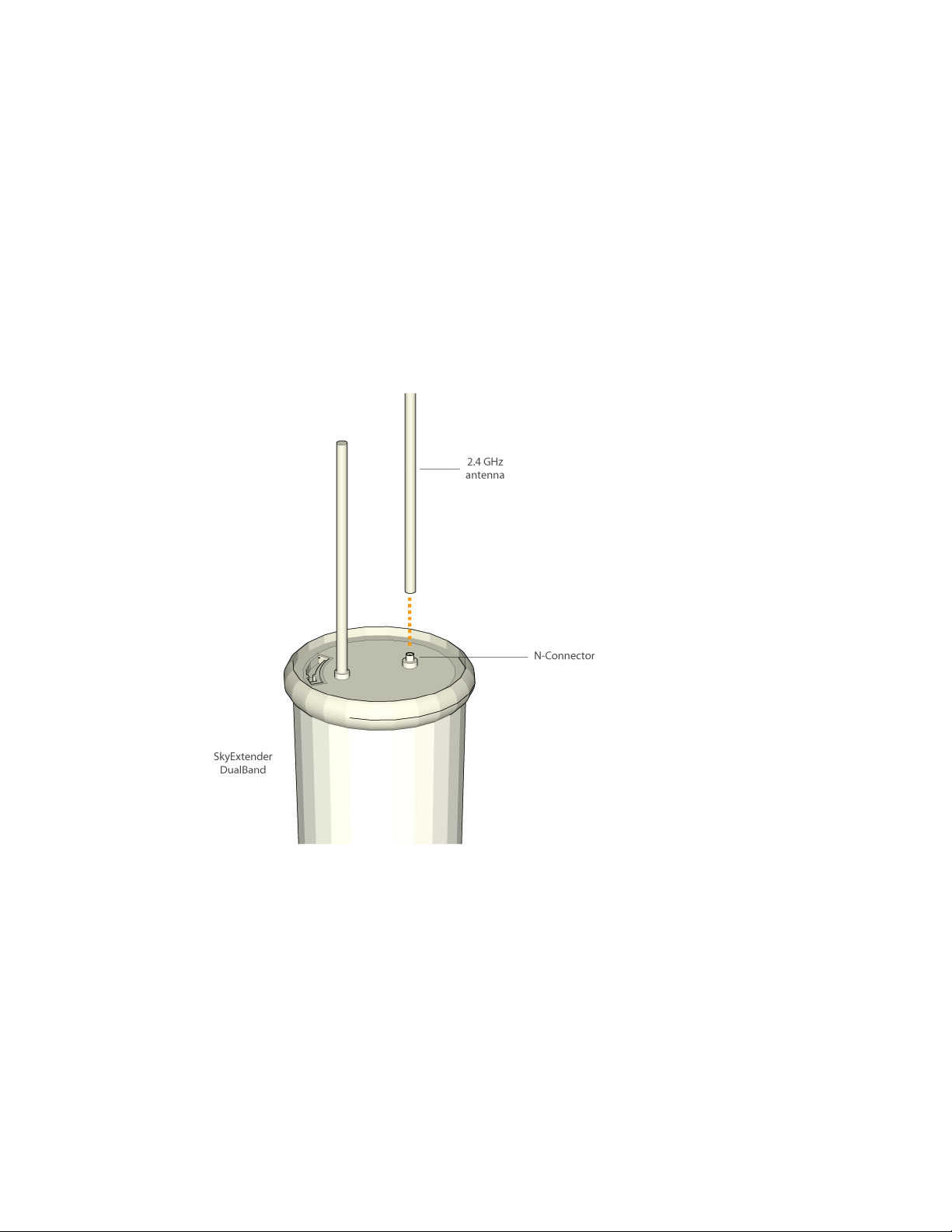
2
Connect the 2.4 GHz antennas.
The access point requires attachment of the two 2.4 GHz antennas included
with the device. Screw the antennas onto the standard N connectors on the
underside of the SkyExtender DualBand.
Figure 1. Attaching the antennas
SkyPilot SkyExtender DualBand Installation and Setup Guide 13
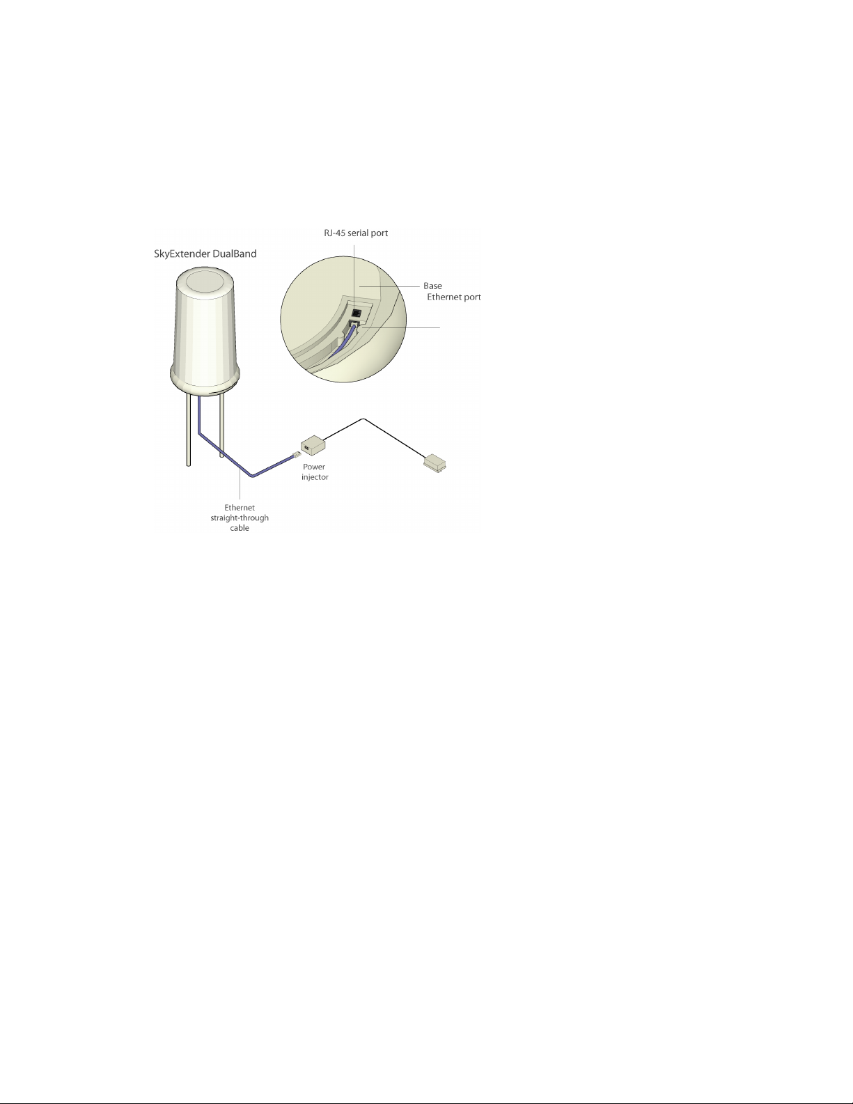
3
Connect the SkyExtender DualBand to the power supply.
Connect the Ethernet straight-through cable (provided) between the power
injector and the Ethernet port on the base of the SkyExtender DualBand.
Plug the AC adapter into the power injector.
Figure 2. Providing power to the SkyExtender DualBand
NOTE
The external Ethernet port on the SkyExtender DualBand is limited to
providing power to the device; it cannot handle data traffic. Do not
attempt to connect the power injector to a network switch or other
device.
Powering on
When power is supplied to the SkyExtender DualBand, it starts a routine power-
on sequence that you can monitor by observing the pair of LED lights on the
underside of the device.
While the device is initializing and searching for a GPS signal, both LED lights
blink four times in a repeating cycle.

SkyPilot SkyExtender DualBand Installation and Setup Guide
14
When the Link LED turns steady green and the Activity LED is off, the SkyExtender
DualBand is initialized and listening for hello signals from other devices. When
both LEDs are steady, the SkyExtender DualBand is successfully connected to the
wireless network.
The sequence takes about 15 minutes while waiting to acquire a GPS signal. (The
SkyExtender DualBand must have access to a GPS signal to complete the
sequence.)

SkyPilot SkyExtender DualBand Installation and Setup Guide 15
C on fi gu ri ng S ky Ex te nd er D ua lB an d
After installing the SkyExtender DualBand, you need to provide both the
SkyExtender and access point components of the device with configuration
information that they need for network operations.
This chapter tells you how to use the SkyPilot EMS software to configure the
SkyExtender DualBand for both mesh networking and Wi-Fi operation.
Before you begin
Before starting configuration, make sure the SkyExtender DualBand is powered
on and capable of receiving a signal from a SkyGateway or SkyExtender.
Additionally, make sure the EMS software is installed (both on a central server and
a client) and set up for configuring SkyPilot devices.
After getting a configuration from the provisioning server, the SkyExtender
DualBand will establish a link to the SkyGateway (or to another SkyExtender) and
use DHCP to retrieve an IP address and instructions for downloading
configuration information stored on the server.
Detailed procedures for using EMS software are provided in the SkyPilot Network
Administration Guide available on the SkyPilot Network Software CD or the SkyPilot
website at
www.skypilot.com
.
Automatic configuration versus manual configuration
The SkyExtender and access point contained in the SkyExtender require network
configurations to operate on the wireless mesh network. SkyPilot gives you a
4

SkyPilot SkyExtender DualBand Installation and Setup Guide
16
choice of two modes for provisioning devices with configurations: automatic or
manual.
Automatic provisioning requires the use of SkyPilot EMS software to create
configurations that an unattended central server can distribute to devices on the
wireless mesh network. Although automatic provisioning requires more setup
time than manual provisioning, it greatly simplifies the administration of a
growing network.
Usually performed in the field, manual provisioning permits the configuration of
only a single device at a time, creating the minimum settings required for a
wireless link and storing them in the device’s flash (nonvolatile) memory.
For more information on provisioning modes, see Getting Started with the SkyPilot
Network, provided on the SkyPilot Network Software CD.
Choosing a WLAN configuration
Before starting configuration, decide on the type of Wi-Fi network you want to
configure at the access point location.
Most WLAN deployments use one of two common types of WLAN configuration:
o
An open (unprotected) Wi-Fi network, which does not authenticate users or
which depends on authentication by a backend system such as a captive
portal
o
A Wi-Fi protected access (WPA) network, which uses standards-based client
authentication and encryption
NOTE
A WPA network requires a Radius server for authenticating users;
see the next section for information on setting up the server.
As you follow the steps for configuring the SkyExtender DualBand, the
procedures will direct you to the appropriate section depending on your type of
configuration.

SkyPilot SkyExtender DualBand Installation and Setup Guide 17
Setting up a Radius server for authenticating users
If you plan configure your SkyExtender DualBand access point for WPA, you must
first configure a Radius server with the following:
o
The IP address and shared secret of the SkyExtender DualBand access point.
o
EAP-PEAP/MSCHAPv2 and EAP-TTLS/PAP or MSCHAPv2 (not EAP-TLS) suitable
for WPA. Your Radius supplier can provide instructions.
o
A Users database with user names and passwords. You may also need to
identify a proxy Radius if you’re delegating some domains to other service
providers.
Preparing software images
The next steps for automatic configuration of the SkyExtender DualBand start
with preparing the software images, as described in this section, and continue
with the procedures described in the remaining sections of this chapter. For
information related to manual configuration, turn to Chapter 5, “Using the Access
Point Configuration Tool.”
Before you use the EMS software to set up automatic configuration of the
SkyExtender DualBand, make sure the most current software images are available
to the EMS client software. (You can identify software images by the prefixes and
version numbers in their names—for example,
SkyGate.2.0.14.bin
,
SkyConn.2.0.14.bin, SkyExt.2.0.14.bin
, and
SkyExtDB.2.0.14.bin
.)
To provide the EMS software with access to the software images, copy the
images to the directory
/var/ftp/pub/images/
on the provisioning server.
Starting the EMS client
After confirming that the current software images are in the appropriate
directory, you can run the EMS client software and start setting up automatic
configuration of the SkyExtender DualBand.
You‘ll run the EMS client software from a computer on the wireless mesh network
and use SkyProvision™ to set up a node profile for the SkyExtender DualBand.
SkyPilot SkyExtender DualBand Installation and Setup Guide
18
To start the EMS client software:
1
From the client computer, open the
C:\SkyPilot\EMS\bin\
directory.
2
Double-click the
startsemsclient.bat
application icon.
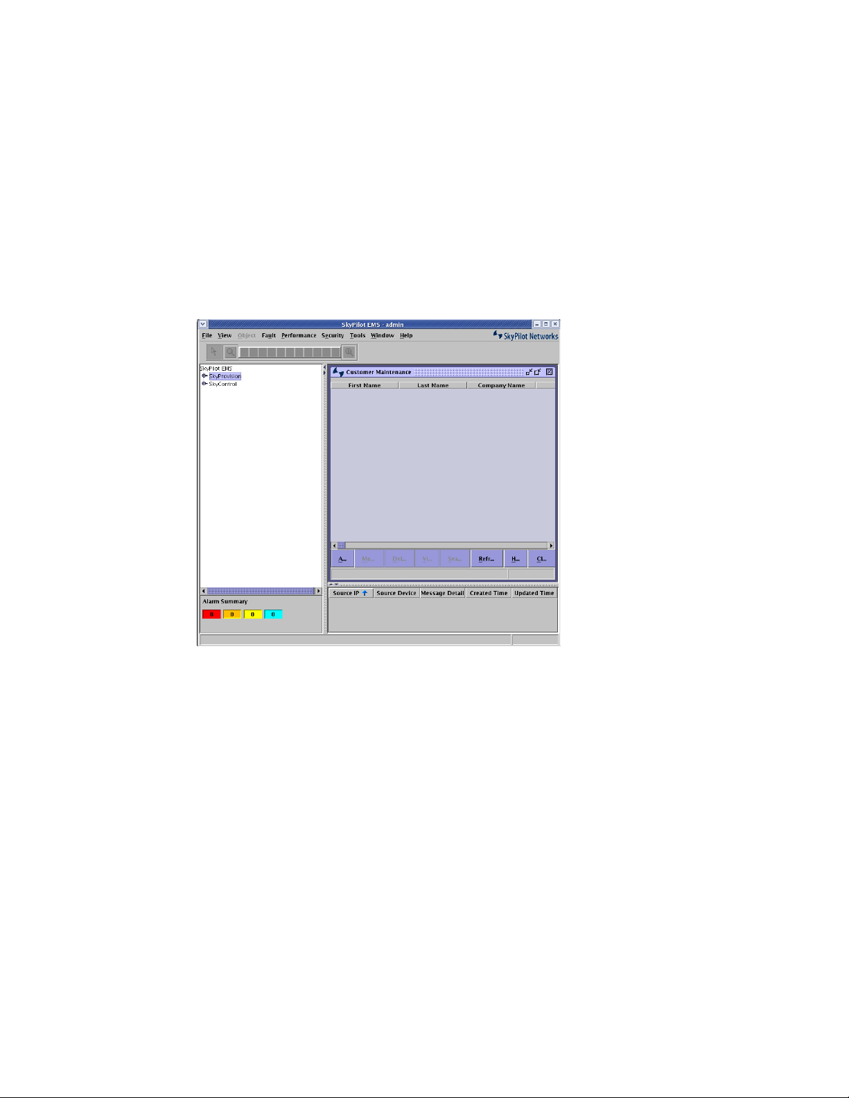
3
At the prompt, enter the user name and password.
The default user name is admin; the default password is admin.
The application starts, displaying the main menu.
Figure 3. EMS client window
The taskbar on the left side of the window expands to show options for using
the EMS applications: SkyProvision and SkyControl™.
SkyPilot SkyExtender DualBand Installation and Setup Guide 19
Adding software images
Using the SkyProvision application, you can view the software images that the
provisioning server will use to configure the new device and then add any as
needed.
1
Open the SkyProvision Software Maintenance pane.
In the taskbar, double-click
SkyProvision
>
Software
>
Software
Maintenance
—that is, click the expansion icon next to
SkyProvision
to view
all the application options, click the expansion icon next to the
Software
option, and then double-click
Software Maintenance
under that option.
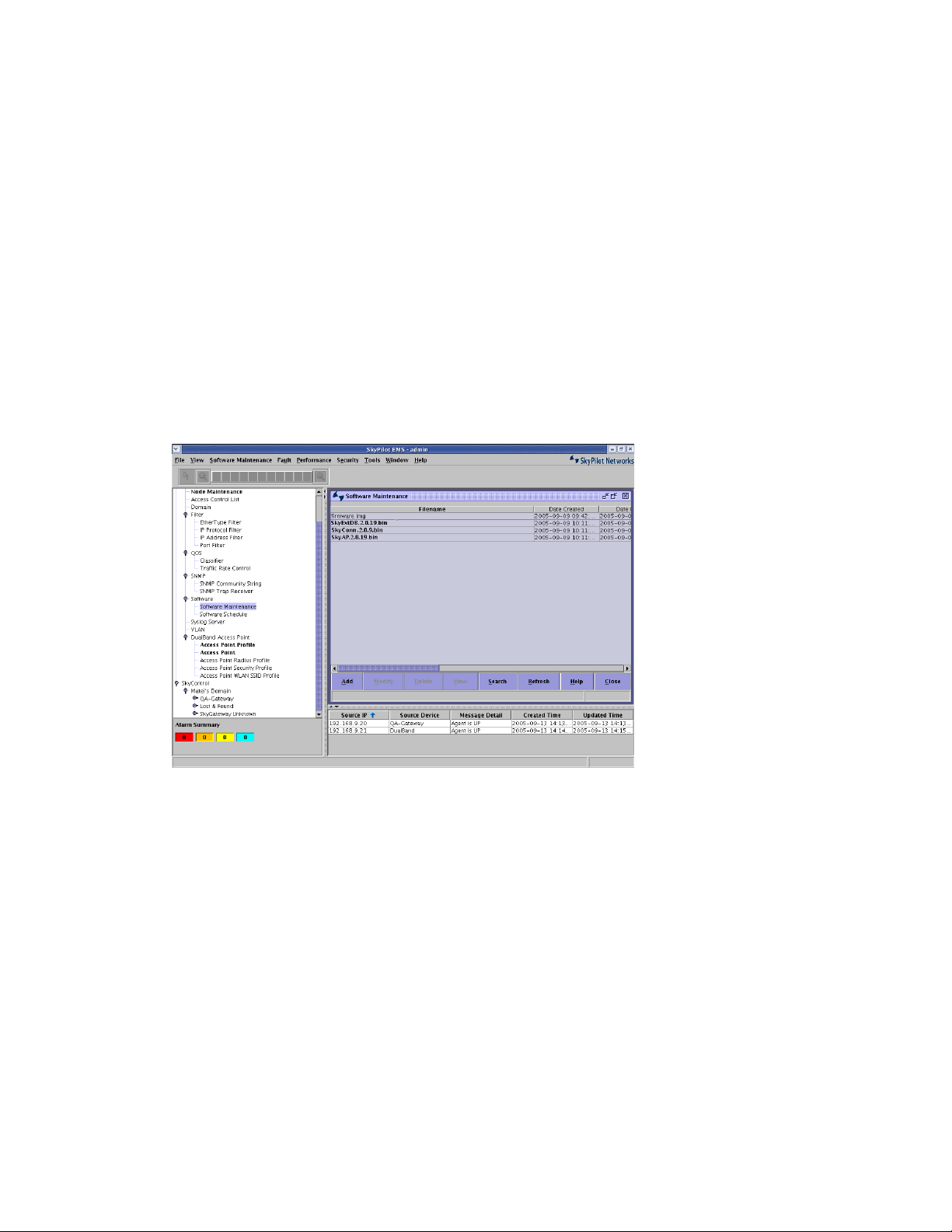
The Software Maintenance pane appears, listing currently loaded software
images.
Figure 4. Software Maintenance list
2
If necessary, add one or more software images.
Click the
Add
button below the Software Maintenance list to open the Add
Software dialog box.
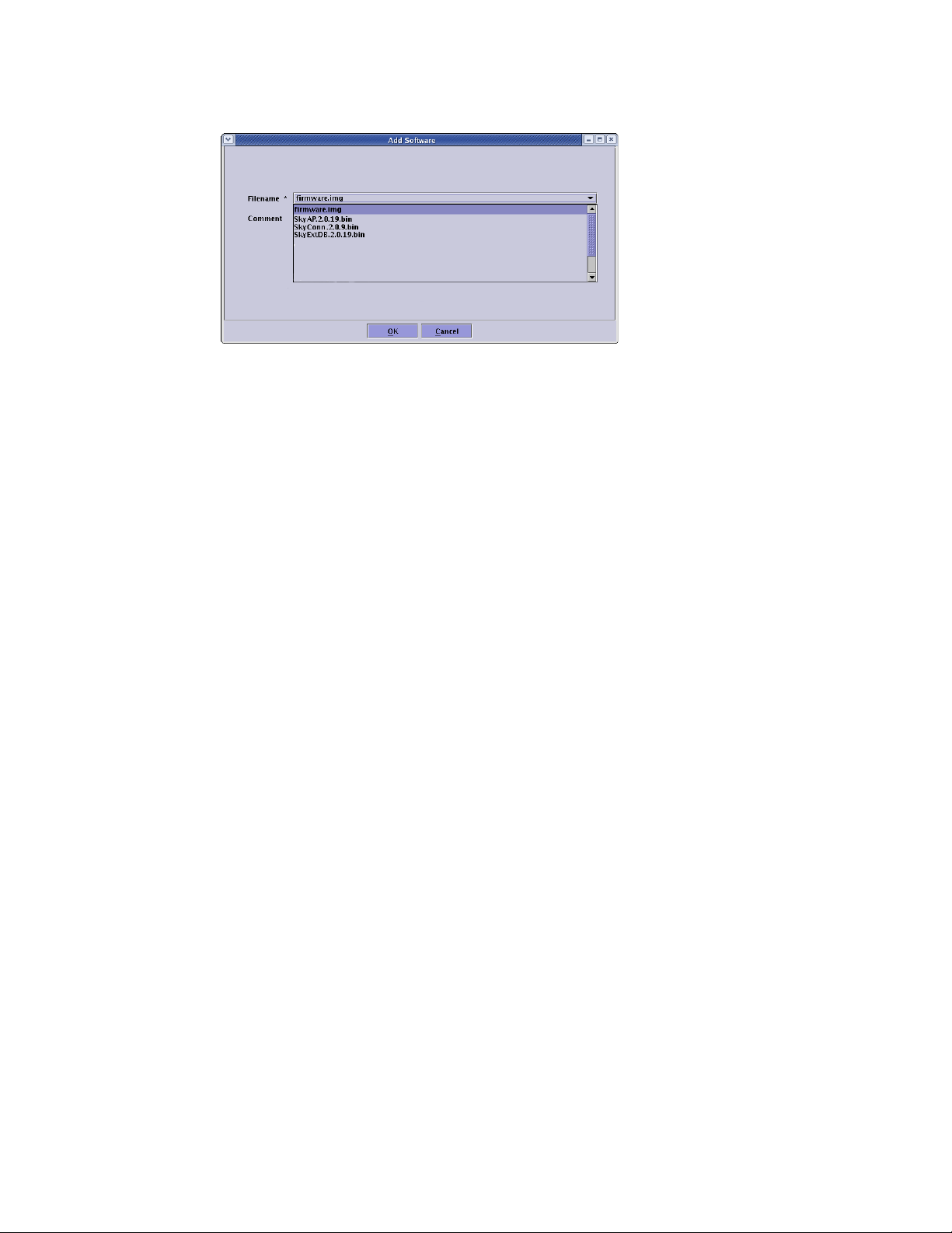
SkyPilot SkyExtender DualBand Installation and Setup Guide
20
Figure 5. Add Software dialog box
Select a software image from the list and click OK.
The selected image now appears in the Software Maintenance list.
Repeat step 2 to add additional software images.
Specifying a domain
After adding any software images as necessary, you need to specify a domain for
the SkyExtender DualBand that’s consistent with the domain assigned to the
SkyGateway operating as a hub for the wireless mesh network.
1
Open the SkyProvision Domain pane.
In the taskbar, double-click
SkyProvision
>
Domain
.
The Domain pane appears, listing currently active domains.
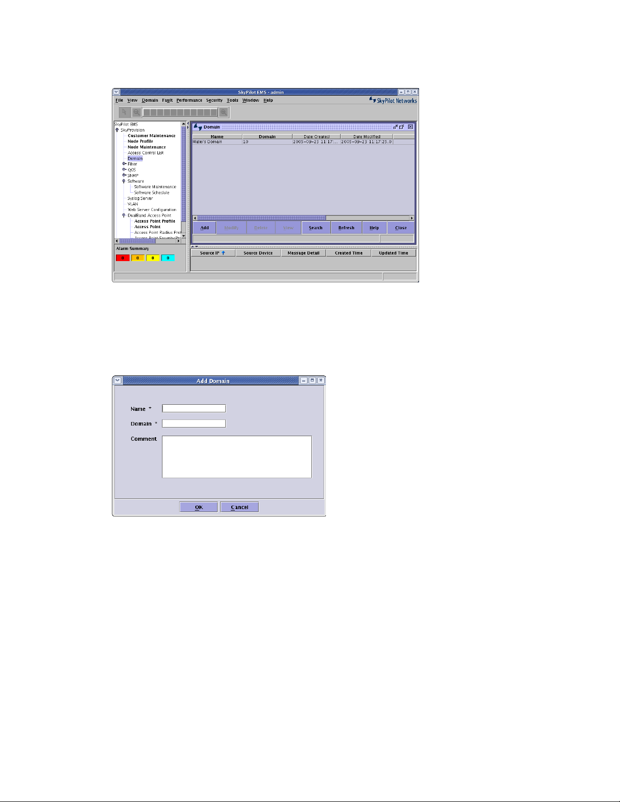
SkyPilot SkyExtender DualBand Installation and Setup Guide 21
Figure 6. Domain list
2
Add a domain.
Click the
Add
button below the Domain list to open the Add Domain dialog
box.
Figure 7. Add Domain dialog box
Enter a domain name and number, and then click OK. (The
Comment
field is
optional.)
The domain now appears in the Domain list.
SkyPilot SkyExtender DualBand Installation and Setup Guide
22
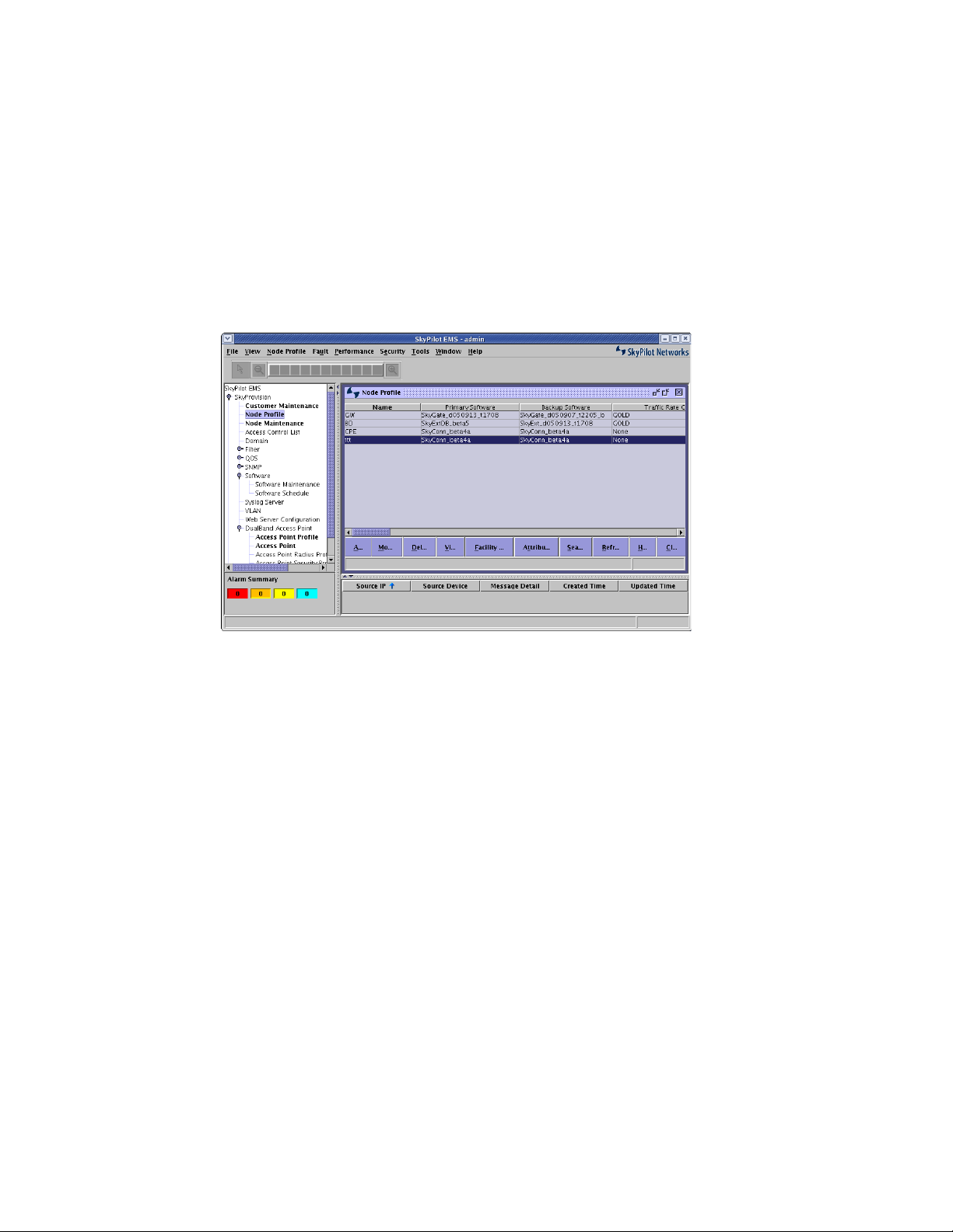
Creating a node profile
After confirming the availability of software images and the correct domain, your
next step is to create a node profile for the SkyExtender DualBand.
1
Open the Node Profile pane.
In the taskbar, double-click
SkyProvision
>
Node Profile
.
The Node Profile pane appears, listing existing node profiles.
Figure 8. Node Profile list
2
Add a new node profile.
Click the
Add
button below the Node Profile list to display the Add Node
Profile dialog box. (In this dialog box and similar ones, asterisks identify
required fields.).
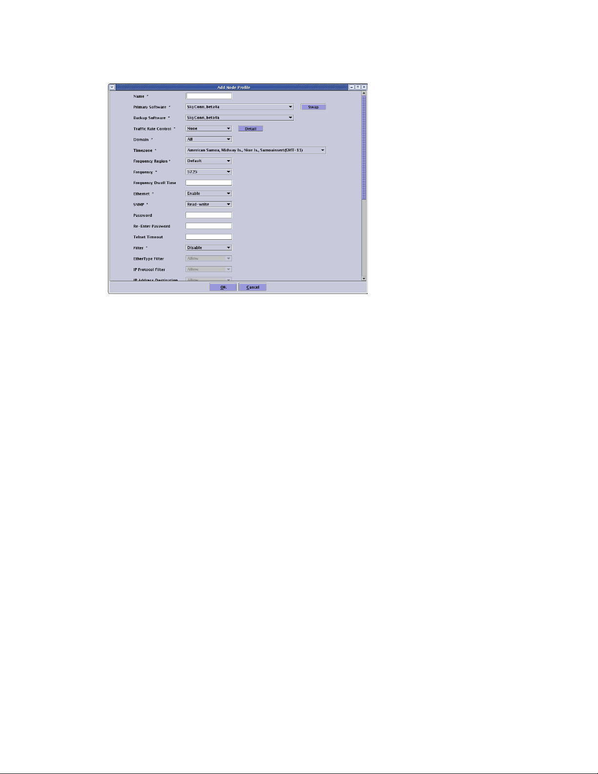
SkyPilot SkyExtender DualBand Installation and Setup Guide 23
Figure 9. Add Node Profile dialog box
Use the provided fields and pull-down menus to specify general operating
parameters for the profile, including a profile name, software images, domain,
Ethernet status, and operating frequency.
Click OK to save the settings.
The new node profile now appears in the Node Profile list.
Creating a node
After creating the node profile, you can specify the SkyExtender DualBand as a
new node on the wireless mesh network.
When you create a node and identify it as a SkyExtender DualBand, access point
options become available in the EMS client taskbar.
1
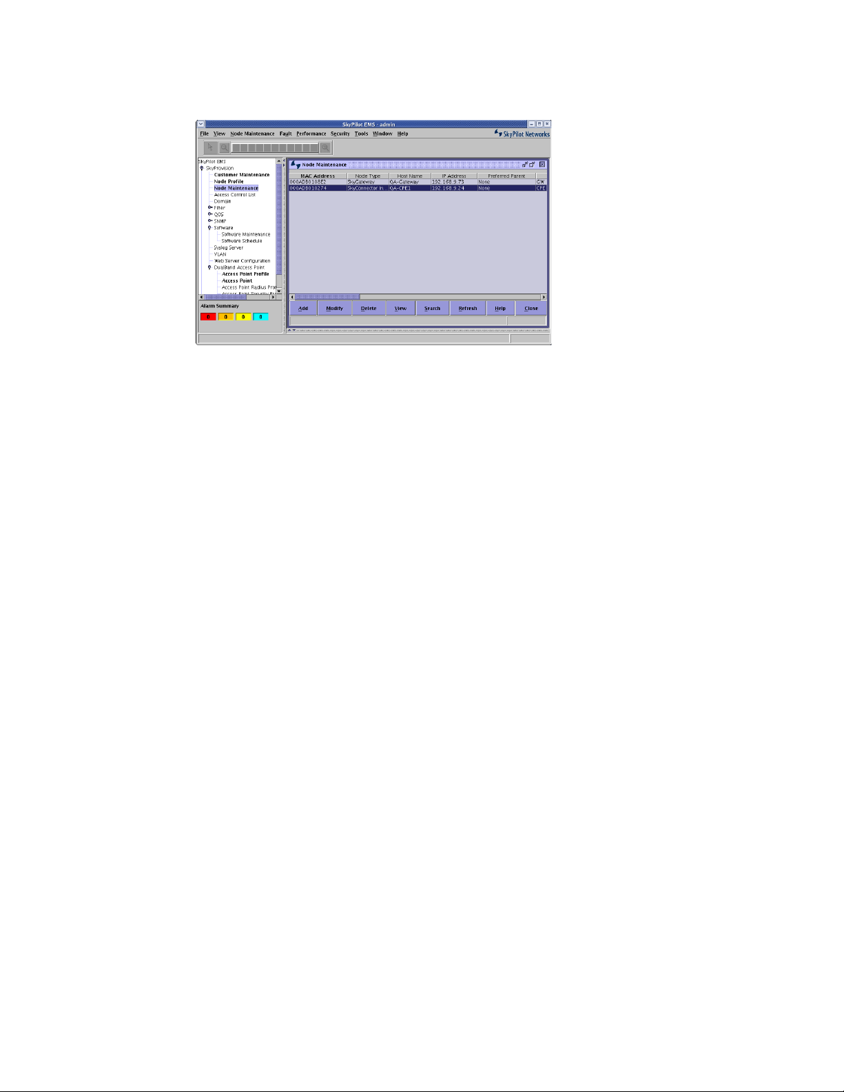
Open the Node Maintenance pane.
In the taskbar, double-click
SkyProvision
>
Node Maintenance
.
The Node Maintenance pane appears, listing existing nodes by MAC address
and node type. Figure 10 shows an example.
SkyPilot SkyExtender DualBand Installation and Setup Guide
24
Figure 10. Node Maintenance list
2
Add a new node.
Click the
Add
button below the Node Maintenance list to display the Add
Node dialog box. (Asterisks identify required fields.)
 Loading...