

Page 1
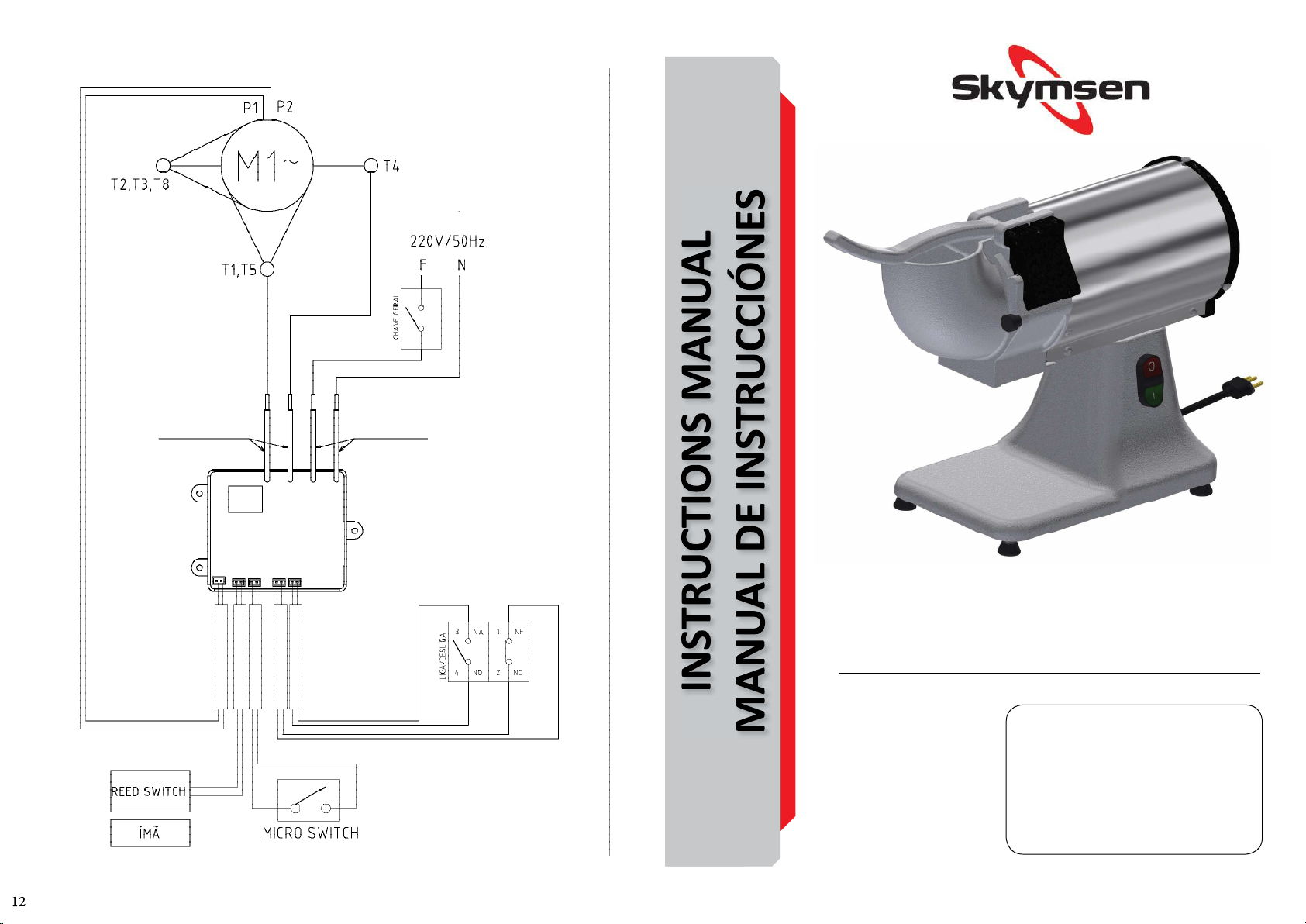
RED ELÉCTRICA
HIJOS AMARILLOS HIJOS NEGROS
PLACA
ELECTRONICA
ICE CRUSHER / TRITURADOR DE HIELO
MODEL/MODELO
TG
68678.6 - ENGLISH/ESPAÑOL
Data de Revisão: 13/05/2022
Metalúrgica Skymsen Ltda.
Rodovia Ivo Silveira 9525
Volta Grande
88355-202 Brusque/SC/Brasil
www.skymsen.com - Fone: +55 47 3211 6000
CNPJ: 82.983.032/0001-19 - IE 250.064.537
DUE TO THE CONSTANT IMPROVEMENTS INTRODUCED TO OUR EQUIPMENTS, THE INFORMATION CONTAINED IN THE PRESENT
INSTRUCTION MANUAL MAY BE MODIFIED WITHOUT PREVIOUS NOTICE.
Page 2
SUMMARY
1. INTRODUCTION .........................................2
1.1 Safety ......................................................2
2. COMPONENTS AND TECHNICAL
CHARACTERISTICS .........................................2
3. INSTALLATION AND PRE-OPERATION ..........3
3.1 Placing .....................................................3
3.2 Electrical Installaon ................................3
3.3 Equipotencial terminal .............................3
3.4 Safety System ..........................................3
4. OPERATION................................................3
4.1 Turning on the Appliance .........................3
4.2 Feeding Procedure ...................................3
5. CLEANING ..................................................3
6. MAINTENANCE ..........................................3
7. OBSERVED STANDARDS .............................4
8. SOLLUTION OF PROBLEMS .........................5
9. ELECTRICAL DIAGRAM ...............................6
1. INTRODUCTION
This product was developed to be used in commercial
kitchens. It is used, for example, in restaurants, cafeterias,
hospitals, bakeries, etc.
This appliance usage is not recommended when:
- The producon process should be done in a connuous
way in industrial scale;
- The workplace is in an atmosphere of corrosive, explosive,
with dust or gas.
1.1 Safety
The instrucons below must be followed to avoid accident.
Not following them must cause serious injuries:
1.1.1 Never use the appliance with: wet clothes and feet
and/or in wet surfaces, do not dip it into water or any other
liquid and do not use directly into water jet.
1.1.2 If the appliance falls or it is in any way damaged, it is
necessary to take it to an Authorized Technical Assistance.
1.1.3 The use of accessories not recommended by the
manufacturer may cause bodily injury.
1.1.4 The usage of non-authorized accessories that are not
recommended by the manufacturer may cause injuries.
Keep your hands and any utensil far from the parts in
movement of the appliance while in operaon to avoid body
injuries or damage to the appliance.
1.1.5 Never use loose sleeves while operang the appliance.
1.1.6 Make sure that the electrical tension of the appliance
and the power grid are the same and that the appliance is
connected to the grounding grid.
This appliance is not intended to be used by
people(including children) with reduced physical, sensorial
and mental capacity or used by people with lack of
experience and knowledge, unless the person has had
instrucons related to the usage of the appliance or be
under supervision of a person who is responsible for his/
her safety.
It is recommended that the kids are being watched so
that they don´t use the appliance.
Never put the finger in the feeding place and food
unloading.
Unplug the appliance from the power grid when:
it is not being used, before cleaning it, when adding or
removing accessories, maintenance or any kind of service.
Do not use this appliance if the plug or cable are
damaged. Make sure that the power cable does not stay
on the edge of the table/counter or that it touches hot
surfaces.
In case of emergency, disconnect the plug from the
outlet.
2. COMPONENTS AND TECHNICAL
CHARACTERISTICS
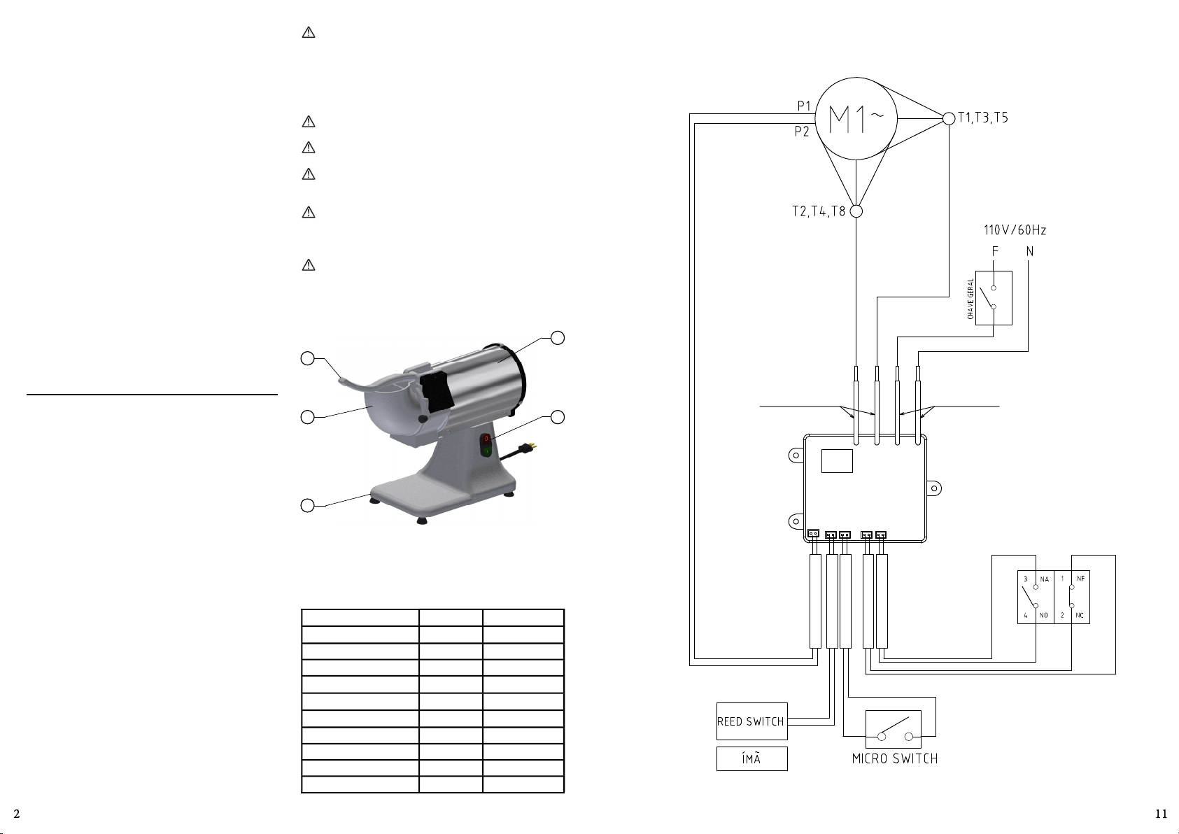
01
02
03
01 – Pusher
02 – Feed Inlet
03 – Base
04 – ON/OFF Switch
05 – Motor Housing
Picture 01
05
04
Table 01
CHARACTERISTICS Unity TG
Tension V 110 or 220
Frequency Hz 50 or 60
Power CV 0,5
Height mm 420
Width mm 200
Depth mm 570
Net weight Kg 15,5
Gross Weight Kg 17
Disc Rotaon RPM 1750
Producon kg 50
9. DIAGRAMA ELÉCTRICO
RED ELÉCTRICA
HIJOS AMARILLOS HIJOS NEGROS
PLACA
ELECTRONICA
ENCENDE/APAGA
Page 3
8. SOLUCIÓN DE PROBLEMAS
PROBLEMAS CAUSAS SOLUCIOES
-Procedimiento de accionamiento incorrecto.
- Protector térmico del motor está actuando.
- El equipamiento no enciende.
- El equipamiento enciende,
pero al colocar el producto
dentro de él, para de funcionar
o gira en baja rotación.
- El producto queda preso en el
interior del equipamiento.
- Olor a quemado e/o humo.
- Cable eléctrico dañado. - Falla en el transporte del producto.
- Ruidos anormales. - Problemas con rodamientos.
- El Conducto de Alimentación está abierto.
- Problema en el circuito eléctrico interno o
externo del equipamiento.
- Falta de energía eléctrica.
- Problemas con el Motor Eléctrico.
- Conducto de Salida obstruido. - Desobstruya el Conducto de Salida.
- Problema en el circuito eléctrico interno o
externo del equipamiento.
- Lea el ítem 4.1 - Accionamiento
- Aguarde algunos minutos e intente
nuevamente.
- Cierre el Conducto de Alimentación.
- Llame a la Asistencia Técnica
Autorizada (ATA).
- Verifique si existe energía eléctrica.
- Llamar a la Asistencia Técnica
Autorizada (ATA).
- Llamar a la Asistencia Técnica
Autorizada (ATA).
- Llamar a la Asistencia Técnica
Autorizada (ATA).
- Llamar a la Asistencia Técnica
Autorizada (ATA).
3. INSTALLATION AND PRE-OPERATION
3.1 Placing
Your appliance must be posioned and leveled on a dry and
firm surface with a preferable height of 850 m.
3.2 Electrical Installaon
The feeding cable has 3 pins, and the central pin is for
grounding. It is mandatory that the 3 pins are turned on
before turning on the appliance.
3.3 Equipotencial terminal
The Picture presented below indicates the external
equipotenal terminal.
It must be used to guarantee that there is no potenal
difference between different equipment connected to the
power grid, diminishing the risk of electric shocks.
The disnct equipment must be turned on one to the other
by their own equipotenal terminals.
Picture 02
Terminal
3.4 Safety System
For the safety of the operator, this appliance has 3 devices
that are capable of turning off the machine and prevenng
accidents.
a – The first one turns the machine off automacally
when removing the feeding nozzle. When returning to the
posion, the machine doesn´t work again.
b – The second device interrupts the operaon of the
machine when the pushing boom is on, opening the
feeding nozzle. When the pushing boom returns to its
posion, the machine starts automacally to work
c – The third one turns off the machine motor in the case
of overheang. Wait for some me unl the machine cools
down and turn it on again on the turn on buon.
4. OPERATION
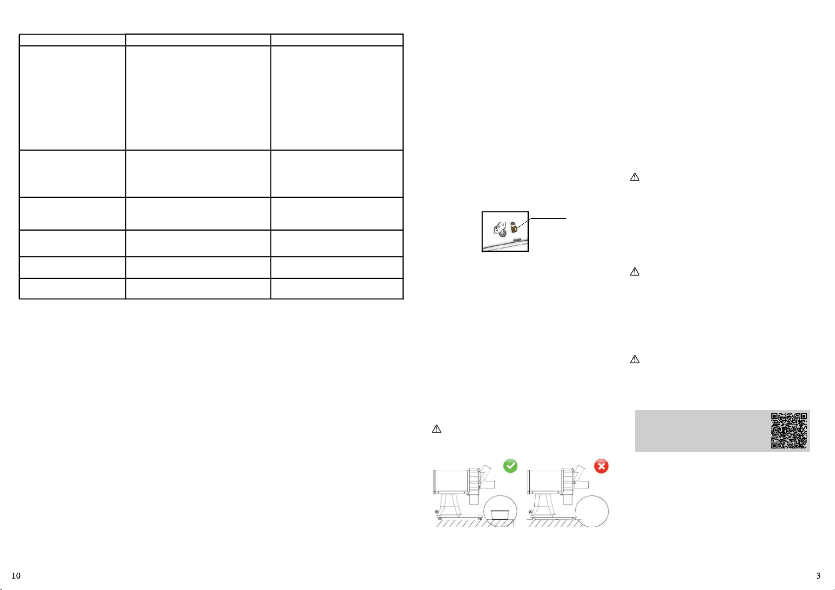
Never operate this appliance when close to the border
of the work surface.
Picture 04
• Check if the appliance is firm to the working area.
• Before using the appliance, it is necessary to wash all
the components that have contact with the product
that will be processed, with water and neutral soap.
4.1 Turning on the Appliance
Before turning on the equipment, check the following
procedures:
- Check if the feeding mouth is closed and correctly locked;
- Check if the pushed is correctly posioned inside the
nozzle.
To start the appliance, press the Turn ON Switch so that the
appliance starts working.
4.2 Feeding Procedure
Under no circumstance, use the instruments to push
the product to be processed to the Feeding Nozzle No.
02 (Picture 01), much less the hands. Use the pusher No.
01(Picture 01) to make the referred operaon.
The Ice Crusher is a machine that Works in high velocity, and
it also needs the feeding to be fast.
To feed it, li up the pusher No. 1 (Picture 01) e put the
product to be processed inside the feeding nozzle No. 02
(Picture 01) pushing it down, with the help of a pusher.
The product leaves because of the gravity. The cleaning
of the interior of the box and the outlet nozzle, Exit Nozzle
and the exit Nozzle to avoid obstrucon.
5. CLEANING
Step 1: Turn the plug from the outlet;
Step 2: Make the disassembling of the removable parts;
Step 3:Wash the removable parts with warm water and
neutral.
Never use water jet directly to the appliance.
Step 4: When washing the disc, handle it with care. Never
throw the disc against other objects, to preserve the blades.
Step 5: Wipe the Box and the Disc with warm water and
neutral soap.
Scan the QR Code to get informaon
about special care with stainless steel.
6. MAINTENANCE
The maintenance must be a group of procedures that have
the objecve of keeping the appliance in it best condion of
operaon. Increasing its life expectancy and safety.
* Cleaning – Check the item 5 Cleaning of this Manual.
* Electrical wiring – Check all the cables to avoid deterioraon
and all the electrical contacts about their ghtening and
corrosion
* Contacts – Turn on and off boom,, emergency boom,
reset boom, electric circuits, etc. Check the appliance so
that all the components are working correctly and that the
operaon is working normally
Page 4
* Installaon – Check the installaon of your appliance
according to the item 2 Installaon and Pre-Operaon of
this manual.
1 – Items to be verified and implemented monthly:
- Check the electrical installaon;
- Check the outlet tension;
- Measure the operang current and compare it to the
nominal;
- Check all the eletrical terminal ghtening of the appliance,
to avoid bad contact;
- Check the possible clearance of the sh of the electric
motor;
- Check the wiring and the eletric cable to avoid its
overheang, deficient isolaon and mechanical breakdown
2 - Items to be verified and implemented monthly:
- Check the electric components as turn on/off boom,
emergency buon ,reset buon, and eletric circuit related to
overheang, deficient isolaon and mechanical breakdown.
- Check possible loosens in the bearings
- Check retainers, o´rings, v´rings and other sealing systems
- Check that all screws and nuts are ght to avoid possible
damage to the equipment.
Scan the QR Code to get informaon
about safety and maintenance.
8. SOLLUTION OF PROBLEMS
PROBLEMS CAUSES SOLUTIONS
- The appliance
does not turns
on.
- The appliance
turns on, but
when pung the
product in the
appliance, it turns
in low rotaon.
- The product is
stuck inside the
appliance.
- Burn and smoke
smell
- Damaged
electrical cable
- Awkward noise
- Wrong
acvaon
procedure.
- Motor thermal
protector is
working.
- The feeding
nozle is open;
- Problem in
the internal or
external eletrical
circuit of the
appliance;
- Power shortage.
- Problems with
the Electric
Motor.
- Obstructed
outlet nozzle
- Problem in
the internal or
external electric
circuit of the
appliance.
- Problems
with the
transportaon of
the appliance.
- Problems with
rolling bearing.
- Read the item
4.1 – Acvaon;
- Wait for some
minutes and try
again;
- Close the
feeding nozzle;
- Call the
Authorized
Technical
Assistance;
- Check if there is
electric power.
- Call the
Authorized
Technical
Assistance.
- Clear the outlet
nozzle.
- Call the
Authorized
Technical
Assistance.
- Call the
Authorized
Technical
Assistance.
- Call the
Authorized
Technical
Assistance.
- Verificar la instalación eléctrica;
- Medir la tensión del tomacorriente;
- Medir la corriente de funcionamiento y comparar con la
nominal;
- Verificar aprietes de todos los terminales eléctricos del
aparato a fin de evitar posibles malos tratos;
- Verificar posibles holguras del eje del motor eléctrico;
- Chequear el cableado y el cable eléctrico cuando haya
señales de supercalentamiento, aislación deficiente o avería
mecánica.
2 - Ítems a verificar o ejecutar a cada 3 meses:
- Verificar componentes eléctricos como el interruptor
encender/apagar, botón de emergencia, botón reset/
reinicio y circuito electrónicos cuando haya señales de
supercalentamiento, aislación deficiente o avería mecánica.
- Verificar posibles holguras en los cojinetes y rodamientos.
- Verificar retenes, anillos o’rings, anillos v’rings y demás
sistemas de sellamiento.
-Verifique el apriete de todos los tornillos y tuercas para
evitar posibles daños al equipo.
7. NORMATIVA APLICABLE
ABNT NBR NM 60335-1
IEC 60335-2-64
Escanee el QR Code al lado para obtener
informaciones básicas sobre la seguridad
y manutención.
Page 5
3. INSTALACIÓN Y PRE-OPERACIÓN
3.1 Posicionamiento
Su equipamiento debe ser posicionado y nivelado sobre
una superficie seca y firme con 850 mm de altura,
preferencialmente.
3.2 Instalación eléctrica
El cable de alimentación posee 3 dientes, de los cuales el
diente central se desna a la toma a erra. Es obligatorio
que los tres dientes estén debidamente conectados antes de
accionar el equipamiento.
3.3 Terminal equipotencial
La figura mostrada abajo indica el terminal de conexión
equipotencial externo.
Debe ser ulizado para garanzar que no haya diferencia
de potencial entre diferentes equipamientos conectados a
la red eléctrica, disminuyendo al máximo riesgos de choque
eléctrico.
Los disntos equipamientos deben estar conectados
uno al otro por sus respecvos terminales de conexión
equipotencial.
Figura 02
Terminal
3.4 Sistema de seguridad
Para la seguridad del operador, este equipamiento posee
tres disposivos capaces de desconectar la máquina para
prevenir accidentes.
a - El primero apaga la máquina automácamente al rerar
el Conducto de Alimentación. Al retornar la posición la
máquina no vuelve a funcionar.
b – El segundo disposivo interrumpe el funcionamiento
de la máquina cuando el empujador es levantado, abriendo
el conducto de alimentación. Al retornar el empujador a su
posición, la máquina vuelve a funcionar automácamente.
c – El tercer disposivo apaga el motor de la máquina si hay
supercalentamiento. Espere algunos minutos hasta que la
máquina se enfríe y vuelva a encender presionando el botón
Encender.
4. OPERACIÓN
Nunca opere el equipamiento cuando está colocado
próximo al borde de la superficie de trabajo.
Figura 04
• Verifique si el equipamiento está firme en su local de
trabajo.
• Antes de ulizar el equipamiento, deberán lavarse con
agua y jabón neutro, todas las partes que entran en
contacto con el producto que será procesado.
4.1 Accionamiento
Antes de encender el equipamiento:
- Verifique si el Conducto de Alimentación está cerrado y
correctamente trabado;
- Verifique si el Empujador está correctamente posicionado
dentro del Conducto;
Para accionar el equipamiento, presione el Interruptor
Encender para que el equipamiento comience a funcionar.
4.2 Procedimiento para Alimentación
Bajo ninguna circunstancia ulice instrumentos
para empujar el producto a procesar para el interior del
Conducto de Alimentación Nº02 (Fig. 01), mucho menos
las manos. Ulice el Empujador Nº 01 (Fig.01) para realizar
esta operación.
El Triturador de Hielo es una máquina que trabaja en alta
velocidad y, para ello, necesita que la alimentación sea
igualmente rápida.
Para alimentarlo, levante el Empujador Nº 01 (Fig.01) y
coloque el producto a procesar dentro del Conducto de
Alimentación Nº 02 (Fig. 01), empujándolo para abajo,
siempre con auxilio del Empujador.
La salida de los productos ocurre por gravedad. Se
debe efectuar regularmente la limpieza en el interior de
la Cámara y en el Conducto de Salida a fin de evitar su
obstrucción.
Escanee el QR Code al lado para obtener
informaciones sobre cuidados con
aceros inoxidables.
6. MANTENIMIENTO
La manutención comprende un conjunto de procedimientos
con el objevo de mantener el equipamiento en las mejores
condiciones de funcionamiento, permiendo el aumento de
su vida úl y de la seguridad.
* Limpieza – Verificar el ítem 5 “Limpieza” de este
manual.
* Cableado: Revisar todos los cables para corroborar
posible deteriorización y todos los contactos (terminales)
eléctricos para verificar posibles aprietes y corrosión.
* Contactos – Interruptor encender/apagar,
botón de emergencia, botón reset/restablecer, circuitos
electrónicos, etc. Verifique el equipamiento para que todos
los componentes estén funcionando correctamente y que la
operación del aparato sea normal.
* Instalación – Verifique la instalación de su
equipamiento según el ítem 2 Instalación y Pre-Operación de
este manual.
1 - Ítems a verificar y ejecutar mensualmente:
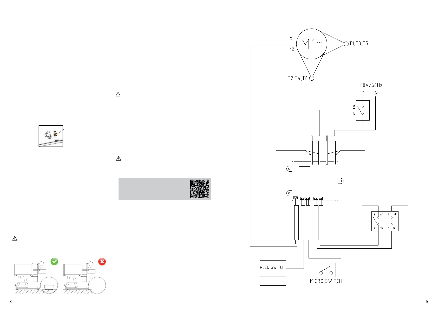
9. ELECTRICAL DIAGRAM
POWER GRID
YELLOW WIRE BLACK WIRE
CIRCUIT
BOARD
ON/OFF
MAGNET
Page 6
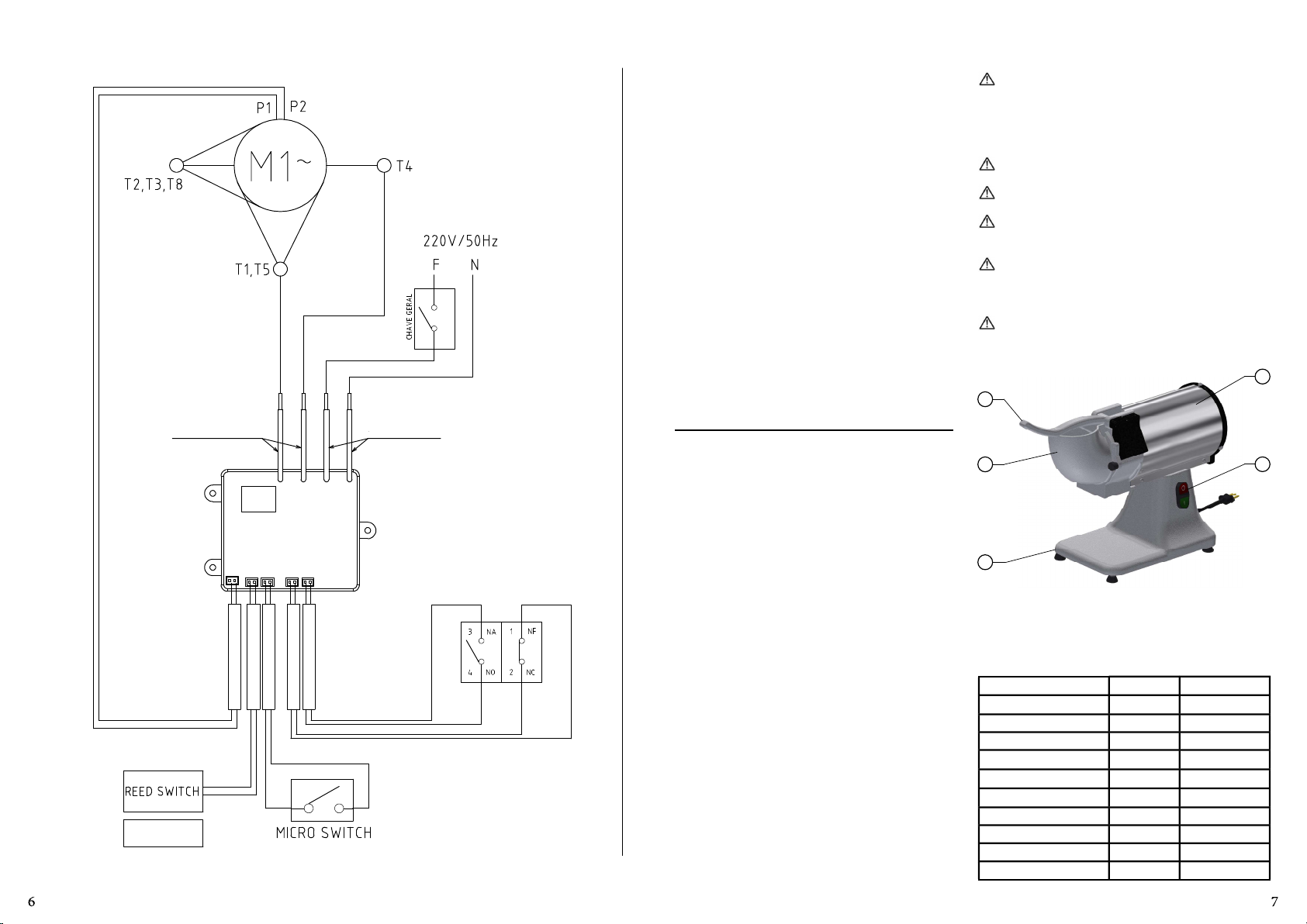
MAGNET
YELLOW WIRE
CIRCUIT
BOARD
POWER GRID
BLACK WIRE
1.1.6 Verifique que la tensión del equipamiento y de la
ÍNDICE
1. INTRODUCCIÓN .........................................2
1.1 Seguridad ................................................2
2. COMPONENTES Y CARACTERISTICAS
TÉCNICAS ......................................................2
3. INSTALACCIÓN Y PRE-OPERACIÓN ..............3
3.1 Posicionamiento ......................................3
3.2 Instalación Eléctrica .................................3
3.3 Terminal equipotencial ............................3
3.4 Sistema de Seguridad ...............................3
4. OPERACIÓN ...............................................3
4.1 Accionamiento .........................................3
4.2 Procedimiento de Operación....................3
5. LIMPIEZA ...................................................3
6. MANTENIMIENTO ......................................3
7. NORMATIVA APLICABLE .............................4
8. SOLUCIÓN DE PROBLEMAS ........................5
9. DIAGRAMA ELÉCTRICO ..............................6
1. INTRODUCIÓN
Este producto fue desarrollado para el uso en cocinas
comerciales. Es ulizado, por ejemplo, en restaurantes,
cannas, hospitales, panaderías y similares.
La ulización de este equipamiento no es recomendada
cuando:
- El proceso de producción sea de forma connua en escala
industrial.
- El local de trabajo sea un ambiente con atmósfera corrosiva,
explosiva, contaminada con vapor, polvo o gas.
1.1 Seguridad
Las instrucciones a seguir deben ser acatadas para evitar
accidentes. Su incumplimiento puede causar lesiones
graves:
ON/OFF
1.1.1 Nunca ulice el equipamiento con: ropas o pies
mojados e/o en superficies húmeda o mojadas. No sumerja
en agua o en cualquier otro líquido y no ulice chorro de
agua directamente en el equipamiento.
1.1.2 Cuando el equipamiento sufra una caída, esté dañado
de alguna forma o no funcione, es necesario llevarlo hasta
una Asistencia Técnica Autorizada.
1.1.3 La ulización de accesorios no recomendados por el
fabricante, puede ocasionar lesiones corporales.
1.1.4 Mantenga las manos y cualquier utensilio alejado
de las partes en movimiento del aparato mientras está en
funcionamiento para evitar lesiones corporales o daños al
equipamiento.
1.1.5 Nunca use ropas con mangas anchas, principalmente
en los puños durante la operación.
red eléctrica sean las mismas y que el equipamiento esté
debidamente conectado a la red de toma a erra.
Este equipamiento no es apto para ser ulizado
por niños ni personas con discapacidad sica, sensorial
o psíquica, o que carezcan de la experiencia y los
conocimientos necesarios. Excepto cuando lo hagan bajo
la supervisión de una persona responsable de su seguridad
o que les haya instruido en el manejo.
Se recomienda mantener a los niños bajo vigilancia
para garanzar que no jueguen con el aparato.
Nunca introduzca los dedos en los locales de
alimentación y de eyección de alimentos.
Desconecte el equipamiento de la red eléctrica cuando:
no esté en uso, antes de limpiarlo, inserción o extracción de
accesorios, manutención y cualquier otro po de servicio.
No ulice el equipamiento si está con el cable o enchufe
dañado. Asegúrese que el cable de energía no permanezca
en el borde de la mesa/mesada o que toque superficies
calientes.
En caso de emergencia, desconecte el enchufe del
tomacorriente.
2. COMPONENTES Y CARACTERÍSTICAS TÉCNICAS
01
02
03
01 – Empujador
02 – Conducto de
Alimentación
03 – Base
Figura 01
04 – Interruptor Encender/
Apagar
05 – Gabinete
05
04
Tabla 01
CARACTERÍSTICAS UNIDAD TG
Tensión V 110 ó 220
Frecuencia Hz 50 ó 60
Potencia W 0,5
Altura mm 420
Ancho mm 200
Profundidad mm 570
Peso Neto Kg 15,5
Peso Bruto Kg 17
Rotación del disco RPM 1750
Producción kg 50
 Loading...