

Page 1
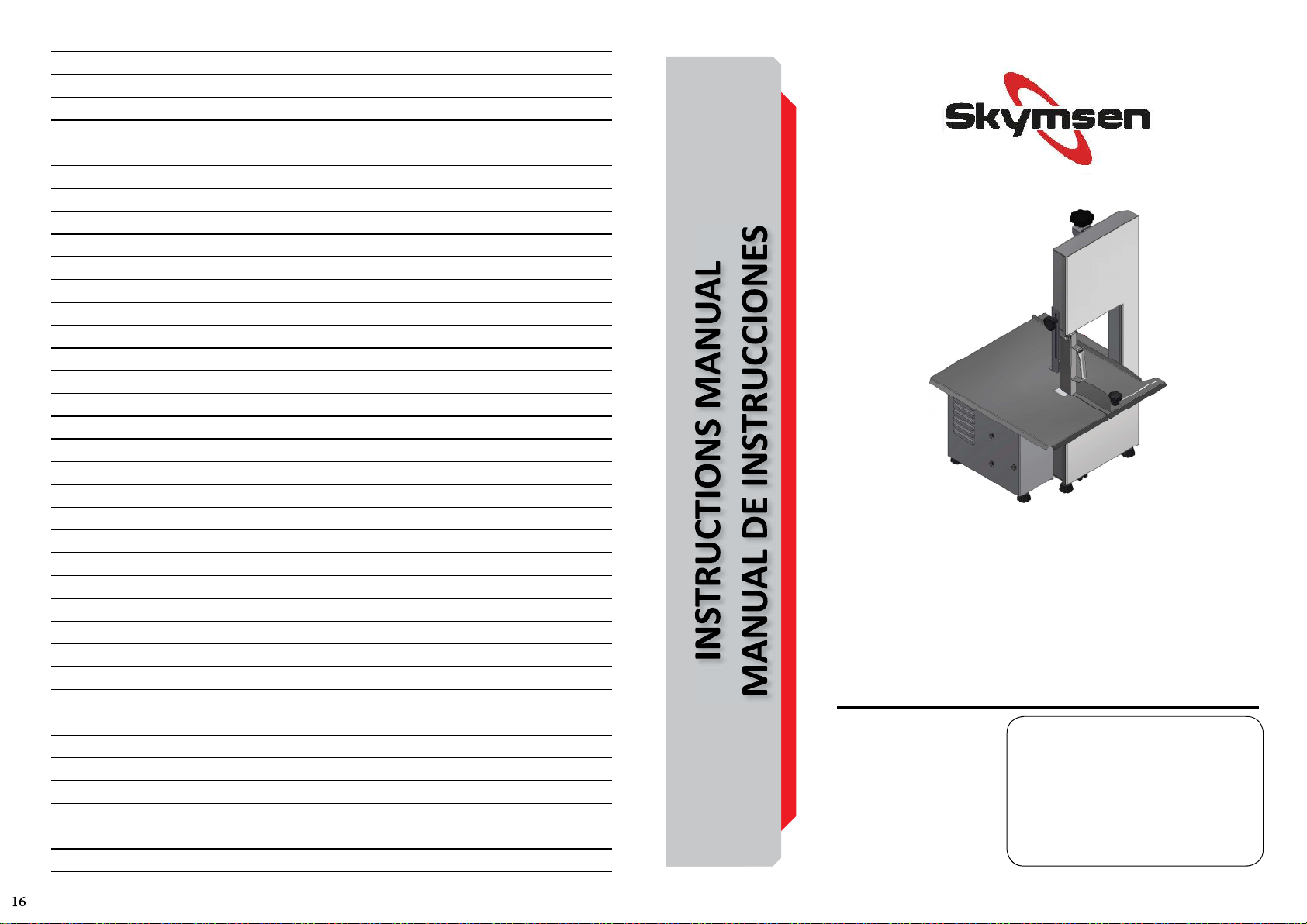
TABLE BAND SAW, STAINLESS STEEL, WITH CUT REGULATOR, BLADE 1.740
MM / 68,5”
SIERRA DE BANCADA PARA HUESOS, INOXIDABLE, CON REGULADOR DE
CORTE, CINTA 1.740 MM / 68,5”
MODEL/MODELOS
SB
SBL
70016.5 - ENGLISH/ESPAÑOL
Data de Revisão: 14/12/2021
Metalúrgica Skymsen Ltda.
Rodovia Ivo Silveira 9525
Volta Grande
88355-202 Brusque/SC/Brasil
www.skymsen.com - Fone: +55 47 3211 6000
CNPJ: 82.983.032/0001-19 - IE 250.064.537
DUE TO THE CONSTANT IMPROMEVENTS INTRODUCED TO OUR EQUIPMENTS, THE INFORMATIONS CONTAINED IN THIS
MANUAL MAY BE MODIFIED WITHOUT PREVIOUS NOTICE.
Page 2
SUMMARY
1. INTRODUCTION .............................2
1.1 Safety .....................................................2
2. MAIN COMPONENTS AND TECHNICAL
CHARACTERISTICS .............................2
3.INSTALLATION AND PRE-OPERATION ..3
3.1 Placing .................................................... 3
3.2 Electrical Installaon ............................... 3
3.3 Pre-Operaon ......................................... 3
4. OPERATION....................................3
4.1 Starng ...................................................3
4.2 Operaon Procedures ............................. 3
4.3 Safety System ......................................... 4
5. CLEANING ......................................4
6. MAINTENANCE ..............................5
7. PROBLEMS RESOLUTION ................5
8. ELECTRICAL DIAGRAMS ..................6
1. INTRODUTION
This equipment has been developed for commercial
operaon, it is used for instance in restaurants, fast foods,
hospitals, bakeries, butchers and similar.
It is not recommended to use it:
- The producon process is done in a connuous industrial
scale;
- The workplace is in a corrosive, explosive, contaminated
with vapor, powder or gas atmosphere.
1.1 Safety
The instrucons below must be followed to avoid accidents,
non-compliance can cause serious injuries:
1.1.1 Never use this Equipment with wet clothes or wet
feet or on a wet or humid surface, do not immerse it under
water, do not place under any kind of water flow, hose, tap or
similar, do not use water jets of any kind on the equipment.
1.1.2 If the Equipment physically falls down, in any way,
suffers any kind of damage or has stopped working for any
reason, it is necessary to call specialized technical assistance.
1.1.3 The use of unauthorized accessories that are not
recommended by the manufacturer can lead to injuries.
1.1.4 Keep hands or any kind of tools away from the moving
parts of the Equipment while it is turning on to avoid
potenal damages to the Equipment and injuries to the end
user.
1.1.5 Never operate the Equipment while wearing clothes
with long sleeves, especially on the wrists.
1.1.6 Make sure that the voltage of Equipment and of
the local electrical supply match. Also make sure that the
equipment is properly grounded.
1.1.7 Never adjust the Blade Guide nor the Thickness Guide
with the machine running.
This Equipment cannot be operated by persons
(children included) with reduced mental, sensorial or
physical capacies. Unexperienced persons or persons
without proper training of knowledge cannot operate this
equipment. Only apt and trained persons or persons under
the supervision of an apt and trained supervisor must
operate the equipment.
We recommend children to be watched to not allow
them to play with the machine.
Always disconnect the Equipment from the power
supply when: It is not being used, before realizing any
cleaning or maintenance, before you place or take out any
accessories, before you realize any kind of procedure or
service with the unit.
Do not operate the equipment if the cord or plug are
damaged. Do not lean the cord on table edges, nor let
them lie on hot surfaces. Make sure the cord is in perfect
working condions, if not, change it for one in accordance
to the local safety standards. Such change shall be made by
qualified professional following the local safety standards.
In case of emergency, unplug the appliance from wall
electrical outlet immediately.
Never wash the appliance with direct intense water
jets.
2. MAIN COMPONENTS AND TECHNICAL FEATURES
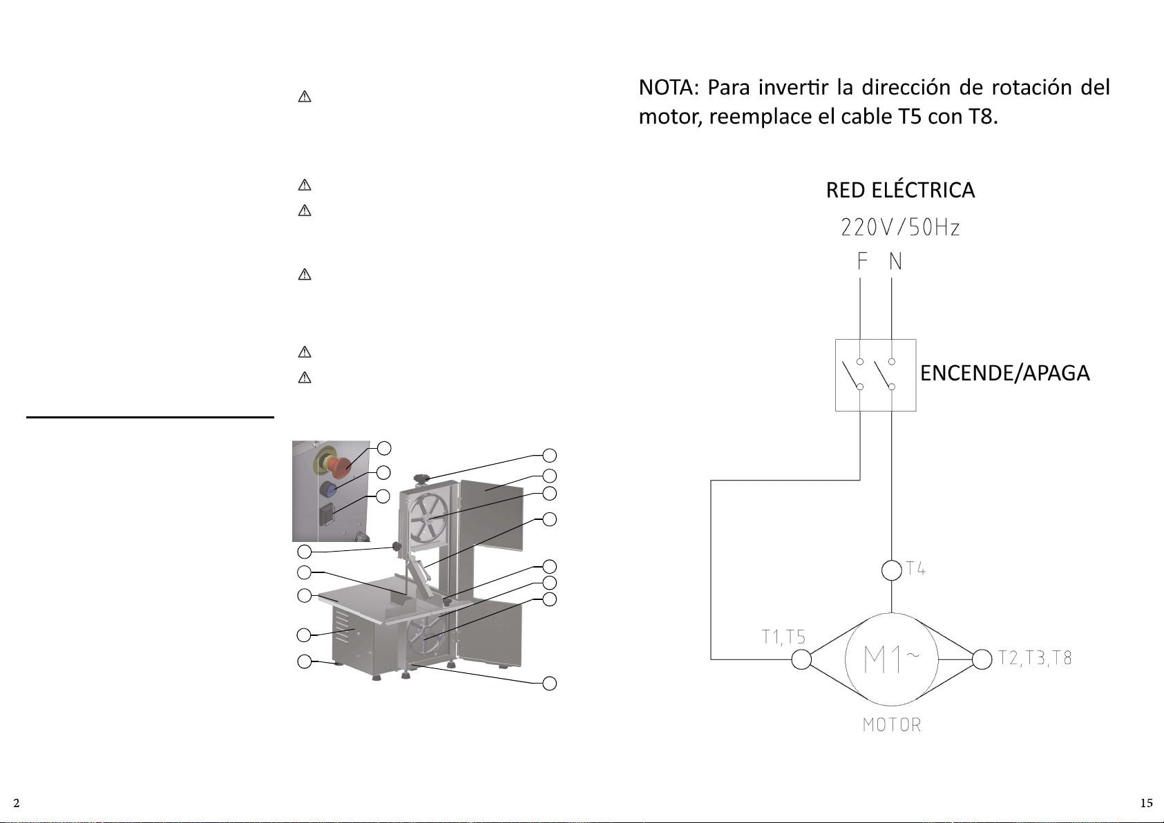
Picture 01
16
15
14
13
12
11
10
09
01 – Blade Tension Calibrang Handle
02 – Door
03 – Upper Wheel
04 – Frontal Protecon
05 – Cung Regulator
06 – Inferior Wheel
07 – Stamp
08 – Safety Sensor
09 – Foot
10 – Motor Housing
11 – Fixed Table
12 – Blade
13 – Blade Guide
14 – ON/OFF Switch
15 – Reset Switch
16 – Emergency Buon
01
02
03
04
05
06
07
08
NOTA: Para inverr la dirección de rotación del
motor, reemplace el cable T5 con T8.
RED ELÉCTRICA
ENCENDE/APAGA
Page 3
NOTA: Para inverr la dirección de rotación del
motor, reemplace el cable T5 con T8.
RED ELÉCTRICA
ENCENDE/APAGA
CHARACTERISTICS UNIT SB SBL
Voltage V 110 / 220 110 / 220
Frequency Hz 60 60
Motor Power CV 0,75 0,75
Height mm 895 895
Width mm 530 530
Depth mm 520 520
Net Weight kg 37,4 37,4
Gross Weight kg 54,6 54,6
Max Cung Height mm 200 200
Max Cung Width mm 170 170
3.INSTALLATION AND PRE-OPERATION
3.1 Posioning
Your equipment must be posioned and leveled on a dry
and firm surface, in an area of 855 mm of length and 650
mm of width.
3.2 Electrical Installaon
The plug has 3 pins, one of them is the ground wire. It is
mandatory that all 3 pins be connected to the power supply
before the equipment is turned on.
3.3 Pre-Operaon
Before turning on the equipment, clean all the componentes
that will be in contact with the product with water and
neutral detergent. (See the item 5 CLEANING).
4. OPERATION
4.1 Starng the equipment
To start the equipment follow the instrucons below:
1 - Make sure that all the protecons and the door are
correctly closed.
2 - Switch on the equipment to the power grid through the
outlet;
3 - Press and release the ON buon Nº 14 (Pic. 01).
4.2 Operaonal Procedures
4.2.1 Door
The door Nº 02 (Pic. 01) shall be closed as long as the
equipment is in use.
4.2.2 Blade
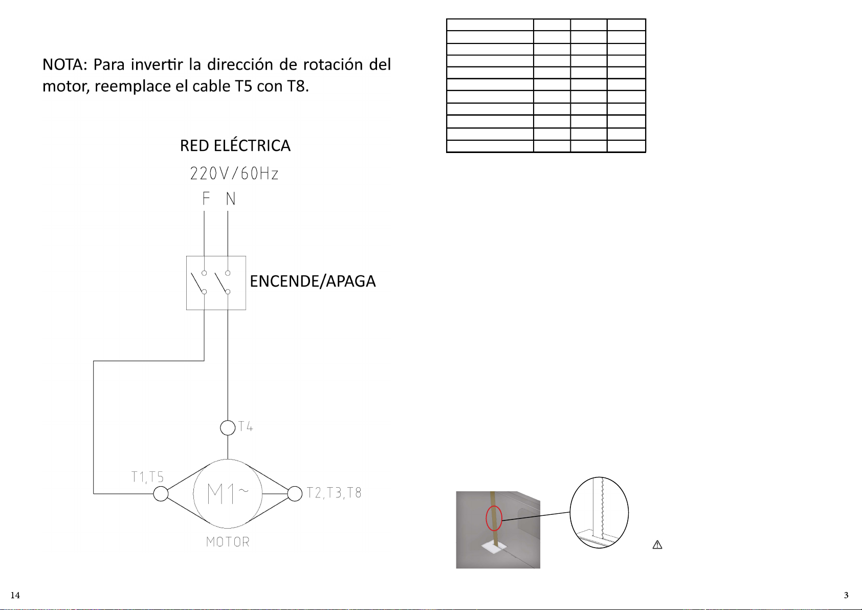
The Blade must be installed with its teeth turned to the front
of the saw, with its top turned down.
To regulate (stretch) the Blade Nº 12 (Pic. 01) turn the Blade
Tension Calibrang Handle Nº 01 (Pic. 01) unl the end.
4.2.3 Cung Regulator
To be able to get cuts with the same thickness adjust the
Cung Regulator Nº 05 (Pic.01) as you wish. To do so, turn
the Cung Regulator Handle on counter clockwise unl
it looses, so posion the Cung Regulator to the desired
thickness and press it turning the Handle to clockwise.
4.2.4 Blade Guide
With the aplliance turn the Handle Nº 13 (Pic. 01) in on
counterclockwise unl it looses the Blade Guide. Adjust
the Blade Guide unl the thickness desired is achieved and
press the Handle No. 13 (Pic. 01).
4.2.5 Lower Wheel
The Lower Wheel No. 06 (Pic. 01) is assembled in the inferior
bearing and fixed by the Scrap Nº 07, this scrap must always
be posioned in the sha groove.
4.2.6 Upper Wheel
The Upper Wheel No. 03 (Pic.01) has in its structure the
sha and the bearing.
4.2.7 Control panel
The control panel is located on the right side of the
equipment and has 01 ON/OFF Switch No. 14 (Pic. 01), 01
Reset Buon No. 15 (Pic. 01) and 01 Emergency Buon No.
16 (Pic. 01). To turn on the machine, proceed as described
in item 4.1.
Before turning on the equipment
Put the product to be cut on the Fixed Table Nº 11 (Pic. 01).
Regulate the thickness of the slices adjusng the Cung
Regulator Nº 05 (Pic. 01).
Li the Frontal Protecon No. 04 (Pic. 01) placing it on the
product to be cut.
Adjust the Blade Guide No. 13 (Pic. 01) to no more than the
height of the product to be cut.
Stay in front of the machine to have a front sight of the
Blade.
Turning on the equipment
To turn on the appliance, press the “I” buon on the ON/
OFF Switch Nº 13 (Pic. 01).
Catch the product with the le hand and the Frontal
Protecon Nº 04 with the right hand. Push the product
against the Blade cung it at constant speed.
Aer finishing the whole slice remove it with the right hand.
The slice shall ALWAYS be removed behind the Blade to
avoid the hand to contact the Blade.
Place the slices upon the Fixed Table # 11 (Pic. 01).
Bring back the product to the front side of the machine and
repeat the above steps unl to have finished to cut all the
product.
Aer the end of the last slice turn the ON/OFF Switch to the
posion “O” (OFF) No. 14 (Pic 01).
The slice shall ALWAYS be removed behind the Blade to
avoid the hand to contact the Blade.
Page 4
5. CLEANING
When the equipment must go through a complete
cleaning and sanizaon process:
- Before to be used first me;
- Aer every day end of operaons;
- When the saw is not going to be used for a long period.
- Before to start operaon aer a long period it has not
been used.
Some components may be removed to clean.
Follow below instrucons to remove the above menoned
components:
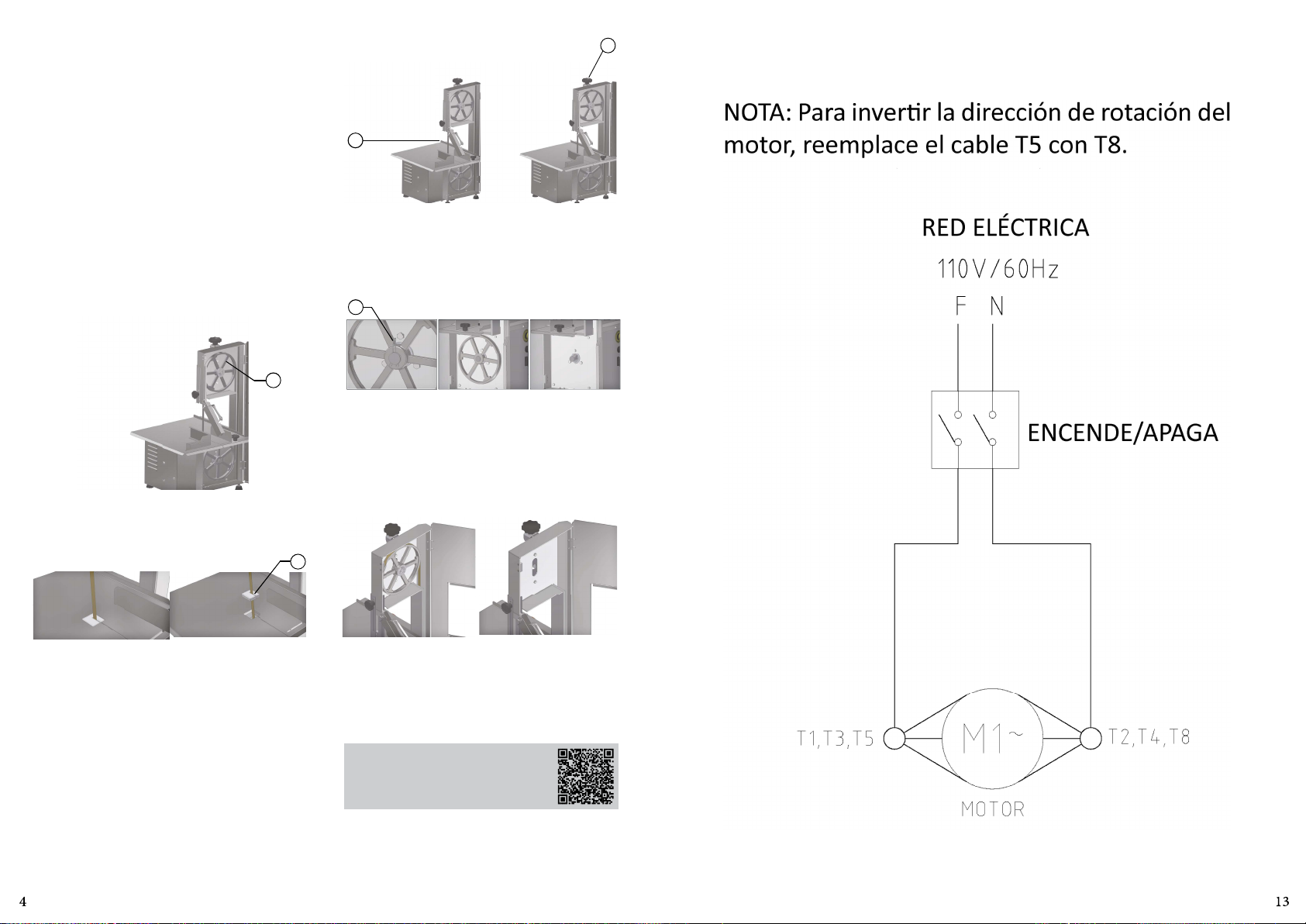
Door
Open the Door Nº 01 (Fig. 03) turning it to the right.
Picture 03
01
Picture 05
02
Lower Wheel
Remove the Sha No. 01 (Pic. 06), grab strongly the Lower
Wheel and pull it towards the front of the machine unl its
complete removal.
Picture 06
01
Upper Wheel
Aer removing the Blade grab strongly the Upper Wheel
No. 01 (Pic. 07), then li it and pull it to the front side of the
machine.
01
8. DIAGRAMAS ELÉCTRICOS
NOTA: Para inverr la dirección de rotación del
motor, reemplace el cable T5 con T8.
RED ELÉCTRICA
ENCENDE/APAGA
Fixed Table Block
Remove the Fixed Table Block #01 (Pic. 04) just liing it, see
picture 04.
Picture 04
Blade
Turn the Blade Tension Regulator Handle # 01 (Pic. 05)
counter clockwise to get the Blade # 02 (Pic. 05) free to be
removed.
01
Picture 07
Use a clean cloth or a so brush to remove residues.
Wash, sanize, rinse and dry all the components.
Assemble back all the components following the inverse
path, and make sure all the components are correctly in
place.
Use Your QR Code Reader to access more
informaon regarding the cares needed
when handling stainless Steel.
Page 5
6. MANTENIMIENTO
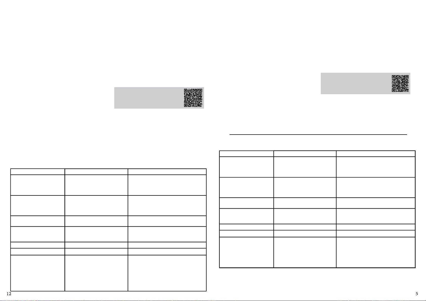
El Mantenimiento debe ser considerado como un conjunto
de procedimientos para ofrecer perfecta condición de
funcionamiento del equipamiento, aumentando la vida úl
y seguridad de uso del mismo.
* Limpieza – Verificar item 5 Limpieza de este manual.
* Cables – Controlar si los cables están en buen estado, sin
ningún daño y si todos los terminales eléctricos están bien
y sin oxidación.
* Verifique Llave ON/OFF, Llave reset, circuitos electrónicos,
para que todos estos componentes estén funcionando
correctamente y que el uso del equipo sea regular sin
inconvenientes.
* Instalación – Verifique la instalación de su equipamientos
el item 2 Instalación y Pre Operación de este manual.
1 - Itens a verificar y ejecutar mensualmente:
• Verificar la instalación eléctrica del local;
• Medir a tensión de la toma de corriente eléctrica;
• Medir la corriente de funcionamiento y comparar con la
corriente nominal;
• Verificar las conexiones de los terminales eléctricos del
equipamiento para evitar posibles fallos de contacto;
• Verificar posible desgaste o juego en el eje del motor
eléctrico;
Verificar los hilos de los cables eléctricos en cuanto a
señales de sobrecalentamiento, aislamiento dañado o
avería mecánica.
2 - Itens a verificar y executar a cada 3 meses:
• Verificar las partes eléctricas como Llave ON/OFF, botón
de emergencia, tecla reset y circuitos electrónicos cuanto
a señales de sobrecalentamiento, aislamiento dañado o
avería mecánica.
•Verificar posible juego en los cojinetes y rodamientos.
•Verificar retenes, o’rings, v’rings y otros sellos.
•Verifique el apriete de todos los tornillos y tuercas para
evitar posibles daños al equipo.
Pase el lector de QR Code para obtener
informaciones sobre seguridad y
mantenimiento.
7. RESOLUCIÓN DE PROBLEMAS
PROBLEMAS CAUSAS SOLUCIONES
- Falta de energia eléctrica;
- La maquina no se prender.
- La maquina se prende, pero
cuando el producto entra en
contacto con la Hoja, la misma
para o gira en baja rotación.
- Olor de quemado o humo;
- La hoja se rompe a menudo.
- Cabo electrico dañado. - Problema durante el transporte. - Llame el Servicio Técnico.
- Ruidos anormales. - Rodamiento dañado. - Llame el Servicio Técnico.
- Dificuldad en el corte del
producto.
- Problema con el circuito interno o
externo de la maquina.
- Correa panando;
- Problemas con el motor.
- Problema con el circuito Interno o
externo de la maquina.
- Suciedad en la hoja o el volante;
- Volante dañado.
- Suciedad en lsa hoja o en el Volante
- Hoja con mala tensión
- La hoja no está centrada con los
volantes;
- Hoja desafilada.
- Averigue si hay energia eléctrica;
- Llame el Servicio Técnico.
- Ajuste a tensão da lâmina, veja o item 4.2.3;
- Llame el Servicio Técnico.
- Llame el Servicio Técnico.
- Limpe, veja o item 5 LIMPEZA.
- Llame el Servicio Técnico.
- Hacer la limpieza de acuerdo con ítem 5;
- Ajuste a tensão da lâmina, veja o item 4.2.3;
- Llame el Servicio Técnico.
- Cambie la Hoja.
6. MAINTENANCE
Maintenance must be considered a set of procedures
with the purpose to keep the equipment best operang
condions, therefore increasing the equipment life and
safety.
* Cleaning – Check item 5 CLEANING.
* Wiring - Check all wires regarding deteriorate condions
as well as all electric contacts (terminals) regarding
ghtening and corrosion.
* Contacts – ON/OFF switch, emergency buon, reset
buon, electronic circuits, etc., check the equipment in
order to assure that all components are correctly working
and the equipment operaon is normal.
* Installaon – make sure the installaon followed item
3 instrucons.
* Life span: 50.000 cycles as per test standard.
1 – Each month check:
- Check the electrical installaon;
- Measure the voltage at the socket ;
- Measure the working current and match it with the
nominal current;
- Check the ghtening of all electric terminals to avoid bad
contacts.
- Check electric motor sha clearance;
- Check the wiring for overheang, insulaon failures and
mechanical damages.
2 – Each three month checks:
- Check electrical components such as ON/OFF switch,
emergency buon, reset buon, electronic electric circuits,
overeang, insulaon failings, or mechanical damages
- Check bearings clearances;
- Check retainers, O’rings, V’rings and other seals.
- Check that all screws and nuts are ght to avoid possible
damage to the equipment.
Use Your QR Code Reader to access
more informaon regarding safety and
maintenance.
7. PROBLEMS RESOLUTION
PROBLEMS CAUSES SOLUTIONS
- The equipment does not
switch on.
- Machine switch on but when
product touches the blade it
stops or runs slowly.
- Smoke or burn smell.
- Blade breaks frequently.
- Damaged Cord. - Problem during transportaon. - Call Technical Assistance.
- Unusual noises. - Problems with bearings. - Call Technical Assistance.
- Difficules to cut the product.
- Lack of Power;
- Problem with the internal or
external electric circuits.
- Belt slipping on pulleys.
- Damaged Motor.
- Problem with the internal or
external electric circuits.
- Dirty Blade or Wheel.
- Wheel Damaged.
- Dirty blade or wheels.
- Blade with wrong tension;
- Blade is not on wheels center;
- Blunt blade.
- Check if there is electric power.
- Call Technical Assistance.
- Adjust the blade tension, see item 4.2.3;
- Call Technical Assistance.
- Call Technical Assistance.
- Clean, see the item 5 CLEANING.
- Call Technical Assistance.
- Clean,see the item 5 CLEANING;
- Adjust the blade tension, see item 4.2.3;
- Call Technical Assistance.
- Change the Blade.
Page 6
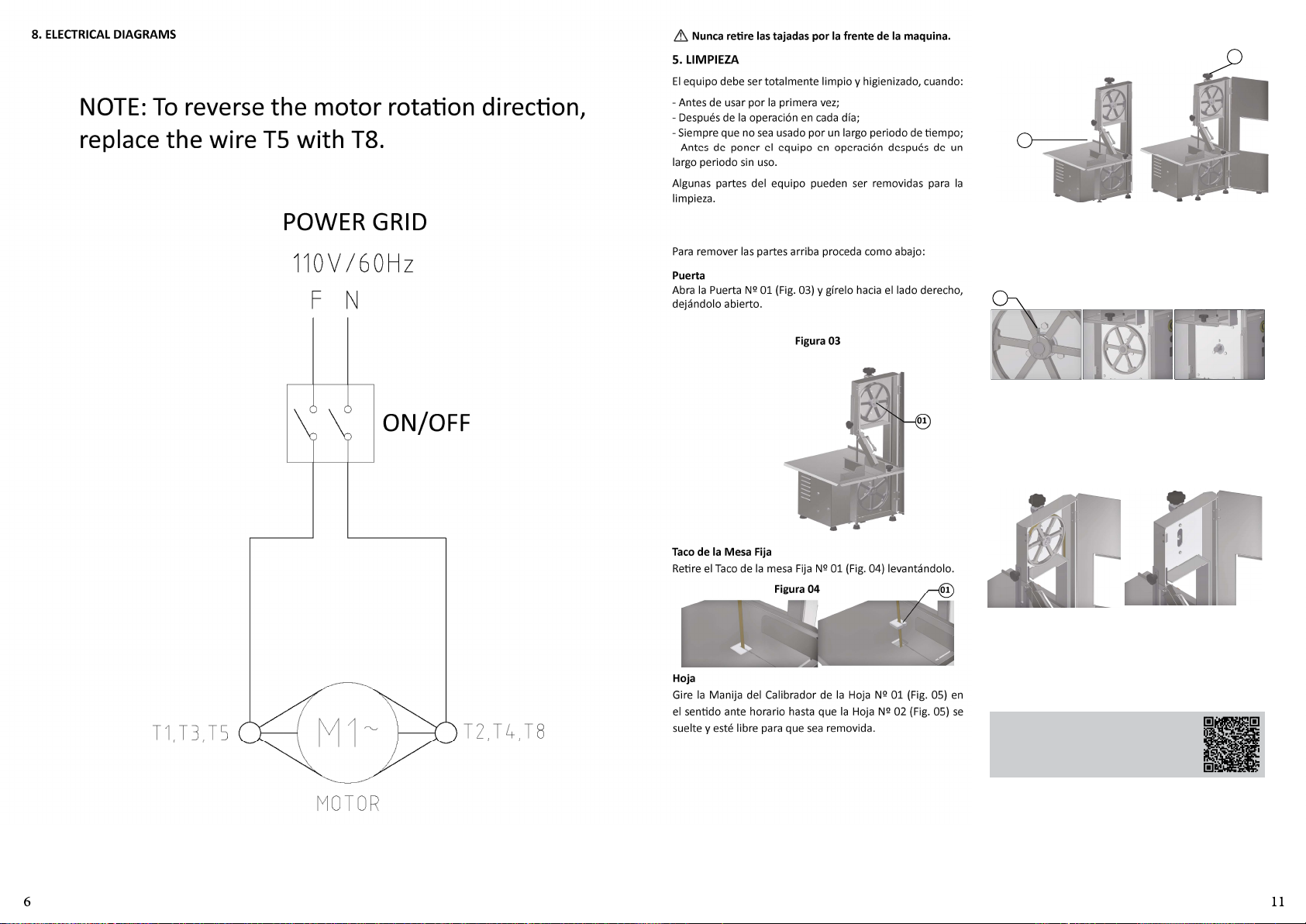
8. ELECTRICAL DIAGRAMS
NOTE: To reverse the motor rotaon direcon,
replace the wire T5 with T8.
Nunca rere las tajadas por la frente de la maquina.
5. LIMPIEZA
El equipo debe ser totalmente limpio y higienizado, cuando:
- Antes de usar por la primera vez;
- Después de la operación en cada día;
- Siempre que no sea usado por un largo periodo de empo;
- Antes de poner el equipo en operación después de un
largo periodo sin uso.
Algunas partes del equipo pueden ser removidas para la
limpieza.
Figura 05
01
02
POWER GRID
ON/OFF
Para remover las partes arriba proceda como abajo:
Puerta
Abra la Puerta Nº 01 (Fig. 03) y gírelo hacia el lado derecho,
dejándolo abierto.
Figura 03
01
Taco de la Mesa Fija
Rere el Taco de la mesa Fija Nº 01 (Fig. 04) levantándolo.
01Figura 04
Hoja
Gire la Manija del Calibrador de la Hoja Nº 01 (Fig. 05) en
el sendo ante horario hasta que la Hoja Nº 02 (Fig. 05) se
suelte y esté libre para que sea removida.
Volante Inferior
Rere la Presilla N° 01 (Fig. 06), agarre firmemente el
Volante Inferior y ơrelo para la frente de la maquina, vea
la Figura 06.
Figura 06
01
Volante Superior
Después de haber rerado la Hoja agarre firmemente el
Volante Superior N° 01 (Fig. 07), empújelo para arriba y en
seguida ơrelo para la frente de la maquina.
Figura 07
Use un paño limpio ó un cepillo blando para remover
residuos impregnados.
Lave, higienice, enjuague y seque todas las partes.
Monte de vuelta todos los componentes de la maquina en
el orden inverso al del desmontaje , averiguando que todos
estén correctamente montados.
Pase el lector de QR Code para obtener
informaciones sobre cuidados con los
aceros inoxidables.
Page 7
CARACTERÍSTICAS UNIDAD SB SBL
Tensión V 110 / 220 110 / 220
Frecuencia Hz 60 60
Potencia del Motor CV 0,75 0,75
Altura mm 895 895
Ancho mm 530 530
Profundidad mm 520 520
Peso Neto kg 37,4 37,4
Peso Bruto kg 54,6 54,6
Altura Max. de Corte mm 200 200
Ancho Max. de Corte mm 170 170
3.INSTALACIÓN Y PRE-OPERACIÓN
3.1 Posicionamiento
Su equipamiento deberá estar posicionado y nivelado arriba
de una superficie seca, en un área de 855 mm de largo y 650
mm de ancho.
3.2 Instalación Electrica
El enchufe del cable de alimentación eléctrica posee tres
pernos el perno central es la erra. Los tres pernos deben
estar conectados antes de prender la maquina.
3.3 Pre-Operación
Antes de usar el equipo se debe lavar todas las partes que
entren en contacto con el producto a ser procesado con
agua y jabón neutro (vea ítem 5 LIMPIEZA).
4. OPERACIÓN
4.1 Accionamento
Para prender el equipo siga las instrucciones abajo:
1 - Verifique si TODAS las protecciones están debidamente
posicionadas y la puerta cerrada.
2 - Conecte el equipo a la red eléctrica;
3 - Presione la llave Prende/Apaga No. 14 (Fig 01) para la
posición “I” y la maquina se prende.
4.2 Procedimiento para la Operación
4.2.1 Puerta
La Puerta N°02 (Fig. 01) está conectada com Sensor de
Segurança que impede a máquina de ser acionada com a
Porta aberta, portanto para a máquina funcionar a Porta
deve permanecer fechada enquanto esver em uso.
4.2.2 Hoja
La hoja debe ser instalada con los dientes vueltos para la
frente de la maquina y con las puntas para bajo.
Para calibrar (esrar) la Hoja gire la Manija del Calibrador
de la Hoja No.01 (Fig.01) en el sendo HORARIO hasta que
pare.
4.2.3 Regulador de Corte
Para realizar varios cortes de la misma espesura, ajuste
el Regulador de Corte Nº 05 (Fig. 01) como deseado.
Para hacer eso gire la Manija del Regulador de Corte en
el sendo ante horario liberándolo, después lleve hasta
la espesura deseada y apriete firmemente la Manija del
regulador girándola en el sendo horario.
4.2.4 Guía de la Hoja
Con el equipo apagado gire la Manija Nº 13 (Fig. 01) en el
sendo ante horario para libertar la Guía de la Hoja. Ajuste
la altura de la Guía de la Hoja para la altura, no mas, de la
pieza a ser cortada, después apriete la Manija Nº 13 (Fig.01).
4.2.5 Volante Inferior
El volante inferior Nº 06 (Fig. 01) está montado sobre el
eje del cojinete inferior y preso por la presilla Nº 07, esta
presilha deverá estar sempre posicionada na ranhura do
eixo.
4.2.6 Volante Superior
El Volante Superior Nº 03 (Fig. 01) incorpora en su estructura
el eje y los rodamientos.
4.2.7 Panel de Control
El panel de control está ubicado en el lado derecho del
equipo y ene 01 Interruptor de Encendido / Apagado No.
14 (Fig.01), 01 Botón de Reinicio No. 15 (Fig.01) y 01 Botón
de Emergencia No. 16 (Fig.01). Para encender la máquina,
proceda como se describe en el ítem 4.1.
Antes de prender la maquina
Coloque el producto a ser cortado sobre la Mesa Fixa Nº
11 (Fig. 01).
Elija la espesura de la tajada a ser cortada y ajuste el
Regulador de Corte No. 05 (Fig. 01).
Levante la Protección Frontal No. 04 (Fig. 01) colocándola
sobre el producto a cortar.
Ajuste el Guia de la Hoja Nº 13 (Fig. 01) para que su zona de
el corte sea la altura de la pieza a ser cortada, no mas.
Colóquese en frente a la maquina para poder mirar de
frente la Hoja.
Acionar o equipamento
Para prender la maquina Gire la Llave Prende/Apaga No.14
(Fig. 01) para la posición “I”.
Agarre el producto a cortar con la mano izquierda y la
empuñadura de Protección Frontal nº 04 (Fig. 01) con
la mano derecha. Deslice el producto contra la Cuchilla,
cortándolo a velocidad constante.
Después de cortar la tajada reơrela con la mano derecha.
La tajada deberá ser removida SIEMPRE por atrás de la Hoja
para evitar el contacto de la mano con la Hoja.
Coloque las tajadas sobre la Mesa Fija Nº 11.
Regrese el producto al frente del equipo y repita el proceso
hasta que se haya cortado todo el producto.
Al terminar la ulma tajada apague la maquina presionando
la Llave Prende/Apaga en la posición “O”.
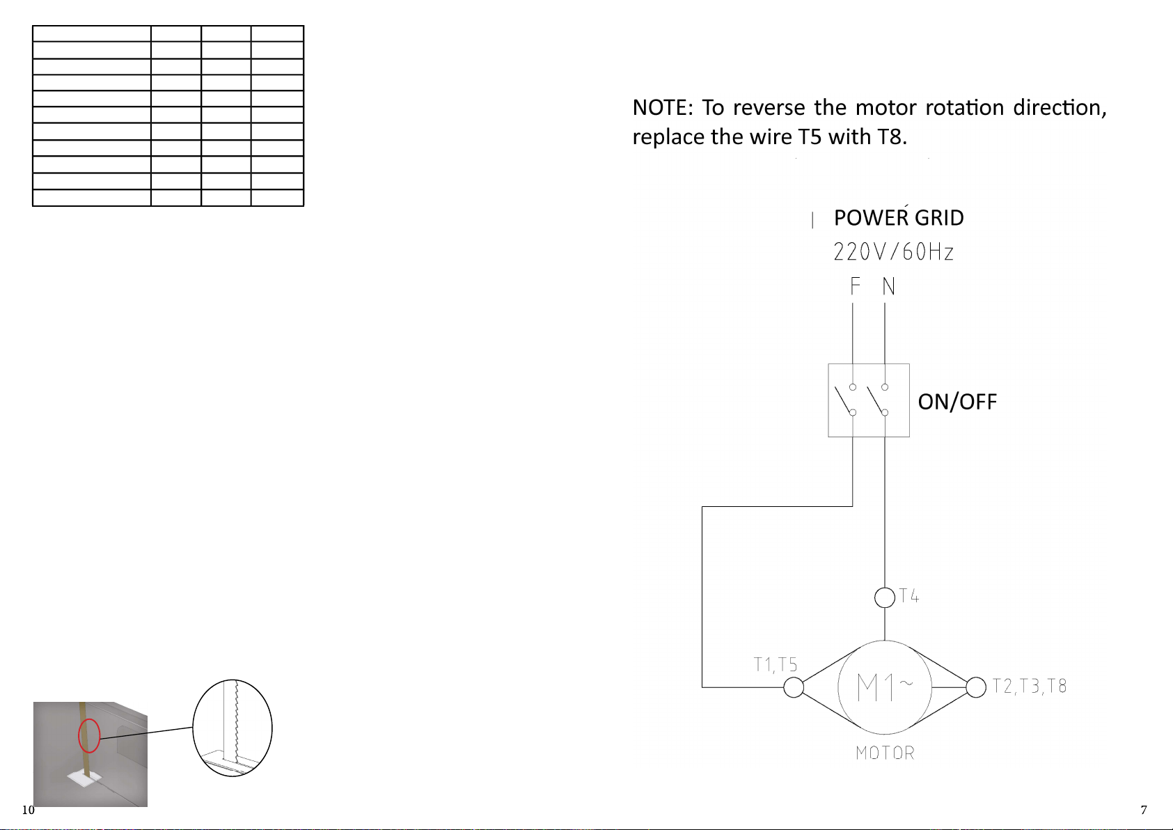
NOTE: To reverse the motor rotaon direcon,
replace the wire T5 with T8.
POWER GRID
ON/OFF
Page 8
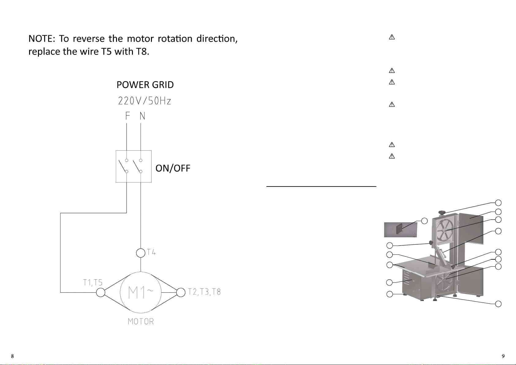
NOTE: To reverse the motor rotaon direcon,
replace the wire T5 with T8.
POWER GRID
ON/OFF
INDICE
1. INTRODUCCIÓN .............................9
1.1 Seguridad ............................................... 9
2. COMPONENTES PRINCIPALES Y
CARACTERÍSTICAS TÉCNICAS ..............9
3.INSTALACCIÓN Y PRE-OPERACIÓN ...10
3.1 Posicioniamento ..................................... 10
3.2 Instalacción Eléctrica .............................. 10
3.3 Pre-Operación ......................................... 10
4. OPERACIÓN ...................................10
4.1 Acionamiento ......................................... 10
4.2 Procedimientos para Operación .............. 10
4.3 Sistema de Seguridad .............................. 10
5. LIMPIEZA .......................................11
6. MANTENIMIENTO ..........................12
7. RESOLUCIÓN DE PROBLEMAS ........12
8. DIAGRAMAS ELÉCTRICOS ...............13
eléctrica del local sean adecuadas para el uso de este
equipo y que el equipo está conectado al cable erra.
1.1.7 Nunca regule la Guia de la Hoja ni el Regulador de
Corte con la maquina en movimiento.
Este equipamiento não se desna a la ulización
por personas (inclusive niños) con capacidad sicas,
sensoriales o mentales reducidas, o por persona
con falta de experiencia y concoimiento, salvo si
hubiera recibido la capacitación adecuada o esté bajo la
supervision del encargado por su seguridad.
Recomendamos que se vigile a los niños para no
permirles jugar con la máquina.
Desconecte el equipamento de la red eléctrica
quando: no esté en uso, antes de limpiarlo, al sacar o
colocar accesorios, antes del servicio de mantenimiento o
antes de cualquier po de serviçio.
No use el equipo cuando tenga el cable o el enchufe
damnificado. No deje que el cable de alimentación se
quede en el borde de una mesa, o que toque superficies
calientes. Si el enchufe estuviera damnificado, sustuya el
cable damnificado por otro que respete lasespecificaciones
técnicas y de seguridad. Esta sustución deberá ser hecha
por un profesional calificado.
En caso de emergencia rere el enchufe de la toma de
energía eléctrica.
Nunca use chorros de agua directamente sobre el
equipo.
2. COMPONENTES PRINCIPALES Y CARACTERÍSTICAS
TÉCNICAS
1. INTRODUCCIÓN
Este equipo fue desarrollado para uso en cocinas comerciales,
por ejemplo restaurantes, cafeterías, hospitales, panaderías,
carnicerías ó similares.
El uso de este equipo no se recomienda cuando:
- El procedimiento de producción sea connuado en escala
industrial;
- El local de trabajo tenga un ambiente con atmósfera
corrosiva, explosiva, contaminada con vapor de agua ó gas.
1.1 Seguridad
Las instrucciones abajo deberán ser siguidas para evitar
accidentes, el incumplimiento puede causar lesiones graves:
1.1.1 Nunca ulice este equipamiento con ropas o piés
mojados o en superície humeda o molhada, no sumergir
el equipo en agua ni bajo el grifo y no ulice manguera de
agua a presión sobre el equipamiento.
1.1.2 Cuando el equipo se haya caído, estuviera damnificado
de alguna manera ó no funcione llévelo hasta una Asistencia
Técnica.
1.1.3 La ulización de accesórios no recomendados por el
fabricante pueden ocasionar lesions en el usuario.
1.1.4 Mantenga las manos y cualquer utensílio alejados de
las partes en movimientos del equipo.
1.1.5 Nunca use ropas con mangas largas, principalmente en
la muñeca.
1.1.6 Cerfique que la tension del equipamiento y de red
Figura 01
14
13
12
11
10
09
01 – Maníja del Calibrador de la Hoja
02 – Puerta
03 – Volante Superior
04 – Proteção Frontal
05 – Regulador de Corte
06 – Volante Inferior
07 – Presilha do Volante
08 – Sensor de Segurança
09 – Pie
10 – Gabinete
11 – Mesa Fija
12 – Hoja
13 – Guia de la Hoja
14 – Llave Prende/Apaga
01
02
03
04
05
06
07
08
 Loading...