


GSM/GPS
Car Tracking Alarm
USER MANUAL
Ver: 1.16

CONTENTS
Ver: CAT5: HW-V1.3 SW-V1.16 EN
INTRODUCTION---------------------------------------------------------------------------------2
Functions and Features----------------------------------------------------------------------2
Technical Specification-----------------------------------------------------------------------3
Safety Instructions-----------------------------------------------------------------------------3
ACCESSORIES----------------------------------------------------------------------------------4
User Necessaries----------------------------------------------------------------------------4
Basic Components---------------------------------------------------------------------------4
INSTALLATION-----------------------------------------------------------------------------------5
Installation Process---------------------------------------------------------------------------6
Instructions before Use----------------------------------------------------------------------8
OPERATIONS-------------------------------------------------------------------------------------9
SMS OPERATIONS---------------------------------------------------------------------------9
VOICE OPERATIONS------------------------------------------------------------------------9
1. Alarm Setup-----------------------------------------------------------------------------10
2. Basic Operations-----------------------------------------------------------------------10
3. Query-------------------------------------------------------------------------------------16
4. Other Functions------------------------------------------------------------------------17
ALERT REPORT-------------------------------------------------------------------------------18
1. Alert Type---------------------------------------------------------------------------------- 18
2. Alert Report Mode -----------------------------------------------------------------------18
3. Alert Report--------------------------------------------------------------------------------18
4. Alert Management------------------------------------------------------------------------20
APPENDIX---------------------------------------------------------------------------------------21
1. Problems and Solutions------------------------------------------------------21
2. Alert SMS Format-------------------------------------------------------------------------21
3. Operation SMS Commands ---------------------------------------------------------- 22
4. Remote Control RF Code Setup------------------------------------------------------22
- 1 -

INTRODUCTION
Functions and Features
Application:
Protect all type of cars, trucks, taxi, jeeps as well as other automobiles.
Position and tracking
◆ Dual location:
Locate the vehicle through both GPS positioning and GSM base station
◆ Query location address by mobile-phone or on computer.
◆ Real-time or pre-set time tracking by SMS/GPRS;
◆ Global tracking : Web-based center with Google-earth or Google-Map support
and clear satellite image view
Anti-theft functions
◆ Door open/ Acc on/car vibration/car moving /power down Alert
◆ Alert will be reported to the preset phone by auto-dial and SMS.
◆ Switch on/off the engine remotely by phone/SMS
Anti-robbery functions
◆ Built-in Emergency Alert(SOS) button
◆ Monitor the sound in the car remotely
◆ Stop the engine or cut off oil supply remotely
Simple Operation
◆ Voice system and SMS remote control
◆ Lock the door automatically when arming and unlock when disarming.
The user can choose between unlock or dis-unlock when ACC switches off.
Other useful functions
◆ With backup battery:
After Power Off Alert, the back-up battery will supply power.
◆ Auto-arming function: choose on/off.
◆ The sensitivity of the vibration sensor can be adjusted
◆ Lights flash and sound reminder
- 2 -

Technical Specification
> GSM Working Frequency:850(Optional) /900 /1800 /1900MHz
> GPS(SiRFstarIII chipset) : Frequency:L1, 1575.42 MHz.
Minimum signal tracked: -159dBm
> Temperature: Working Temp -20℃ ~ +60℃
> Humidity: 20—95%
> Cable type
GSM Antenna: Gain: 3dBi Cable Length: 3-5meters Connector: SMA
Portable antenna: Gain: 2dBi Height: 5cm Connector: SMA
> GPS Antenna: Voltage: 3V Cable Length: 3-5 meters Connector: SMA
> Remote control: Working frequency: 315Hz/433MHz.
Code: 1527/2240 study code
Working Voltage: 12V (27A 12V dry battery)
Control Distance: 20-100M
> Mainframe Power supply: 12 or 24V DC
> Backup battery: Poly-Li battery, 600mAh 3.7V
> Mainframe Dimension: 125x108x26mm
> Weight: G.W.:1.45Kg/set (including accessories)
Package dimension:285*250*90mm
Export carton dimension:520*295*480mm(10PCS)
Safety Instructions
> Please do not use the device in the areas where wireless device are
prohibited.
> Please use the accessories in the package, such as the antennas and relay.
Don’t use accessories produced by other manufacturers or different models.
We will not be held responsible for any problems caused by using accessories
of other manufacturers.
> Please install the system by professional.
- 3 -
ACCESSORIES
User Necessaries
1. 1-3 mobile phones (Note: with SMS functions.)
2. A GSM SIM card for the devices(
SMS/GPRS functions and enough balance)
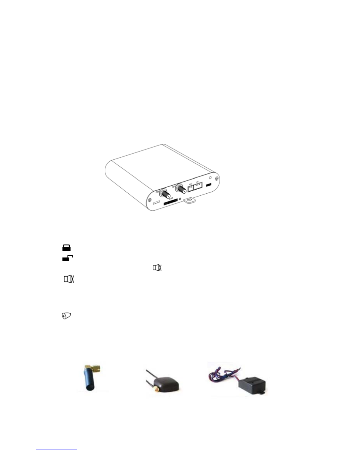
Basic components
1. Main Unit
2. Remote control: Maximum 3pcs
Arm/lock the car, when arming the fore-lights flash and siren rings once
Unarm/ unlock the car. when disarming the fore-lights flash and siren
rings twice; if arming by
silent arming key, the siren will not ring.
Silent arm key. Press it, the device switches into armed mode without
siren ringing.
On silent arm mode, if the alert is tirgged, the siren will not ring.
Search for the car: activate car lights and siren to search for car. the siren
will ring for 3 beeps.
3. GSM antenna 4. GPS antenna 5. Vibration sensor
(Adjustable sensitivity)
- 4 -

6.Microphone (Monitor) 7. Siren 8. 20 PIN connection wire
9. LED indicator 10. Stop Relay 11. SOS button
INSTALLATION
Panels & Sockets
GSM: GSM Antenna GPS: GPS Antenna RF: RF-Antenna
USB: load-down data SIM: SIM Card Slot MIC: Monitor
TEST: Socket: for factory use only BAT: Backup Battery Switch
- 5 -
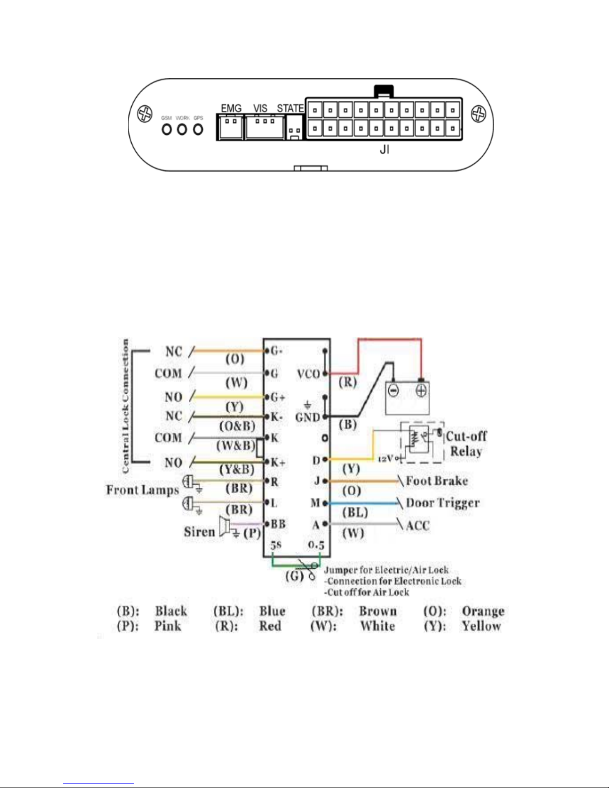
EMG: SOS Button VIS: Vibration Sensor STATE: LED Light
J1: 20PIN Connection wire socket
Installation Process
1. Connect the Central Lock to 20 PIN connection w ire
1.1 Central lock : Choose installation of different central lock and
connect to G-, G, G+ and K-, K, K+ of the 20pin
controlling wires
- 6 -

+12V
Fig2: Positive Trigger
Fig1: Negative Trigger
+12V
Fig3: Negative & Positive Trigger
1.2 Connect to detecting signal
(1) J---Foot brake wire
(2) M---Door trigger wire
(3) A---ACC (Igniting switch)
1.3 Connect to controlling signal
(1) R,L ( 1PIN each)---Left/Right lamps wires
(2) BB ---Siren
(3) D---------the yellow wire of Relay;
12V+ --- the white wire of the relay.
Cut the On/Start/Oil line --- connecting two green wires in
Note: Three connection mode :( after sending “stop”)
1. Into start line: after turning off engine, can’t start again.
2. Into ON line: engine turning off right-away
3. Into OIL line: engine turning off after 1-3mins.
1.4 Power supply: VCO and GND --- Power supply
Note: Green wire---- (spare)
- 7 -

2. SIM Card: press the yellow button to open
the slot and put the sim in.
3. GSM---GSM Antenna Installation
4. GPS--- GPS Antenna Installation
5. MIC--- Microphone (monitor) installation
6. EMG--- Connect SOS button wire
7. VIS--- Connect Vibrator sensor
8. STATE---Connect the LED wire
9. Plug the 20PIN into J1, the “WORK” light starts flashing.
10. Slide the battery switch to “ON” position
11. Fix: After installation, check installation of all wires, fix them firmly.
Instructions before Use
1. LED indication:
After installation and power on, the system shows the status:
GSM LED: Flashing fast: indicates that GSM have not registered
Flashing slowly: indicates that GSM works well.
GPS LED: It is on indicating that GPS signal is available.
WORK LED:It flashs to indicate work normally.
2. Factory default setting: Recipient: Non
User Password: 1234
Status: Unarmed
Time Zone: +/-0000
Shake Alert: On
Unlock while ACC turning off : On
Auto-arm: On
Power alert: On
Move Alert: Off
Over Speed Alert: Off
3. Battery: Auto-charge when it connects to power supply.
4. GSM/GPS ANT: Place the ANT in suitable area to get signal well.
- 8 -

OPERATIONS
SMS Operation:
User can setup, control the system and query the status of the car by
sending SMS command via any mobile-phone.
The pre-set recipients will receive the alert SMS and call.
SMS Format: *[User PASSWORD]*[COMMAND]#.
Note: > User Password is 4 digits or letters in SMS and is abbreviated to: UPWD
> Send commands by any mobile phone via UPWD
> the command can be capital or lower case letters
VOICE OPERATION: Dial the device; after 4 beeps, you can operate the
device by following the voice prompt.
Note:
The password of Voice operation is the same as in SMS operations.
Welcome to …
N
Sorry, password
denied…
Y
Password is
Power On/Off
Armed/Unarmed------
Q
uery about
your
vehicle status
Press 1
Press 3
Press 2
Modify your
password
Restore to
factory settings
Please input your new
4-digit password…
T
he password you
entered is: xxxx
Press pound (#)
Press not #
Press#
Password has
been changed!
key to confirm!
Factory settings
restored
Monitor the voices
in your vehic le
Return to the
Press 6
Press *
previous directory
Switch your CAT
into armed mode
Switch your CAT into
unarmed mode
Press 1
Press 2
Unarmed Mode
activated
Armed Mode
activated
De-energize and
stop the engine
Re-energize and start
The engine can be
started right now
The engine has
been turned off
the engine
A
larm Control
Press 3
Press 4
Press 5
Hang up to end
- 9 -

1. Alarm Setup
1.1 Set up recipient A, B and C
Send the SMS to the device: Set successfully, the reply SMS:
Change or Cancel recipients:re-set new recipients.
Note:
① A, B, C indicates the recipients A, B, C.
xxxxx…indicates the recipients’ mobile phone number. Max: 20 digits.
② “+country code” should be added when SMS format requires
SMS Format: + Country Code + mobile phone number.
③ Recipient number is blank if you do not set up it.
Exp:
Recipient A,C setup:*1234 *A+8613666504824*B*C+8613666502528#
(+86 refers to China code; 136xxxxxx refers to Recipients mobile number)
1.2 Set up Time-zone
Send the SMS to the device: Set successfully the reply SMS:
*UPWD*AXXXXXXX*BXXX
XXXXX*CXXXXXXXX#
Armed/Unarmed;A:XXXXX,
B:XXXXXXXX,C:XXXXXXX;
*UPWD*GMT+/-xxxx#
GMT+/-xxxx Setup OK!
Note: ‘+’ is east zone; ‘-’ is west zone
Exp:
East 8 zone (GMT+08:00), the SMS should be *1234*GMT+0800#
West 3:30 zone (GMT-3:30), the SMS should be *1111* GMT-0330#
2. Basic Operations
2.1 Arm the Device:
◆ On armed mode, the state LED is on.
◆ While arming, the doors are auto-locked.
A. Arm the system manually:
> Press ‘
’ key on the remote control, the siren sounds once.
- 10 -

> Press ‘ ’ key: the device switches into armed mode. But the
siren is turned off. if alert is triggered, the siren
will not ring.
B. Auto-Arm: If Auto-arm function on and system status is unarmed,
the door is closed and ACC off, the system will switch
to armed mode automatically after 2mins.
For convenience to operate, the auto-arm function
can be turned On/Off by SMS.
Auto-arm off:
Send the SMS:
SMS replies:
Auto-arm on:
Send the SMS: SMS replies:
Note: > On unarmed mode, if someone in the car with the door closed and ACC
off, the system will auto-arm.
> When auto-arm is valid, the vehicle accidental auto-armed at some place
of poor GSM signal, you may not open the door via SMS or phone voice.
C. Arm by SMS:
Send the SMS: SMS reply:
*UPWD*Aoff#
Auto-arm off !
*UPWD*Aon#
Auto-arm on !
*UPWD*S#
Armed;ACC:on/off;Door:close/open;LAC
:xxxxx;CID:xxxxx;Time:
XX-XX-XX XX:XX:XX
Speed:xxxkm/hS/Nxx.xxxx W/Exxx.xxxx
D. Arm by Voice Operations:Refer to: Voice Operations(page 9)
Note: > If door is opened, the system can be armed; then “Door open alert” will be
triggered.
> The doors are auto-locked when arming the system.
> On armed status, the engine can not be started.
- 11 -

2.2 Disarm the Device:
◆ On unarmed state, the state LED is off;
◆ While disarming, the doors are auto-unlocked.
A. Disarm manually:
Press ‘
’ key on the remote control, the device is disarmed.
The siren will sound twice.
B. Disarm by SMS:
Send the SMS: SMS replies:
*UPWD*C#
Unarmed;ACC:on/off;Door:close/open;LA
C:xxxxx;CID:xxxxx;Time:
XX-XX-XX XX:XX:XX
Speed:xxxkm/h S/Nxx.xxxx W/Exxx.xxxx
C. Disarm by Voice Operations ( Refer to: Voice Operations)
Note
:
> On Unarmed Mode, if the door is open, the R/L lamps light 5secs.
> If ACC-on, pressing the footbrake to lock the doors once every time
opening the car door.
2.3 Modify Password
A. By SMS:
Send the SMS to the device: Set up successfully, it replies:
*UPWD*Exxxx#
Password has been changed!
Note: xxxx refers to the new PASSWORD. It is composed of 4 ASCII codes.
Factory default: 1234.
B. By Voice Operations: Please refer to Voice Operations
2.4 Shake Alert ON/OFF
Off:
Send the SMS to the device: Set up successfully, it replies:
*UPWD*N#
Shake Alert Off!
- 12 -

On:
Send the SMS to the device: Set up successfully, it replies:
*UPWD*H#
Shake Alert On!
2.5 Unlock On/Off:
On ‘Unlock on’ state, while ACC is off, the door of the vehicle
auto-unlock;
On ‘Unlock off’ state, when ACC is off, the door of the vehicle
doesn’t unlock.
Off:
Send the SMS to the device: Set up successfully, it replies:
On:
Send the SMS to the device: Set up successfully, it replies:
2.6 Power Off Alert on Un armed On/Off:
Power Off alert is valid on armed state, But can choose Power Off
Alert On/Off on unarmed mode:
Off: ( Power off alert is valid only on armed status.)
Send the SMS to the device: Set up successfully, it replies:
On: ( Power off alert is valid at any time.)
Send the SMS to the device: Set up successfully, it replies:
*UPWD*UL0#
Auto Unlock Door Off!
*UPWD*UL1#
Auto Unlock Door On!
*UPWD*PW0#
Power Off Alert Valid
On Armed
*UPWD*PW1#
Power Off Alert on !
- 13 -

2.7 Immobilize / Relieve
2.7.1 STOP the car after sending co mmand
A. Enforced–off by SMS
Send the SMS to the device: Set up successfully, it replies:
Note: > After “stop” command valid, the On/Start/Fuel wire will be cut off.
> To restart your engine, you will have to Relieve 'STOP' command.
B. Immobilize by phone :( Refer to Voice Operation)
2.7.2 Delay to stop the car
Sending SMS: Set up successfully, it replies:
Note:
When the command is sent, the car will not stop. After engine off, can not be
restarted again; To restart your engine, you will have to send Re-energize
SMS command to the device.
2.7.3 Re-energize By SMS:
A. Send the SMS to the device: Set up successfully, it replies:
B. Relieve by phone: (Refer to Voice Operations)
2.8 Move Alert on/off :
On armed Mode, if the car moves over a certain range, the
device will send a ‘Move alert’ SMS to the recipients.
On:
Send the SMS to the device: Set up successfully, it replies:
*UPWD*STOP#
Engine will be turned off!
*UPWD*STOPD#
Engine will be turned off!
*UPWD*K#
Relieve 'STOP' & Unarmed!
*UPWD*MOVExxx# MOVExxx Alert On!
Note:
xxx : 300~999. It indicates that the alert range is a circle, the center of
which is the parking position and the radius is xxx meter.
- 14 -

Off:
Send the SMS to the device: Set up successfully, it replies:
2.9 Over Speed Alert On/Off
Over speed Alert: when this function is on, if the car drives over the
speed limit, alert SMS will be sent to recipient A.
On:
Send the SMS to the device: Set up successfully, it replies:
*UPWD*MOVE000#
MOVE Alert Off!
*UPWD*SPDxxx,SS#
Over Speedxxx Alert On!
Note: xxx: 020~999, min speed is 20Km/H; max speed is 999 Km/H.
If xxx is less than 020,“Over speed Alert” will not be triggered
ss: 01~99min, indicates the interval of speed detecting.
Off:
Send the SMS to the device: Set up successfully, it replies:
2.10 Resume to Factory Default
A. By SMS:
Send the SMS to the device: Set up successfully, it replies:
*UPWD*SPD000#
Over Speed Alert Off!
*UPWD*V#
Factory Default Restored!
B. By phone :( Please refer to Voice Operations)
Note: the command can not change the state of “power off alert”
2.11 Search for car
A. Press ‘ ’key on the remote controller. Your car light will flash and
the siren will ring seconds.
- 15 -

B. By SMS:
Send the SMS to the device:
*UPWD*T#
Note: After sending the command, the device will not reply SMS to you, the siren
will ring and your car lights will flash for seconds.
2.12 Wrong Message
◆ The password is wrong, the device will send the prompt SMS:
Key incorrect, Please confirm!
◆ When SMS command is invalid, you will receive the prompt SMS
prompt:
Invalid command, please confirm!
3. Query
3.1 Recipients Query
Send the SMS to the device: SMS reply:
3.2 Status Query
A. Status Query by SMS:
Send the SMS to the device: GPS is available, SMS replies:
*UPWD*Y#
Armed/Unarmed;A:XXXXXX,
B:XXXXXXXXX,C:XXXXXX;
*UPWD*X#
Armed/Unarmed;ACC:on/off;Door:close/open;Po
wer:on/off;LAC:xxxxx;
CID:xxxxx;Time:xx-xx-xxx
x:xx:xxSpeed:xxxkm/h;S/Nxx.xxxx W/Exxx.xxxx
■ GPS fails to work, SMS replies: NO GPS
B. Query by voice operations :(Refer to Voice Operations)
The voice system will tell you the status
: Armed/Unarmed;
Power status; ACC: On/Off; Door: open/close and GPS state
- 16 -

3.3 GPS Data Query
A. GPS Data Query:(Format:Degree/ Minute/Second)
Send the SMS to the device: SMS reply:
*UPWD*GPSM#
Time:xx-xx-xx xx:xx:xxSpeed:xxxkm
B. GPS Data Query: (Format: Degree)
Send the SMS to the device: SMS reply:
/h;S/Nxxdxxmxxs W/Exxxdxxmxxs
*UPWD*GPSD#
Time:xx-xx-xx xx:xx:xx Speed:xxx
km/h S/Nxx.xxxx W/Exxx.xxxx
C. GPS Data Query:(GPS Standard Format)
Send the SMS to the device: SMS reply:
*UPWD*GPS#
D. GPS Data with Google link Query
Send the SMS: SMS reply:
Note:
The link can be used for address query on mobile-phone or computer.
D. GPS fails to locate, replies query by the last valid GPS data:
$GPRMCxxxxxxxx
NO GPS!Time:xx-xx-xx xx:xx:xx Speed:
http://maps.google.com/maps
SMS reply:
4. Other Functions
4.1 Restart the device: Press and hold key on the remote
control for 20 seconds to restart the system.
4.2 Lock/unlock door
> ACC off: > Press
key to arm/lock the door;
> Press
key to disarm and unlock.
xxxkm/h S/Nxx.xxxx W/Exxx.xxxx
*UPWD*GPSW#
?f=q&hl=
en&q=(-)xx.xxxxxx,(-)xxx.xxxxxx&ie=U
TF8&z=16&iwloc=addr&om=1
- 17 -

>ACC on: > Press key to lock the door(s)
> Press
key to unlock the door(s)
> Jam on the footbrake to lock the door once every time
of opening the door;
>ACC turning off: can choose Auto-unlock or not.
4.3 On armed state, the engine can not be started.
4.4 When the car door is opened on unarmed, the R/L lamps will light
5secs to prompt.
ALERT REPORT
1. Alert type
Status Armed Unarmed No limit
Alert type
Shake Alert
Door –open Alert
A
CC-On Alert
Move-on Alert
Power-Off Alert
Over speed Alert Highjack Alert (SOS)
Power-Off Alert
2. Alert Report Mode
Spot response: The GSM LED starts flashing to indicate alerts. The
car light will flash and the siren will ring.
SMS report:Recipients will receive alert SMS.
Voice report:The device will auto-call recipients to report alert.
3. Alert Report (Note: Rec A, Rec B, Rec C stand for recipient A, B and C)
3.1 Shake and sensor Alert: On Armed Mode, when the Vibration is
activated, alert will be reported to Recipient A via SMS, car
lights will flash and the siren will ring.
Shake Alert Format Rec A Rec B Rec C
Locale
Armed Mode: voice and light caution
Mute Alarmed: No voice and light
SMS
Shake Alert;
LAC:xxxxxCID:xxxxx;Time:xx-xx-xx xx:xx:xx
Speed:xxxkm/h S/Nxx.xxxx W/Exxx.xxxx
√
Phone No
Note:> If the car shake continuously, alert will be sent every 30s.
> The sensitivity of the vibration sensor can be adjusted.
- 18 -

3.2 Emergency Alert (SOS)
In emergency, having pressed the hidden SOS button, the alarm is
activated and the SOS alert is sent directly to the recipients.
Firstly, Alert SMS will be sent to A, B, C; and then auto-call B; If B
is not reachable, the device will continue to call recipient C.
Highjack Alert Format Rec A Rec B Rec C
Car Locale
Siren and lamps do not ring.
SMS
Highjack Alert;
LAC:xxxxxCID:xxxxx;Time:xx-xx-xx xx:xx:xx
Speed:xxxkm/h S/Nxx.xxxx W/Exxx.xxxx
√ √ √
Phone Call
Highjack Alert
√ √
3.3 Door-open Alert:
In Armed Mode, if the door is opened, the Alert will be activated.
Door-open Alert Format Rec A Rec B Rec C
Car Locale
Siren and R/L lamps caution for 5~6 sec or until
persistence trigger removed or system disarmed
SMS
Door open Alert;
LAC:xxxxxCID:xxxxx;Time:xx-xx-xx xx:xx:xx
Speed:xxxkm/hS/Nxx.xxxx W/Exxx.xxxx
√ √ √
Phone Call
Door-open Alert
√
3.4 ACC On Alert:
In Armed Mode, if the engine is started, the Alert will be activated.
Engine-on Alert Format Rec A Rec B Rec C
Car Locale
Siren and R/L lamps caution for 5~6 sec or until
persistence trigger removed or system disarmed
SMS
ACC on Alert;
LAC:xxxxxCID:xxxxx;Time:xx-xx-xx xx:xx:xx
Speed:xxxkm/h S/Nxx.xxxx W/Exxx.xxxx
√ √ √
Phone Call
ACC On Alert
√
- 19 -

3.5 Power-off Alert:
Power-Off Alert Format Rec A Rec B Rec C
Locale No
SMS
Power-off Alert;
LAC:xxxxxCID:xxxxx;Time:xx-xx-xx xx:xx:xx
Speed:xxxkm/h S/Nxx.xxxx W/Exxx.xxxx
√ √ √
Phone Power-off Alert √
2.6 Move Alert: On Armed Mode, it takes effect when someone moves
away from the parking lot the pre-set range:
Move Ale rt
Format
Rec A Rec B Rec C
Locale
No
SMS
Move Ale rt ;
LAC:xxxxxCID:xxxxx;Time:xx-xx-xx xx:xx:xx
Speed:xxxkm/h S/Nxx.xxxx W/Exxx.xxxx
√ √ √
Phone Call
Move Ale rt
√
Note
:
Move Alert will have to be switched on every time when the device is armed.
3.7 Over speed Alert: On driving,when the speed is over the speed
limit, CAT will send Alert SMS to Recipient A
Over speed
Alert
Format Rec A Rec B Rec C
Car Locale No
SMS
Over speed Alert;
LAC:xxxxxCID:xxxxx;Time:xx-xx-xx xx:xx:xx
Speed:xxxkm/h S/Nxx.xxxx W/Exxx.xxxx
√
Phone Call
No
4. Alert Management
4.1 Interrupt Alert: Press key on the remote control to cancel alert.
4.2 Monitor Alarm: In Alert status, after the device sends alert SMS
to the recipients, it will call automatically the recipient, and the
recipient can press “# ” to monitor the car.
- 20 -

4.3 Cut off power (fuel): When the burglar drives your vehicle away,
you can stop the vehicle by SMS (‘STOP’ command) or by the
voice prompt of the phone. (Refer to Voice Operations)
WARNING: This command might be very dangerous when the car is
MOVING! Please BE CAUTIOUS to activate this function!
APPENDIX
1. Problem and Solutions
PROBLEMS Cause SOLUTIONS
Remotes are locked or
don’t work
the 27A battery or lose code > Replace with new battery
> Re-code the remote·
Password lost >Get from the Carrier
SIM card can not be
accessed to network:
> No balance in SIM card.
> Install unsuccessfully
> Confirm GSM network frequency .
>Install SIMcard well
> Keep balance
Weak GSM signal
> Increase sensitivity of antennas
> Check the GSM ANT connection.
> Put it at suitable position
No GPS signal
> Probably caused by location and
weather
> Check your antenna connection.
> Put it at suitable position
No SMS received
> Network is busy
> SMS is delayed
> Weak signal
Alert is not reported
>Confirm the power supply(12/24V)
of the vehicle
>Temperature is too low
>The device and power must be
matching
> Work Temp over -20℃
2. Alert SMS Format
Alert mode Switch On / Off Alert Format
Shake
Armed
ON: *PWD*H# ←→ Shake alert on!
OFF: *PWD*N#←→ Shake alert off!
Shake Alert
SMS to A
Door Open Armed
Door open Alert
SMS to:A.B.C Phone call A
ACC O N Armed
Engine on Alert
SMS to:A.B.C; Phone call A
High-jack
Highjack Alert
SMS to:A.B.C; Phone call B,C
POWER OFF
Armed / or no limitation
*PWD*PW1#←→Power Off Alert On
*PWD*PW0#←→Power Off Alert valid on armed.
Powe-off Alert
SMS to:A.B.C; Phone call A
MOVE ALERT
Armed
ON: *PWD*MOVExxx# ←→ Movexxx alert on!
OFF *PWD*MOVE000# ←→ Move alert off !
Move Alert
SMS to:A.B.C; Phone call A
OVER SPEED
During driving
ON: *PWD*SPDxxx,ss# ←→ Over SPDxxx alert on !
OFF: *PWD*SPD000# ←→ Over SPD alert off !
Overspeed Alert
SMS to A
- 21 -
3. Operation SMS Command
Function Command Reply
Recipient
A.B.C
*PWD*Axxxxxxxxxx
*Bxxxxxxxxx
*Cxxxxxxxx#
Armed( UnArmed);A:xxxxxxxxB:xxxxxxxxxC:xxxxxxxx
(Add ‘+’and natiaon code according to needs)
Time Zone *PWD*GMT+/-xxxx# GMT+/-xxxx SETUP OK!
New PWD *PWD*Exxxx# Password has been changed!
Arm *PWD*S#
Armed;ACC:on/off;Door:close/open;LAC:xxxxx;CID:xxxxx;Time:
XX-XX-XX
XX
:XX:XX Speed:xxxkm/hS/Nxx.xxxx W/Exxx.xxxx
Disarm *PWD*C#
Unarmed; ACC:on/off;Door:close/open;LAC:xxxxx;CID:xxxxx;Time:
XX-XX-XX
XX
:XX:XX Speed:xxxkm/hS/Nxx.xxxx W/Exxx.xxxx
Stop Car *PWD*STOP# Engine will be turned off!
Cancel STOP *PWD*K# Relieve ‘STOP’ & Unarmed
Factory default *PWD*V# Factory Default Restored!
Recipient Query *PWD*Y# Armed(UnArmed);A:xxxxxxB:xxxxxxC:xxxxx
Car status
Query
*PWD*X#
Armed/Unarmed;ACC:on/off;Door:close/open;Power:on/off;LAC:xxxxx;
CID:xxx
xx
;Time:xx-xx-xxxx:xx:xxSpeed:xxxkm/h;S/Nxx.xxxx W/Exxx.xxxx / NO GPS
Auto-armed
On/Off
*PWD*AON#
*PWD*AOFF#
Auto-arm ON!
Auto-arm Off!
Unlock
On/Off
*PWD*UL1#
*PWD*UL0#
Auto unlock door on !
Auto unlock door off !
*PWD*GPS# $GPRMCxxxxxxxx
*PWD*GPSD# Time:xx-xx-xx xx:xx:xx Speed:xxxkm/h S/Nxx.xxxx W/Exxx.xxxx
*PWD*GPSM# Time:xx-xx-xx xx:xx:xxSpeed:xxxkm/h;S/Nxxdxxmxxs W/Exxxdxxmxxs
*PWD*GPSW#
http://maps.google.com/maps?f=q&hl=en&q=(-)xx.xxxxxx,(-)xxx.xx
xxxx&ie=UTF8&z=16&iwloc=addr&om=1
GPS data
Query
No GPS NO GPS!Time:xx-xx-xx xx:xx:xx Speed:xxxkm/h S/Nxx.xxxx W/Exxx.xxxx
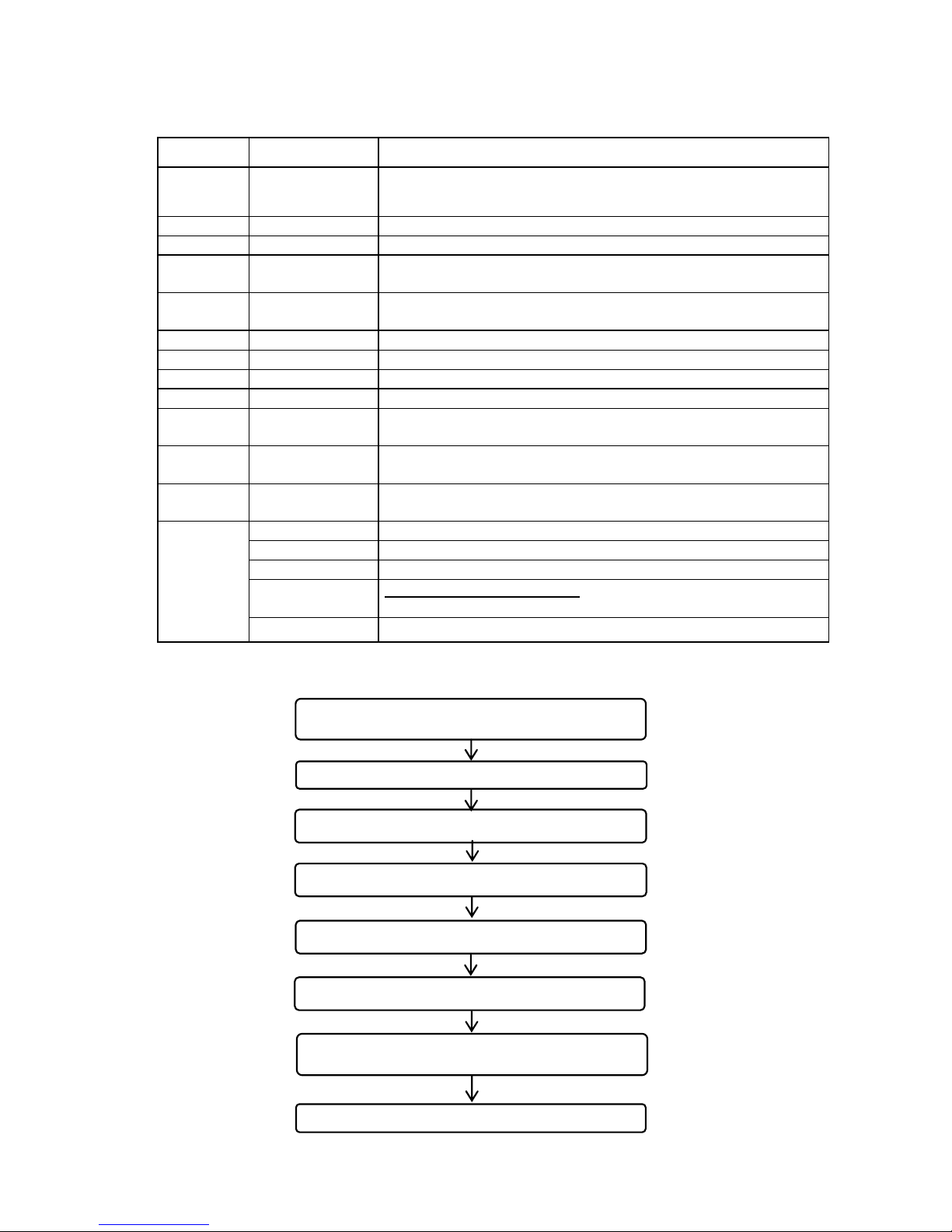
4. Remote Control RF code Setup
Install the device; pull out 20pin wire from J1
and switch off the batter
y
Press and hold SOS button
Turn on power (plug into J1). A beep will be heard
Press any key of the remote control
A beep will be heard. Then release the SOS button
Turn off power again. (pull out 20pin wire)
Power on (plug 20pin wires into J1),
the device works again
test the remote control
- 22 -
 Loading...