

SkyMate 100 SentryMate Installation Manual
SkyMate 100 SentryMate
Release 1.0
Installation Guide
SkyMate, I nc.
14000 Willard Road
Chantilly, VA 20151 USA
Part Number IGSM-10-001

2
Installation Guide
CONFIDENTIAL AND PROPRIETARY Release 1.0
Legal Notice
Copyright © 2004 SkyMate, Inc. All rights reserved.
The contents of this document constitute valuable proprietary and confidential property of SkyMate, Inc. and are provided subject to
specific obligations of confidentiality set forth in one or more binding legal agreements.
For technical information on SkyMate, Inc. products, go to:
http://www.skymate.com

Release 1.0 CONFIDENTIAL AND PROPRIETARY Installation Guide 1
Contents
1 Installation 3
Installation Overview 3
Selecting a Location for the Communicator 3
Selecting a Location for the VHF Antenna 4
Unpacking Your SkyMate SentryMate Communicator 5
Installing the SkyMate SentryMate Communicator 6
Installing the Optional Reserve Battery 7
Installing the VHF Antenna 7
Connecting the Serial Cable and the GPS Cable 7
Connecting the VHF Antenna Cable and the Main Harness Assembly 8
Connecting the Main Harness Assembly 8
Connecting the Power Cable 9
Connecting the VHF Antenna Cable 9
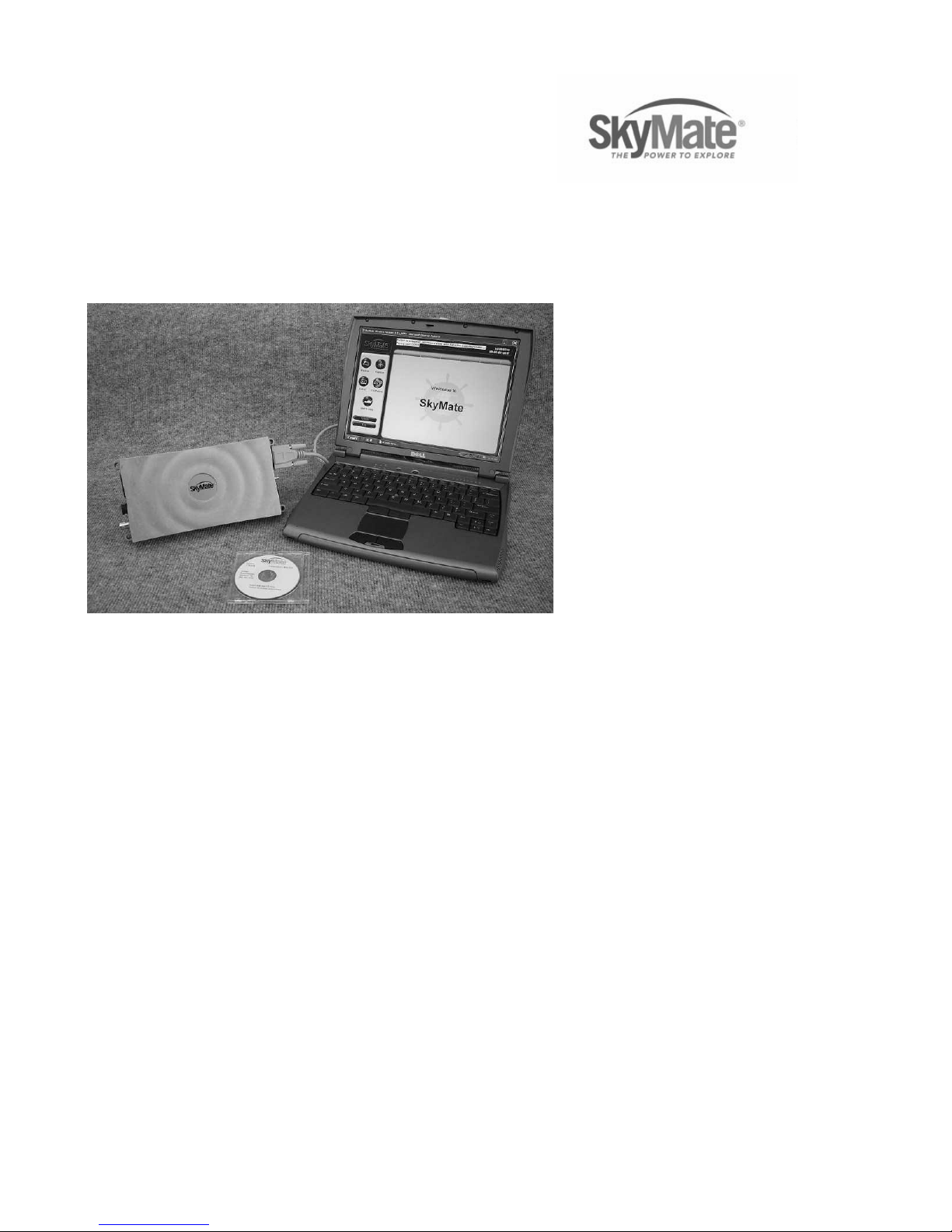
Connecting the Communicator to the PC 9
Installing the Mode Control Switch 9
Installing the Shore Power and the Auxiliary Shore Power Sensors 10
Connecting the Shore Power and the Auxiliary Shore Power Sensors 10
Connecting the Mode Control Switch 10
Connecting the Bilge Level Sensor 10
Connecting DC Power 11
Verifying that Communicator is Operating 12
Installing the Software 12
Activating Your SkyMate Communicator Account 13
Checking Satellite Availability 15
Coverage 15
2 Service and Maintenance 17
Adjustments or Repair 17
Maintenance 17
Requirements and Notices 17
FCC Compliance Statement 18
Safety Notice 18
Warranty 18
Contacting SkyMate 18
Technical Support 18
Internet Support 19

Contents
2 Installation Guide CONFIDENTIAL AND PROPRIETARY Release 1.0
Accessories and Parts 19
Specifications 19
A Appendix 21

1
Release 1.0 CONFIDENTIAL AND PROPRIETARY Installation Guide 3
1Installation
This Guide explains the basics for installing the hardware and software for your
SkyMate 100 SentryMate.
Installation Overview
Thank you for choosing the SkyMate 100 SentryMate. This document provides
step by step instructions on installing and activating the SkyMate 100 SentryMate
system for your vessel. The steps required to complete the installation and
activation are:
• Install the SkyMate 100 SentryMate hardware on your vessel
• Install the SkyMate 100 SentryMate software on the PC that will be connected
to your SkyMate 100 SentryMate Communicator
• Use a computer connected to the Internet to activate your account on
www.skymate.com.
NOTE Activating your SkyMate SentryMate account requires an internet
connection and can be performed either before or after you install the SkyMate
100 SentryMate system on your vessel.
Selecting a Location for the Communicator
Before unpacking your Communicator, you should choose a location for installing
the Communicator, its optional reserve battery, and the VHF antenna.
When selecting a location, consider the following:
❍ Select a location that is dry, well ventilated, and protected from the
elements and from high temperatures and excessive vibration.
❍ Make sure there is enough space on either side of the Communicator for
the cables.
❍ Locate the Communicator near a power source.
❍ Make sure the Communicator is not near electronic devices such as motors
and generators that may cause interference.
❍ Make sure the Communicator is within ten feet of the PC.

Installation
Selecting a Location for the VHF Antenna
1
4 Installation Guide CONFIDENTIAL AND PROPRIETARY Release 1.0
❍ Select a location to install the reserve battery. Typically, the reserve battery
is installed on the top surface of the Communicator, within easy reach of
the one foot cable that connects the reserve battery to the Communicator.
If you choose a different location, ensure that the reserve battery cable is
within reach.
❍ Select a location that provides a panel for mounting the message indicator
light, which must be installed within four feet of the Communicator.
Selecting a Location for the VHF Antenna
1 Choose a location with a clear view of the sky, free of any obstructions.
2 Position the SkyMate SentryMate VHF antenna at least four feet (preferably six
feet) from any other VHF band antenna and at least three feet from any metal
structure. Antennas closer than four feet, whether active or not, can cause
distortion of the antenna pattern and cause poor performance. The following
antennas are considered VHF antennas: VHF radio, Loran, differential GPS,
AIS, and 2-meter band.
3 You must ensure that any other installed antennas are placed an appropriate
distance from your SkyMate SentryMate VHF antenna. We recommend the
following:
You must consider the following when installing the VHF antenna:
❍ The same guidelines that apply to standard marine VHF antennas apply to
your SkyMate SentryMate VHF antenna.
❍ The coaxial VHF antenna connects to the SkyMate SentryMate antenna
with a BNC VHF connector.
❍ If a longer cable length is required, use an RG-58 (50 OHM) coaxial cable
or the equivalent, up to a maximum length of 50 feet.
VHF radio antenna 6-8 feet
Loran antenna 6-8 feet
Differential GPS antenna
6-8 feet
AIS antenna 6-8 feet
2-meter band antenna 6-8
feet
Structure (tower, mast) 4
feet
GPS antenna (L-band) 1
foot
Cellular antenna 3 feet
SSB or HF antenna 4 feet
GEO satellite radome 4
feet

Release 1.0 CONFIDENTIAL AND PROPRIETARY Installation Guide 5
Installation
Unpacking Your SkyMate SentryMate Communicator
1
❍ If a cable length greater than 50 feet is required, we recommend you use a
low loss RG-8x or equivalent cable to avoid signal loss.
❍ If the RF connector or the antenna is exposed to the marine environment,
apply a protective coating of grease such as Dow Corning DC-4 or the
equivalent.
❍ Other extensions or adaptors in the cable run must also be protected by
silicon grease and wrapped in waterproof tape.
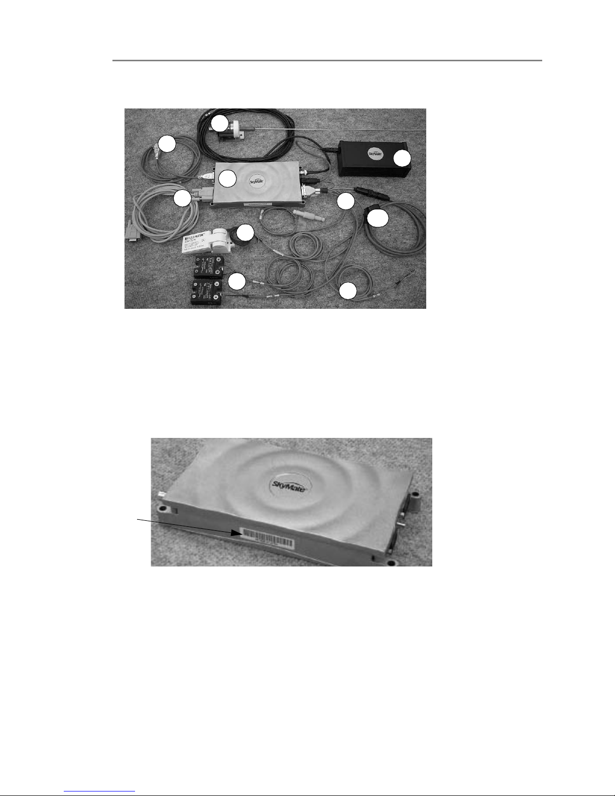
Unpacking Your SkyMate SentryMate Communicator
When you unpack your SkyMate SentryMate Communicator, make sure you have
all the parts listed below. See Figure 1-1 on page 6 for an overview of the
Communicator parts. If any parts are missing, contact SkyMate SentryMate before
proceeding with installation. We recommend that you keep the shipping material in
case you need to return your SkyMate SentryMate Communicator for any reason.
1. SkyMate SentryMate Communicator
2. Main harness assembly, which includes the following:
❍ 12 Volt power cable
❍ 4-pin twist lock connector for the power cable
❍ 2-pin twist lock connector for the reserve battery cable
❍ 3-pin twist lock connector for the message indicator light
❍ Shore power and auxiliary shore power sensors cable
❍ Bilge level sensor cable
3. Mode control switch
4. Optional reserve battery
5. VHF antenna with cable assembly
6. Serial cable for connection to PC
7. Bilge sensor
8. Shore power and auxiliary shore power sensors
9. Cable provided for optional security sensor (security sensor is not
supplied)
10. GPS or GPS Y cable
11. Software CD (not shown)
12. User documentation (not shown)
Installation
Installing the SkyMate SentryMate Communicator
1
6 Installation Guide CONFIDENTIAL AND PROPRIETARY Release 1.0
Figure 1-1. Overview of Communicator Parts
IMPORTANT
Make a note of the Dealer code and the SCID code for your
SkyMate 100 SentryMate. You must have this information available when you
install your SkyMate SentryMate software and activate the unit. See Figure 1-2
for the location of the SCID code. You will find the Dealer code listed in your
Quick Start guide and a space to write the SCID code.
Figure 1-2. SCID Code Location
Installing the SkyMate SentryMate Communicator
Typically the Communicator is mounted on a shelf, in a cabinet, or on a bulkhead.
1 Place the Communicator on the mounting surface.
IMPORTANT If you are installing the reserve battery on the top surface of the
Communicator (as recommended) perform this step now, before attaching the
Communicator to the mounting surface. This allows you to secure the reserve
battery to the Communicator with the supplied dual lock fasteners.
1
2
3
4
5
6
7
8
9
10
SCID
Code
Location
Release 1.0 CONFIDENTIAL AND PROPRIETARY Installation Guide 7
Installation
Connecting the Serial Cable and the GPS Cable
1
2 Attach the flange to the mounting surface.
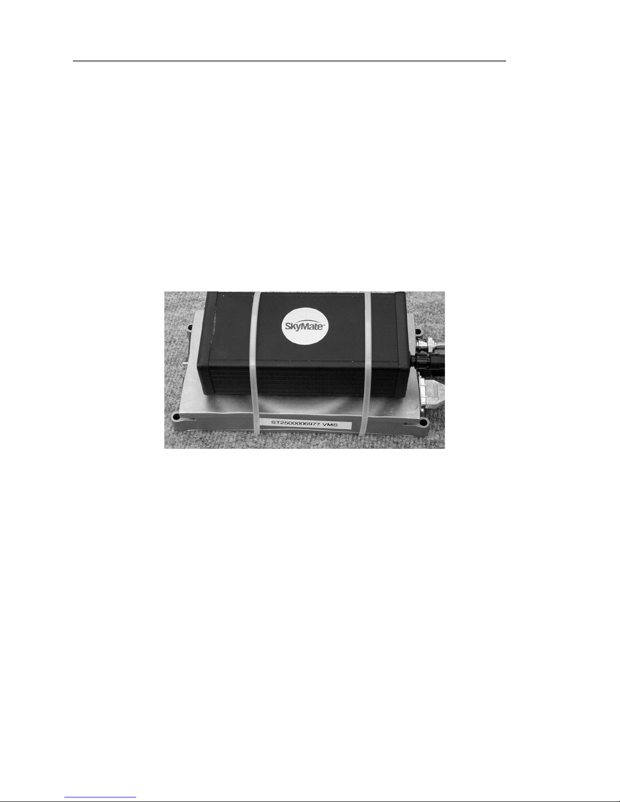
Installing the Optional Reserve Battery
Typically the reserve battery is attached to the Communicator using the supplied
Dual Lock Reclosable 3M fasteners and cable ties. See Figure 1-3. To install the
reserve battery:
1 Place the reserve battery on the top surface of the Communicator.
IMPORTANT Make sure that the reserve battery is oriented to face the power
connector on the Communicator labeled “PWR”.
2 Attach the reserve battery to the Communicator’s top surface using the dual
lock fasteners.
3 Place the cable ties around the reserve battery and secure the cable ties.
Figure 1-3. View of Installing the Optional Reserve Battery
Installing the VHF Antenna
1 Connect the coaxial cable to the base of the VHF antenna using the black tool
provided. (The other end of the cable plugs into the Communicator.)
2 Mount the VHF antenna on a standard 1 1/4 inch threaded mount.
There must be a clear view of the sky. You must ensure that no other VHF
antenna (active or inactive) is within four feet (preferably six feet) of the
SkyMate SentryMate VHF antenna.
Connecting the Serial Cable and the GPS Cable
1 Attach the serial cable (1) to the serial cable connector on the Communicator
marked “Serial”.
2 For an external GPS connection, connect the high density 15-pin end of the
GPS cable (2) to the connector marked “AUX”. Connect the standard 9-pin
end to the external GPS device (not supplied).
 Loading...