

SKYLUX Skycom Skymax CE 24V/5A, Skycom CE MASTER, Skycom CE SLAVE User Manual And Installation Instructions
Page 1
Release: 10-2016
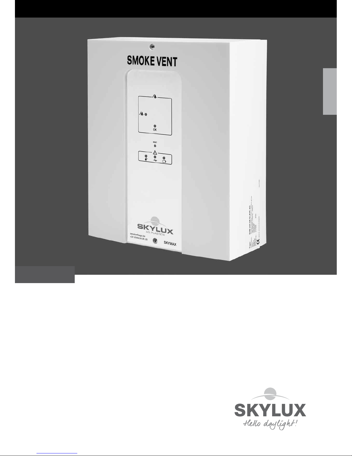
SMOKE AND HEAT EXTRACTION CONTROL
EN
Skycom Skymax CE
24V/5A
User manual and installation instructions
ENGLISH
Page 2

E_MH_Installation_instruction_Skycom_Skymax_CE 01/10/2016
2/26
YOUR SHE-SYSTEM DESCRIPTION
Address of installation
Name: ...............................................................................................................................................................................
Address: ........................................................................................................................................................................
Phone no.: ........................................................................................................................................................................
Contact person: .................................................................................................................................................................
Date of installation: ............................................................................................................................................................
System Description
Number of SHE control: Number of opening system(s):
Master(s) (24V/8A): .................................. Skylux 160° CE: ..................................
Slave(s) (24V/8A): .................................. Skymax CE: ..................................
Skymax (24V/5A): .................................. Skymax Standard: ..................................
Cintramax CE: ..................................
Skyvent CE: ..................................
other systems: ..................................
External controls (AFA: Automatic Fire Alarm - CCS: Climate Control System): ..................
230V power supply from circuit N°: ..................
Your SHE-System description............................................................................................................................. p. 2
Table of contents.................................................................................................................................................. p. 2
Introduction........................................................................................................................................................... p. 3
SHE survey AG.Plastics ...................................................................................................................................... p. 4
Safety & warnings................................................................................................................................................ p. 5
General description.............................................................................................................................................. p. 6
Installation.......................................................................................................................................................... p. 6
Connection, operation and settings................................................................................................................ p. 8
Motor (actuator)....................................................................................................................................... p. 8
Fire switches............................................................................................................................................ p. 10
External priority switch............................................................................................................................. p. 11
Smoke-/heat detectors............................................................................................................................. p. 12
Comfort ventilation + setting roof access................................................................................................ p. 12
Weather sensor / Close all functions....................................................................................................... p. 13
External signal output, re alarm panel and other systems..................................................................... p. 13
More control units linked to one re group (bus connection)................................................................... p. 14
Special functions...................................................................................................................................... p. 15
Electrical schemes............................................................................................................................................. p. 16 - 18
Main scheme (control PCB with factory settings)................................................................................... p. 16 - 17
Skymax CE (with positive safety)............................................................................................................ p. 18
Settings (jumpers, dip switch, ... ) ...................................................................................................................... p. 19
Frontpanel............................................................................................................................................................ p. 20
LED indication (external & internal)................................................................................................................... p. 21
Cables................................................................................................................................................................. p. 22
Maintenance........................................................................................................................................................ p. 23
Spare parts and accessories............................................................................................................................... p. 24
CE Declaration of conformity............................................................................................................................... p. 25
Technical specications.................................................................................................................................... p. 26
Revisions.............................................................................................................................................................. p. 26
TABLE OF CONTENTS
Page 3
01/10/2016
3/26
E_MH_Installation_instruction_Skycom_Skymax_CE
INTRODUCTION
Why do you need to foresee Smoke and Heat Extraction (SHE)?
In case of re, it is not the re itself, but the smoke gasses that make most victims. The heat and smoke gasses ll the
building, which complicates evacuation. Skylux developed different natural SHE systems which create smoke free zones
and bring down temperature during re, which enables a quick and safe evacuation.
SHE systems are legally required in specic buildings. In such buildings, only CE certied systems, in accordance with
European (and Belgian) norms, are allowed to be used.
At the same time, our SHE systems provide free natural daylight and daily ventilation.
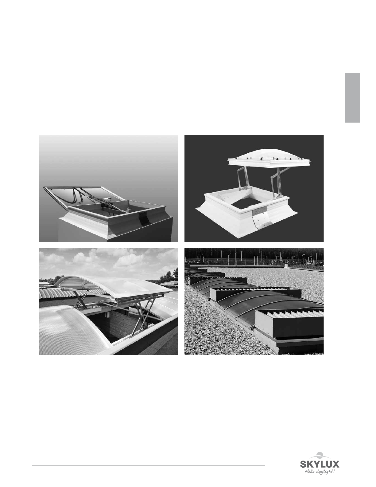
Skylux‘ SHE systems:
Each of these SHE systems can be operated by a Skycom® CE Master control, possibly in combination with a Skycom®
CE Slave control.
We developed also a control unit fort he Skymax® CE : the Skycom® Skymax® CE control.
The SHE survey (p. 4) mentions the combinations of control units and smoke hatches allowed and supported by Skylux.
Skyvent® CE
Skylux® 160° CE Skymax® CE
Cintramax® CE
ENGLISH
Page 4
E_MH_Installation_instruction_Skycom_Skymax_CE 01/10/2016
4/26
SHE TABLE
1. The SHE-control must be installed or serviced by a qualied person, authorised for working at electrical Smoke and Heat
Extraction systems. The control and accessories must be installed according to the local norms.
2. Service!
Before installation or service disconnect electrical power and remove the indicated terminal of the battery. Afterwards
reconnect the terminal, mount the housing before switching on electrical power. Now you can test the complete installation.
3. Service of opening system:
Before servicing the opening system, make sure the opening system can not start to move unexpectedly. Therefore
remove the 8 A glass-fuse before starting service at the opening system. This disables the main supply and the battery
supply of the opening system.
4. Batteries:
- To avoid explosion danger follow these safety rules:
• Never short circuit a battery.
• Do not use external chargers. Explosive gasses can be released.
• Always handle batteries with care as they contain strong acids.
- Avoid to store controls with batteries for a long time. Batteries which are not used must be recharged (unload & load)
every 3 months to slow down the capacity loss.
- Don’t discharge batteries to deep as they might be damaged.
- There is no guarantee on batteries.
5. Guarantee expires:
• If controls or cables (especially motor cable) are wrongly dimensioned;
• If non-original parts are used. Use only original parts delivered by AG.Plastics. Especially take care to use a
control which is suitable for the SHE opening system;
• If opening systems are not connected according the installation instructions. Most opening systems must be
connected through a limit switch. Please consult thoroughly the electric scheme of the appropriate SHE system
before connection.
6. Next to the installation of a SHE system, make sure you take all necessary steps to be able to proceed to a smooth
evacuation. Foresee several escape routes, make sure the remen can reach easily the re place. See to the possibility
of a quick signal to the re department in case of re by a full re detection system,… Consult your architect, constructor
and re-department.
7. The SHE-system needs mains voltage. In case of power failure, the system will continue to operate on its batteries in a
limited period of time (min 72 h).
8. Mains power failure g putting out of service:
If the mains voltage is switched off for a longer period of time (> 1 day), disconnect the indicated pin of the battery and
insulate the wire end. Otherwise, you will risk that the batteries discharge and will be damaged.
9. There is a possibility that the smoke does not reach the detector due to chimney effects through walls, shafts, roofs. Also
behind a closed door or at another oorlevel may the smoke not be detected. A detector may be less sensitive to certain
types of re so that the signal is given in a later phase. Make sure to install sufficient detectors at right places.
10. It may occur that the opening system is not correctly operated due to a panic situation in case of re.
11. The SHE-control does not protect people or objects from being stuck when the actuators are activated. This must be
done externally.
12. The manufacturer is not responsible for the loss of a life or materials caused by re, smoke, wind, rain, … even when
the rain- and wind detector is connected. Make sure no damage (wind, rain, …) can be caused during uncontrolled open-
ing of the system.
13. The SHE-control and accessories must not be used as connector box for cables ! Use an external connector box.
14. The wiring for the accessories (re push buttons, detectors, prior key contact, ...) must be at least 1 m off other current
wires (not in the same wire drain) to prevent from interference.
15. We reserve the right to modify this manual or the products without prior notice. You can always check the newest ver-
sion on www.agplastics.com.
16. The responsible person must keep this manual, if possible near the control unit.
17. In particular cases due to fall-through safety, it’s forbidden to open the smoke hatches more than 30 cm for ventilation.
SKYCOM
SKYMAX®*
Art.nr. 34072
PRIOR SWITCH
Art.nr. 32569
with Skymax CE
with positive safety (opens automatically)
SKYCOM
MASTER
Art.nr. 30975
with Skymax CE
without positive safety
(does NOT open automatically)
Cable sections in function of the distance
SKYCOM
MASTER
Art.nr. 30975
SKYCOM
SLAVE*
Art.nr. 30977
with Skylux 160° CE
SKYCOM
SLAVE*
Art.nr. 30977
with Cintramax CE
SKYCOM
MASTER
Art.nr. 30975
* Important: with positive safety: always install a Skycom control unit (Slave or Skymax) at the
ceiling, as near as possible to the opening system (max 5m).
Other combinations are usually NOT COMPLIANT!
Page 5

01/10/2016
5/26
E_MH_Installation_instruction_Skycom_Skymax_CE
SAFETY & WARNINGS
1. The SHE-control must be installed or serviced by a qualied person, authorised for working at electrical Smoke and Heat
Extraction systems. The control and accessories must be installed according to the local norms.
2. Service!
Before installation or service disconnect electrical power and remove the indicated terminal of the battery. Afterwards
reconnect the terminal, mount the housing before switching on electrical power. Now you can test the complete installation.
3. Service of opening system:
Before servicing the opening system, make sure the opening system can not start to move unexpectedly. Therefore
remove the 8 A glass-fuse before starting service at the opening system. This disables the main supply and the battery
supply of the opening system.
4. Batteries:
- To avoid explosion danger follow these safety rules:
• Never short circuit a battery.
• Do not use external chargers. Explosive gasses can be released.
• Always handle batteries with care as they contain strong acids.
- Avoid to store controls with batteries for a long time. Batteries which are not used must be recharged (unload & load)
every 3 months to slow down the capacity loss.
- Don’t discharge batteries to deep as they might be damaged.
- There is no guarantee on batteries.
5. Guarantee expires:
• If controls or cables (especially motor cable) are wrongly dimensioned;
• If non-original parts are used. Use only original parts delivered by AG.Plastics. Especially take care to use a
control which is suitable for the SHE opening system;
• If opening systems are not connected according the installation instructions. Most opening systems must be
connected through a limit switch. Please consult thoroughly the electric scheme of the appropriate SHE system
before connection.
6. Next to the installation of a SHE system, make sure you take all necessary steps to be able to proceed to a smooth
evacuation. Foresee several escape routes, make sure the remen can reach easily the re place. See to the possibility
of a quick signal to the re department in case of re by a full re detection system,… Consult your architect, constructor
and re-department.
7. The SHE-system needs mains voltage. In case of power failure, the system will continue to operate on its batteries in a
limited period of time (min 72 h).
8. Mains power failure g putting out of service:
If the mains voltage is switched off for a longer period of time (> 1 day), disconnect the indicated pin of the battery and
insulate the wire end. Otherwise, you will risk that the batteries discharge and will be damaged.
9. There is a possibility that the smoke does not reach the detector due to chimney effects through walls, shafts, roofs. Also
behind a closed door or at another oorlevel may the smoke not be detected. A detector may be less sensitive to certain
types of re so that the signal is given in a later phase. Make sure to install sufficient detectors at right places.
10. It may occur that the opening system is not correctly operated due to a panic situation in case of re.
11. The SHE-control does not protect people or objects from being stuck when the actuators are activated. This must be
done externally.
12. The manufacturer is not responsible for the loss of a life or materials caused by re, smoke, wind, rain, … even when
the rain- and wind detector is connected. Make sure no damage (wind, rain, …) can be caused during uncontrolled opening of the system.
13. The SHE-control and accessories must not be used as connector box for cables ! Use an external connector box.
14. The wiring for the accessories (re push buttons, detectors, prior key contact, ...) must be at least 1 m off other current
wires (not in the same wire drain) to prevent from interference.
15. We reserve the right to modify this manual or the products without prior notice. You can always check the newest version on www.agplastics.com.
16. The responsible person must keep this manual, if possible near the control unit.
17. In particular cases due to fall-through safety, it’s forbidden to open the smoke hatches more than 30 cm for ventilation.
ENGLISH
Page 6

E_MH_Installation_instruction_Skycom_Skymax_CE 01/10/2016
6/26
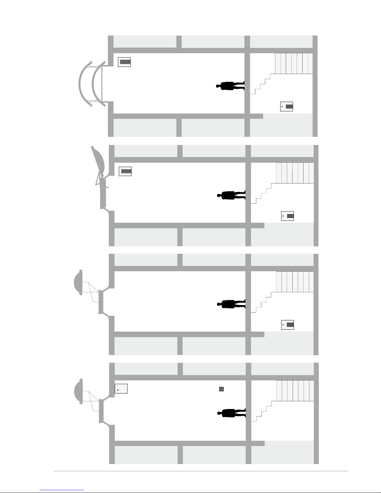
The Skycom CE controls are intended for opening of skylights, smoke hatches, ... for Smoke and Heat Extraction (SHE)
and comfort ventilation of 1 re zone.
The Skycom Skymax CE control is typically used to command 1 Skymax smoke hatch in a staircase.
The Skycom Skymax control has the following operation possibilities (upon accessories):
Operation for Smoke and Heat Extraction (control in Alarm-status):
1. Automatically activated: by smoke or heat detectors. Each control has also an internal T-sensor which generates
alarm at 75°C.
2. Activated by passer-by: on ‘break-glass’ re-switches
3. Operation by remen: possibility for priority open and close on the priority switch for remen
Operation for comfort ventilation:
Activated by opening-closing switches (push buttons) or by weekly timer, room thermostat,
outdoor weather sensor.
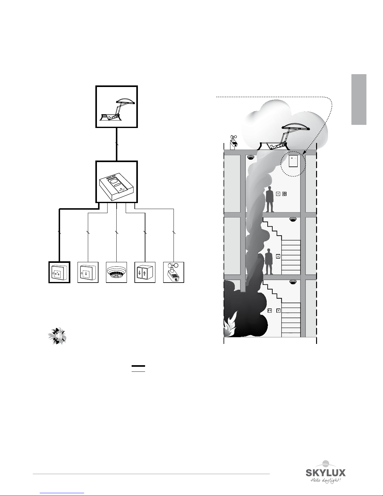
The operation status (OK / alarm / fault / smoke hatch open) is indicated by Led’s and is also available on outputs for connection with other systems (AFA-systems, Air-gates, buzzer, ...) in the building.
We advise to consult your re department to choose the best installation place fort all SHE accessories. You’ll nd an
example on page 7. Generally, install the control panel for the remen (prior switch) at a visible place and easy to be
reached, on the access road of the remen with the bottom at 1,35 - 1,45 m above the oor in the entrance hall of the
(main) building.
The Skycom Skymax CE Slave control must be installed as close as possible (max. 5 m) to the opening system, i.e. at
the ceiling of the building or against the roof opening.
The control unit weights 7,5 kg and must be installed on a stable underground. The mounting holes for wall mounting
are placed on the metal plate underneath the plastic lid.
Foresee (at least) a separate 230V power circuit with its own automatic circuit breaker for each re zone. Don’t connect
other devices to this circuit!
It is sometimes required to supply the control unit with a 230V circuit with separate earth leakage circuit breaker and that
a circuit breaker is installed on the actuator line.
GENERAL DESCRIPTION
INSTALLATION
Page 7
01/10/2016
7/26
E_MH_Installation_instruction_Skycom_Skymax_CE
n
SCHEME
SKYMAX® CE
SKYCOM
SKYMAX CE
FIRE SWITCH
RAIN – AND WIND DETECTOR
COMFORT VENTILATION
SMOKE AND HEAT SENSOR
*1
*2
*3 *4 *6*5 *
7
4 x 0,5 mm
2
fireproof
6 x 0,5 mm22 x 0,5 mm23 x 0,5 mm23 x 0,5 mm
2
standard
standard
fireproof
fireproof
Max. 5m
fireproof
2 x 1,5 mm
2
PRIORITY SWITCH
only for firemen
option
standard
*1
*2
*3
*4
*4
*4*6
*5
*5
*5
*7
at the ceiling, as near as possible to the smoke hatch
ENGLISH
Page 8
E_MH_Installation_instruction_Skycom_Skymax_CE 01/10/2016
8/26
Connection, operation and settings
Motor (actuator)
The actuators must be connected to output terminals 2-3. The max. load is 5A.
It is possible to disable the line monitoring on the motor output. The cables can be connected in series or parallel or a
combination of these (see drawings motor and electrical schemes).
It is important to keep the right polarity. The motors of most systems must be connected via a limit switch - see electrical
scheme of the specic opening system.
See table at the end for cable sections and max. motor cable length.
Cable monitoring (line monitoring) on the motor output
The control is equipped with 3 possible settings for cable monitoring (line monitoring), which can be congured by
means of jumper J2.
a. Jumper J2 mounted in pos. “Motor line” (Setting for Skylux® 160° CE, Skymax® CE old and new and Cintramax® CE)
Known motor: line monitoring (2-3) with double wired motor connexion.
Jumper J3 (actuator output) is set according to the number of termination resistors (27KΩ) to be detected – 1 to max. 4
lines can be detected by moving jumper J3 – this means that the cable installation between the control unit and the motors
can be established in series connection (cable connection from smoke hatch 1, further to smoke hatch 2, etc.), or parallel
connection (cable connection from each smoke hatch to the control), or a combination of these. However, as mentioned
max. 4 different lines can be detected, each of them connected to the end resistor of 27KΩ.
Jumper description
J3
Number of connected 27Kohm terminal
resistors for actuator output
J2
Chooses line monitoring through motor
terminals 2-3 (Mot Mon) or separate
wire terminals 1-3 (Ext Li Mon), or no
line monitoring when J2/J3 is removed
F1
Fuse 8A for actuator output
Line 1
1
CH 1
24V Out
Actuator
23
+-
5
LIP
2
1
4
6
3
M1
24V Out
Actuator
2
1
Actuator
Motor line monitor
Ext 3 wire monitor
(line 1)
Blue
Next LIP
Brown
Blue
J2
1
J3
4
3
2
1
M2
Blue
Brown
Page 9

01/10/2016
9/26
E_MH_Installation_instruction_Skycom_Skymax_CE
b. Jumper J2 in pos. “Ext 3 wire” (Setting for Skymax® standard / Cintramax® CE (old) / Skyvent® CE)
Unknown motor: line monitoring (1-3) with 3 wired motor connexion.
With jumper J3 (actuator output): you choose how many lines (number of 27KΩ)
you wish to detect - the same way as the motor line.
This setting demands 3 wire cable from motor output to motor.
c. Jumper J2/J3 is not mounted - No line monitoring for actuator output
Electronic current limiter, type LIP function and setting (Skylux 160°CE, Cintramax CE, Skymax CE)
The current limiter type LIP (mounted on the opening system) is used as current limiter for the actuator. On the LIP5, and
younger version max. 3 times overload cut outs in the same direction is allowed. After which it will not be possible to run
in this direction again, before the motor has run in the opposite direction. Please note that when opening, the red LED in
the LIP must light. This indicates that polarity of the actuator is correct.
Table of LIP settings
* SA Power LM Large - parallel operation: Jumper OPT mounted - both motors stop at the same time if one stops
because of overload.
** When DIP4 is OFF = Tandem Mode - both motors stop at the same time if no current ows in one (1,5 sec. reaction
time).
*** Required: an actuator with “read” sensor (3-wire sensor black cable included).
Actuator
24V Out
1
+
21
Line 1
-
3
2
3
4
J2
J3
Mn M2 M1
Actuator
Motor line monitor
Ext 3 wire monitor
(line 1)
27K Ohm
(Only last
actuator)
Opening system
Skylux 160° LM Skylux 160° LM Skylux 160°: Mini + RM
Cintramax Skymax
current limit
3A 4A 2,5A
DIP 1 ON OFF ON
DIP 2 OFF ON ON
Type DIP 1 DIP 2 DIP 3 DIP 4 DIP 5 DIP 6 DIP 7 DIP 8
LIP5
Single
See diagram
above
27K
ON
not present
LIP6 *
Double
ON OFF ** =
Tandem
27K ON M1-M2 delay=OFF not present
LIP7
Single
Basic
27K
ON
not present
LIP7
Single
Tandem
27KONON =
COM
OFF = Slave
ON = Master
OFF = Synchro Mode
ON = Tandem Mode
off: no delay
on: 7s delay
no function
1
2
13
2
3
4
J2
J3
M1
Actuator
Motor line monitor
Ext 3 wire monitor
(line 1)
ENGLISH
Page 10

E_MH_Installation_instruction_Skycom_Skymax_CE 01/10/2016
10/26
Fire switches
The re switch will contain the following:
• Breakable glass window and red control button, activated by pressure - this puts
the control unit in ALARM status, by which the motor output is activated (for
normal service and testing the lid can be opened with a key).
• RESET button which brings the control unit out of the alarm status and starts
the closing sequence for about 180 seconds. Please note that RESET does
not cancel errors in the system, e.g. line errors etc. These must be found and
corrected. When a detector is still alive after reset, the control will go immediately
in alarm status again.
• RED LED indicates that the control unit is in ALARM status and that the motor
output either is or has been activated.
• YELLOW LED indicates faults on the system - please call for a service
technician.
• GREEN LED indicates that the system is in normal operation status without
errors.
The master control has an integrated priority re switch.
Additional connection of the external re switches are made as shown on the
drawing.
When the control is fully loaded, max. 8 external re switches can be connected.
When there is no load (Master), max. 10 re switches can be connected.
The installation with re switches must be terminated with a resistor (10kΩ 27kΩ) in the last switch in order to establish the line monitoring correctly – this
can either be done by moving the factory mounted resistor from the terminal
strip to the last re switch or connect jumper J1 in the re switch (by this a
10KΩ resistor is also connected).
By means of DIP switches the control unit has different possibilities of settings
for the input to the re switch:
DIP 1 (Con.Fire.Sw):
On = ALARM status from 500-3KΩ, (indication of line error by direct short circuit
or open circuit).
Off = ALARM status from 0-3KΩ (indication of line error by open circuit).
DIP 2 (Fail Safe):
On = Any line error on re switch or smoke detector puts the control unit in
ALARM status. This function can be used if cables to re switches and smoke
detectors are not reproof.
Off = An error status does not report ALARM status.
Terminals BVT
1. green LED OK (lights when OK and while closing)
2. yellow LED (lights on error)
3. red LED alarm (emergency opening)
4. ground (-)
5. not used
6. re switch reset
7. re switch emergency opening
Jumper J1 must only be set in
the last or only re switch
Fail. 24V
ALARM
OK 24V
6
4
3
2
1
4
3
2
1
J1
7
6
4
3
2
1
Gnd
11 12
24V
10 13
7
J1
7
6
FIRE15Reset
14
21
FAIL SAFE
Con. Fire. Sw
DIP
NO
OFF
ON
Red LED
Yellow LED
Green LED
2,2 kΩ
2,2 kΩ
10
K
Ω
Last manual control
point
Fit Jumper J1 for line
monitoring
Manual control point.
Break glass (BVT) No. 1
10
K
Ω
Break glass (BVT)
1
Buzzer
3
4
6
7
LED
OK
LED
2
i
LED
Alarm
GND
Reset
24V
24V
Green
Yellow
Red
24V
2,2k
Ω
J1
Jumper
10k
Ω
Reset
Alarm
doorswitch
FIRESWITCH
SKYCOM CE
10 1512
11 14
13
Page 11

01/10/2016
11/26
E_MH_Installation_instruction_Skycom_Skymax_CE
External priority switch for remen
The optional add-on PCP (SVM AddOn) is already connected. With correct SW (Version 042 or higher), LD3 + LD2 ash
for 5 sec. when communication has started. Connect the priority switch as shown on the electrical scheme. Line monitoring is done on the close (1-3) and open (1-4) outputs of the “add-on” PCB and is indicated by LD3 and LD2. Therefore
in the priority switch 10kΩ resistors are integrated. To avoid confusion there can be only one priority switch.
Information about the LED-indications: see page 21.
SVM addon
54321 6
CLOSE OPEN
16
GND
OPEN
CLOSE
LED
AL
MAIN PCB
If present, remove resistors
when connecting priority switch
LED
CLOSE
OPEN
GND
GND
GND
POWER
OPEN
CLOSE
PRIOR
external priority switch
CONTROL
LINK
PROGRAM
LD1
LD2
LD3
GRE
RED
RED
ComfortWeather
24V
Gnd
Weather
22 23
Gnd
20 21
PRIOR
ENGLISH
Page 12

E_MH_Installation_instruction_Skycom_Skymax_CE 01/10/2016
12/26
Nr.2-20
L2
L2
Nr.1
16
Gnd17Smoke
10
K
Ω
L1 Out
Smoke or heat sensors
L1 In
L1 Out
L1 In
(only last sensor)
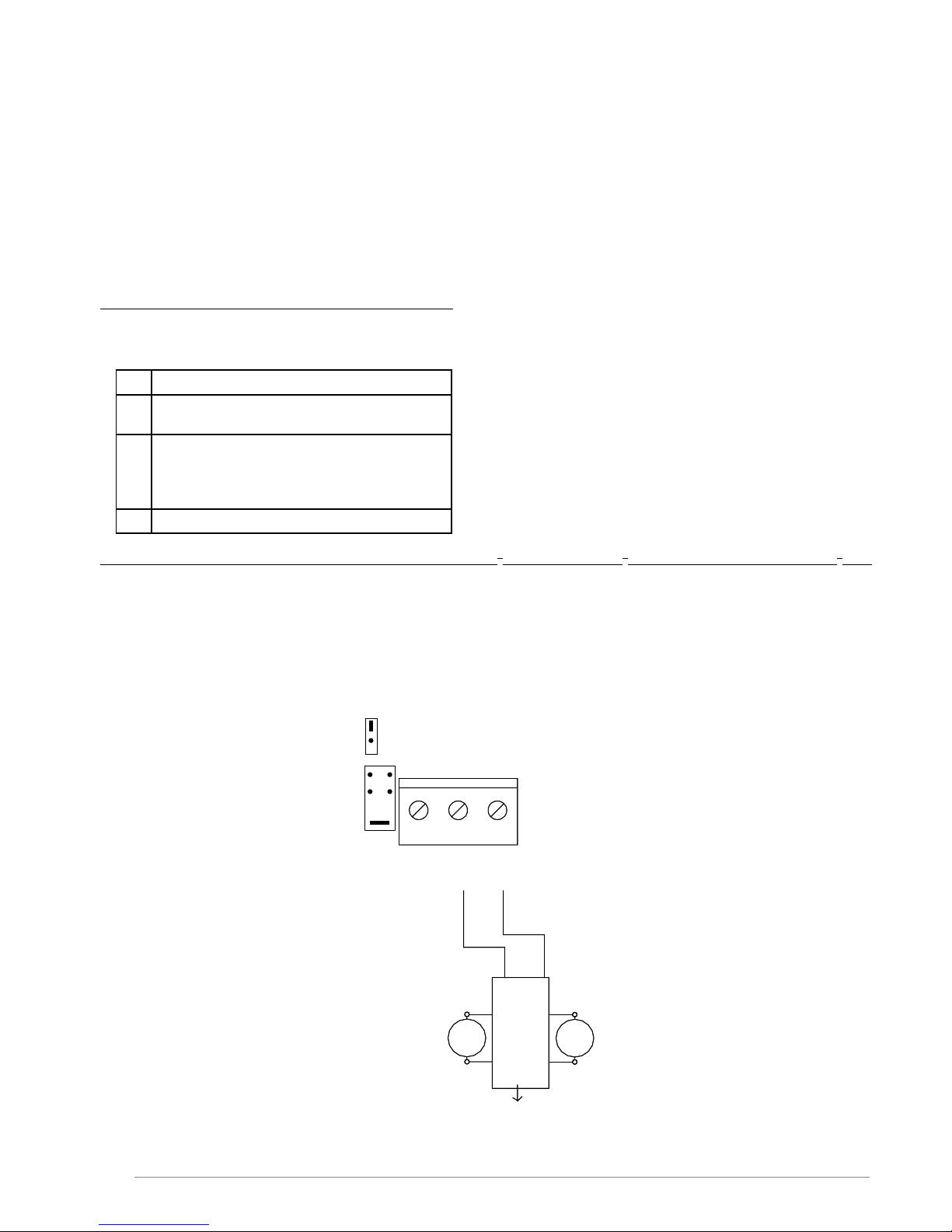
Smoke- / heat detectors
Smoke- and heat detectors are connected as shown.
Line monitoring: Correct line monitoring can only be guaranteed with detectors delivered
from the supplier. Other detectors may have different internal resistances and stand by
power consumption.
Connect max 20 pc per control.
Comfort ventilation
The motor output can be controlled separately with comfort switch(es).
The master control has already integrated comfort open/close buttons.
Additionally external comfort switches can be connected as shown on the scheme.
It’s possible that due to fall-through safety, it’s forbidden to open the smoke hatches more than
30 cm for ventilation.
For comfort ventilation there are the following possibilities:
Potentiometer in Puls position:
It is possible to press the »up« button 3 times, which each gives 10 seconds of opening time after that nothing happens – Continuous »up« signal gives 3x10 sec.= 30 sec. - One press on
»down« closes the actuator completely; it takes 18s longer compared to fully closing time - In
order to avoid »actuator pumping« max. 3 successive closing attempts will be allowed.
Potentiometer in Constant position:
As long as »up« signal or »down« signal are given, the actuators are running. This is the
recommended position in case of e.g. roof access
Potentiometer in Puls variable position:
The time on the above mentioned pulse opening can be adjusted from 1-60 sec. on the
potentiometer.
When moving the potentiometer into the different positions the LED batt low will ash for about
4 sec. to indicate when in puls mode. LED line fail ashes 4 sec. when in Constant and AC fail
ashes when in puls Variable.
Put the potentiometer of all connected detection units (also Master) in the same position.
20
Gnd
18Up19
Down
Puls
variable
Min
Const.
Max.
Puls
YELYEL YEL
AC FAIL LINE FAIL BATT LOW
Up
Down
Switch Ch
1
Comfort
Potmeter for
comfort features
Room thermostats, weekly timers, CCS and other external control equipment for comfort ventilation can be connected to
the input of the comfort control.
Page 13

01/10/2016
13/26
E_MH_Installation_instruction_Skycom_Skymax_CE
6
NO
4
COM5NC
89
NO
NC
7
COM
Alarm Out Failure Out
Po
tential free F
ailure
contac
t.
C
om + NC connec
ted by
failure.Max 48V 0,5A
Po
tential free ALARM
contac
t.
C
om + NO connec
ted by
alarm.
Max 48V 0,5A
External signal output, Fire Alarm Panel and other control systems
The control panel can forward alarm situation to external connected systems by
means of potential free contacts on the terminals 4 (com), 5 (NC) and 6(NO).
The control panel can forward failure condition to external connected systems by
means of potential free contacts on the terminal 7 (com), 8(NO) and 9(NC).
Alarm and error contacts work parallel on all controls connected with bus connection.
DIP6 (fail relay):
On = Fail relay changes function to indicate open/closed smoke hatches.
How to make a connection from a Fire Alarm Panel
The control panel can receive potential free alarm signals from e.g.
AFA systems on the input to re switch or smoke-/heat detector.
Terminal 16 and 17.
Line monitoring resistor must be tted over the contact of the AFA system.
GND
16 17
Smoke
10 kΩ
Normally open
10 kΩ
Supplied with Panel
Weather sensor / Close all function
Install the rain- and wind detection as close as possible to the smoke hatch, at a place, where
the wind speed is equal to the wind speed of the smoke hatch (do not install the detector at eg
the outside of the roof edge trim).
The smoke hatches should be closed when the wind is above 6 m/s.
LED LD3 on the main board indicates active weather sensor - lights as long as input is active.
As long as the weather sensor is active, the smoke hatches cannot be opened with comfort
switches.
The weather sensor closes on all controls which are connected through bus connection.
On the input to weather station a weekly timer can be connected which makes sure that
everything is closed, e.g. by end of a working day.
The 24V power supply (terminal 22 & 23) for the weather sensor is standard set this
way (J11) that it does not function on batteries.
If battery functioning is needed, then mount J11.
This is possible at PCB V5 and the following versions (as from March 2015).
Be aware of the reduced standby time due to current consumptions.
Factory setting weather sensor = test = Pos 0 = delay 10s + highest sensibility.
Recommended settings weather sensor: Pos 4 = 4m/s (delay = 10 min)
For more details, consult the installation instructions of the wind-and
rain detector AWR-24/250.
Weather
24V
Gnd
Weather
22 2321
NC
NO
COM
24V
AC/DC
WIND & RAIN
AWR-24/250
ENGLISH
Page 14

E_MH_Installation_instruction_Skycom_Skymax_CE 01/10/2016
14/26
More controls connected in one re group (bus connection)
When there is only 1 control unit in the re group, terminals
A 1 2 3 and B 1 2 3 are not used. The communication is
interrupted by removing all the jumpers.
By means of a bus communication it is possible to make 2 – 35 control units to work as a complete system. The control
units communicate with each other via a 3 wire bus connection.
Terminal no. A1, A2, A3 are for the incoming connection and B1, B2, B3 for the outgoing connection.
In the rst control unit start Bus J4 has to be on. This control is Master and J5 must therefore also be on. Following control unit is a slave and therefore J6 must be connected. In the last slave unit, J7 and J6 must be connected to terminate
the bus cable.
ALARM: Alarms from Manuel Control Point smoke-/heat detectors are controlled locally. When DIP11 is set, the control
will go into alarm state if another control connected on the BUS enters alarm state.
RESET: If the reset button on one control or in one re switch is activated, the reset function on all connected controls is
activated and starts the closing function on all motor output for approx. 180 sec.
COMFORT: The comfort operation can work locally on each control. When DIP10 is set the control will react on any
comfort signal send on the bus from another control.
If a wind- and rain sensor is connected, it will work on all control on the bus matter dip settings.
Function description for control units connected with bus connection
If more control units are connected by means of a bus connection, the following are monitored/communicated between
the control units:
- A detected bus error makes the LED LD7 on the main board light/ash.
- A detected bus error brings all controls on the bus connection in error condition (line error).
- If one of the control units in the network goes into alarm status, all go into alarm status.
- If one of the control units goes into a certain error status (line error, AC error, battery error or bus error), the
other control units also go into error status – the type of the error is indicated on the board of the front plate of
all control units – on the control unit(s) which have not caused the error, the ok LED on the board of the front plate
ashes at the same time as the error. On the control unit(s) which have caused the error, the OK LED is switched
off.
Factory settings of Master, Slave & Skycom Skymax CE
J4 J5 J6 J7
Master ON ON OFF OFF
Slave OFF OFF ON ON
Skycom Skymax OFF OFF OFF OFF
START TERM.
START termination
J4
END termination
BUS Slave
BUS Master
MASTER SLAV E
J6J5
END TERM.
J7
Serial OutSerial In
A2
A1
B2
B1
A3 B3
BUS Master
START termination
BUS Slave
END termination
START termination
BUS Slave
BUS Master
END termination
A1
Serial Out
A3
B1
A2
Serial In
B3B2
Serial Out
B1
B2 B3
START TERM.
J4
SLAVE
J6
MASTER
J5
END TERM.
J7 J5
MASTER
J4
START TERM.
J7
END TERM
.
J6
SLAVE
A1
Serial In
A2 A3
Master
First control on BUS
Slaves
Middle controls on BUS
Slave
Last control on BUS
Please notice
mounted jumpers
BUS connection
3x 0,5mm2
Fireproof
BUS connection
3x 0,5mm2
Fireproof
START TERM.J4MASTER SLAVE
J6J5
END TERM
.
J7
Page 15

01/10/2016
15/26
E_MH_Installation_instruction_Skycom_Skymax_CE
Special functions
Sprinkler function:
DIP 9 On - a special function comes in use where sprinkler systems are installed. With this function activated, the actuator
output closes, if smoke-/heat detector input is activated.
If the re switch is activated, the actuator output opens.
Weekly open/close:
DIP 7 On - the motor output opens shortly (3 seconds) once a week and closes immediately after -
This function is used to give the right tension on the smoke vents to keep them airtight.
Function of heat detector in LIP:
DIP 3 On - a heat detector 70-100° can be mounted in each LIP. If the temperature is exceeded, the control unit goes into
alarm status and the opening system opens.
Special mode:
DIP 12 On - possible to use comfort switch also during line fault, low batt., no AC, Alarm only as long as re input is active
or detector is activated.
ENGLISH
Page 16

E_MH_Installation_instruction_Skycom_Skymax_CE 01/10/2016
16/26
24V Out
Actuator
5
LIP #1
3
M1
6
4
L1
PE
13 A Autofuse
3
N1
2
1
Line 1
+
21
J2
4
J3
FUSE F1 - fast
Max. 8A
Nr.2-20
L2
L2
Nr.1
10
OK 24V
-
3
6
NO
4
COM5NC
89
NO
NC
7
COM
14
Reset
15
Gnd
FIRE
11 12
Fail. 24V
ALARM
24V
13
19
Gnd16Smoke17Up
18
J4
BUZZER
24V
- 24VDC +
-
+
+
-
PS -
PS +
BAT -
BAT +
YELYEL
AC FAIL LINE FAIL
RESET
YEL
variable
Puls
BATT LOW
Const.
Min
Con. Fire. Sw
Max.
Puls
RED
GRE
RED
RED
RED
RED
RED
BUZZER ON /OFF
J1
FAILURE
YEL
OK
GRE
ALARM
RED
Skycom Skymax CE 24V - 5A
OFF
ON
TEMP
T
Actuator
Motor line monitor
Ext 3 wire monitor
(line 1)
10
KΩ
DIP
NO
Next LIP
Brown
Blue
(only last sensor)
Comfort
L1 Out
Down
Smoke or
heat sensors
Up
L1 In
L1 In
L1 Out
Red 2,5mm2
Batteries
2x 12V - 7,2 Ah
Black 2,5mm2
Potential free NO/NC
contacts : Max 48V 0,5A
PS1
Power Supply 180-250
VAC
24VDC 150W/200W
Potmeter for
comfort features
Foil
Without keyboard jumper mounted
J9
BLUE
DOME OPEN
7
8
M2
7
4
3
2
1
4
3
2
1
J1
6
7
4
3
2
1
6
J1
7
6
10
K
Ω
2,2 kΩ
Red LED
Yellow LED
Green LED
Last manual control
point
Fit Jumper J1 for line
monitoring
Manual control point.
Break glass (BVT) No. 1
Break glass (BVT)
2,2 kΩ
10
K
Ω
Battery backup
Terminal 23
Alarm Out Failure Out Fire switch
Sensor ComfortWeather
Motor
NTC
LED 1 Smok
e vent opens 2-3
LED 2 Smok
e vent closes 2-3
LED
3Wind & rain sensor active 21-22
LED 4 Line er
ror motor 1-2-3J2-J3
LED 5
Flashes: Line error PRIOR switch (see Add-on PCB)
LED 6 Line er
ror smoke/heat sensor 16-17
LED
7Bus-signal from other control is missing
Flashes: bus-signal from Add-on PCB is missing
1
2
Page 17

01/10/2016
17/26
E_MH_Installation_instruction_Skycom_Skymax_CE
Nr.2-20
L2
L2
Nr.1
Reset
Down
19
Gnd16Smoke17Up
18
J4
A2
24V
Gnd
Weather
22 23
Gnd
20 21
A1
B2
B1
A3
J5
B3
START termination
21
Const.
Min
FAIL SAFE
Con. Fire. Sw
Puls
END termination
BUS Slave
BUS Master
10911857
643
12
BUS FIRE
BUS COMFORT
SPRINKLER
AG MODE
WEEK OPEN
FAIL RELAY M.
SNITCH
SERVICE TIMER
TEMP DETECT
DSW
OFF
ON
Factory mounted
resistors on terminals:
TEMP
T
Options (accessories)
10
KΩ
DIP
NO
Switch Ch 1
(only last sensor)
Comfort
L1 Out
Down
Smoke or
heat sensors
Up
L1 In
L1 In
L1 Out
tmeter for
ort features
= OFF
= ON
J9
+ 2-3 : 27kΩ
+ 13-14 : 10kΩ
+ 16-17 : 10kΩ
+ 1-3 : 10kΩ
+ 1-4 : 10kΩ
POWER
OPEN
CLOSE
SVM addon
54321 6
PRIOR
CLOSE OPEN
16
GND
OPEN
CLOSE
LED
LED
CLOSE
OPEN
GND
GND
GND
external priority switch
CONTROL
LINK
PROGRAM
Serial In Serial Out
Busconnection
J7J6
J11
Battery backup
Terminal 23
Sensor ComfortWeather
Relevant
Terminals
Relevant
Jumpers
(&
resistors)
ent opens 2-3
ent closes 2-3
ve 21-22
r motor 1-2-3J2-J3
Line error PRIOR switch (see Add-on PCB)
13-14
r smoke/heat sensor 16-17
om other control is missing
: bus-signal from Add-on PCB is missing
A123/B123
BL
J4-J5-J6-J7
LD1
LD2
LD3
GRE
RED
RED
PRIOR
NC
NO
COM
24V
AC/DC
WIND & RAIN
AWR-24/250
ENGLISH
Page 18

E_MH_Installation_instruction_Skycom_Skymax_CE 01/10/2016
18/26
J5 J6 J7J4
J3
412
3
J2
N
L
230V
16A
PE
L1NPE
SKYMAX CE (from 2015)
3x1,5mm²
24VDC
12
3
4
limit
switch
'LIP'
2x1,52mm
Fireproof
Max 5m
5
6
M
Blue
Brown
7
8
M
Blue
Brown
POWER
OPEN
CLOSE
SVM addon
54321 6
Priority switch
Remove resistors when
mounting priority switch
CLOSE OPEN
16
GND
OPEN
CLOSE
LED
Skycom Skymax CE control
Skymax CE
4 x 0,5 mm2
Fireproof
17 2216
13 14
23
10KΩ
10KΩ
Skymax CE
from 2015
Page 19

01/10/2016
19/26
E_MH_Installation_instruction_Skycom_Skymax_CE
Settings (factory setting: marked in bold)
By means of jumpers and dip switches it is possible to enable/disable several functions.
Factory settings are for 1 opening system Skymax CE with 1 Skycom Skymax control.
Text on board Factory
mounted
Mounted / ON function Dismounted / OFF function
DIP 1 Conf. Fireswitch OFF
Fire switch active from 500-3KΩ
Fire switch active from 0-3KΩ
DIP 2 Failsafe OFF Line error on re switch or detector puts
the control in alarm
Normal mode
DIP 3 Temp. Detekt OFF Line error on motor line (upper resistor
area) = alarm
Normal mode
DIP 4 Service T OFF Active Inactive
DIP 5 Snitch OFF LED’s “remember” errors (line errors,
AC/Batt. error, bus error). The LED’s
can only be switched off/reset again by
setting dip switch off
Normal mode
DIP 6 Fail Relay OFF Failure relay works as indication that
skylight is open
Normal mode (works as failure relay)
DIP 7 Week open OFF Weekly open (2 sec.) /close
(5 sec.) cycle activated
Weekly open/close not activated
DIP 8 AG Mode special ON Priority “close” button enabled +
10 s comfort pulse
Normal mode + 6 s comfort pulse
DIP 9 Sprinkler OFF Motor output closes by active detector
(opens by activating the re switch) or
internal T-detection
Normal mode - motor output opens
by ative detectors or re switches
DIP 10 Bus comfort ON The control reacts on comfort signal
via bus activity
The control does not react on comfort
signals via bus activity //
Always reaction
on weather signal and failures via bus activity and
own comfort signal
DIP 11 Bus re ON The control reacts on alarm signal
via bus activity
The control does not react on alarm
signal via bus activity
//Always reaction on weather signal and failures
via bus activity and own alarm signal (detector or
fire switch)
DIP 12 BR Mode special OFF comf. active at all failures
Alarm only as long as input is activated
Normal mode
J1 ON Buzzer functional Buzzer off
J2 Mot Mon act. yes Known actuator: line monitoring
(motor) with 2-wired motor connexion No line monitoring
Ext Li Mon act. no Unknown actuator: line monitoring
with 3-wired motor connexion.
J3
(motor)
1 - 2 - 3 - 4 Pos. 1 Set up according to number of
27KΩ resistors on actuator exit
No line monitoring
(J3 and J2 not connected)
J4(Bus) Start term.
+
No
First control unit in the bus network
which is also master
See section concerning connection of
controls units in bus connection, page
14
J5(Bus) Master No
J6(Bus) Slave No Middle and last control unit in the bus
network
J7(Bus) End term. No Last control unit in the bus network
J9 * FOIL Ye s Line monitoring of keypad foil Line error ashes
J11 * BatSup -> Ø 23 No Battery backup of terminal 23 Terminal 23 only AC supplied
Others: Reset time = 180 sec. closing // Cut-off motor output and loading after 360 sec. // Comfort variable (potentiometer): 1-60
sec.
* As from new edition (March 2015)
ENGLISH
Page 20

E_MH_Installation_instruction_Skycom_Skymax_CE 01/10/2016
20/26
FRONT PANEL: LED’s (MASTER & SLAVE) & BUTTONS (MASTER ONLY)
RESET
SKYMAX
Page 21

01/10/2016
21/26
E_MH_Installation_instruction_Skycom_Skymax_CE
LED INDICATIONS
Front panel
Main board (Internal PCB)
Add-on PCB (option PCB for Priority switch)
Symbol Colour &
Visibility
Operation possibilities for: Alarm/
re
Comfort
operation
OK Green
lights if everything is ok
switched off by local error on this control
ashes by error message from other controls received by bus
Ye s Ye s
Red Alarm: Control in alarm via own entry
Flashes: Control in alarm via other control
Ye s No
Yellow
(ashes)
Fault: AC or DC or line error. Ye s Only close
Yellow *
(ashes)
AC error: No Mains voltage
- Circuit breaker switched off?
- Internal 24V supply defect?
Ye s Only close
Yellow *
(ashes)
DC error: Battery low, charging
- Mains voltage disconnected?
- Battery not connected?
- More than 1 day => batteries defect
Ye s Only close
Yellow *
(ashes)
Line error
- See Led 4-7 for details
- No other Led: connector keypad fail (J9)
- Check settings (arrows) and connections according the
schemes
Ye s Only close
Blue lights when smoke vents are open
ashes when the smoke hatch opens or closes
Ye s Ye s
lights with * time for yearly service - please contact SHE service (running light) Yes Ye s
Relevant
Terminals
Relevant
Jumpers
Operation possibilities:
(&
resistors)
Alarm:
- re
- prior
Comfort
LED 1 Smoke vent opens 2-3
LED 2 Smoke vent closes 2-3
LED 3 Wind & rain sensor active 21-22 Ye s No
LED 4 Line error motor 1-2-3 J2-J3 Yes Only close
LED 5 Line error reswitch
Flashes: Line error PRIOR switch (see Add-on PCB)
13-14 J1 in
re button
Ye s Only close
LED 6 Line error smoke/heat sensor
Flashes : temperature exceeds 75°C
16-17 Ye s Only close
LED 7 Bus-signal from other control is missing
Flashes: bus-signal from Add-on PCB is missing
A123/B123
BL
J4-J5-J6-J7
Ye s Only close
LD 1 Supply voltage connected Link Ye s Ye s
LD 2 Line error prior open (+LED5 from main PCB ashes) 1- 4 Ye s Only close
LD 3 Line error prior close (+LED5 from main PCB ashes) 1- 3 Ye s Only close
ENGLISH
Page 22

E_MH_Installation_instruction_Skycom_Skymax_CE 01/10/2016
22/26
Cables
It is very important to use the correct cable sections and sizes to make sure that the Smoke and Heat Extraction system
meets the standards and works correctly in case of emergency.
The two most important factors are the ability of the cables to resist heat and to make sure that the voltage drop in the
cables to the actuators does not exceed the max. value (15% for most systems) at full load of the SHE-hatches.
Fire resistant cables according to IEC 60331 must be used for the following functions:
Normal cables can be used for the following functions:
Nominal motor current for each opening system (current per system):
Max. motor cable length:
Opening systems with actuators 24V 2 or 3 wires: section: see table “Max
motor cable length”
Fire switch 6 x 0,5 mm²
Smoke detector 2 x 0,5 mm²
Heat detector 2 x 0,5 mm²
Cable between control units (bus) 3 x 0,5 mm²
Priority switch 4 x 0,5 mm²
Supply for control 230VAC 3 x 1,5 mm²
Comfort ventilation button 3 x 0,5 mm²
Wind- and rain sensor 3 x 0,5 mm²
* Only to be used to determine the
max motor cable length with the
table below.
* * Generally use 1 Slave control per
opening system. This results in
short motor cables.
I total (theoretical) 1 A 2 A 3 A 4 A 5 A 6 A 7 A 8 A
Cable 3 (2) x 1,5 mm² 109 m 54 m 36 m 27 m 21 m 18 m 15 m 13 m
Cable 3 (2) x 2,5 mm² 181 m 90 m 60 m 45 m 36 m 30 m 26 m 22 m
Cable 3 (2) x 4 mm² 292 m 146 m 97 m 73 m 58 m 48 m 41 m 36 m
Cable 3 (2) x 6 mm² 439 m 219 m 146 m 109 m 87 m 73 m 62 m 54 m
Cable 3 (2) x 10 mm² 759 m 379 m 253 m 189 m 151 m 126 m 108 m 94 m
NOMINAL Max. Systems
per Control
THEORETICAL *
system E (1A) 1 A 8 1,25 A
Skymax standard 1,1 A 7 1,1 A
Skymax CE (old version) 4 A 2 4 A
Skymax CE ** 2 x 2,5 A (1) 3,75 A
Skylux 160°CE LM ** 4 A (2) 3 A
Skylux 160°CE LM (2 motors) ** 2 x 4 A (1) 6 A
Skylux 160°CE RM ** 2,5 A (3) 1,875 A
Cintramax ** (old version) 2 x 1,1 A (3) 2,2 A
Cintramax CE ** 2 x 4 A (1) 6A
Skyvent ** 0,8 A (10) 0,8 A
£
Page 23

01/10/2016
23/26
E_MH_Installation_instruction_Skycom_Skymax_CE
The functions of the control unit and the opening system must be tested by authorized personnel at least once a year.
The control unit informs when the maintenance should be done. The external LEDs on the front panel ashes fast (running light). The control unit and opening system are of course still full operating. Please call a service technician at your
earliest convenience in order to carry out the maintenance and to test the control and opening system, in order to prepare it for another year of operation. The legal requirements for this must be observed and the testing and control must
as a minimum include the following:
• Control that all opening systems move to full opening when the re function is activated - should not be carried out if
the wind is more than 6 m/sec. as there might be a risk that the opening system cannot close automatically.
• Control of the batteries. If the batteries are replaced it is important to use the correct type.
• Control of in- and outputs on the control.
• Control of re switches and smoke- and heat detectors.
The batteries should be replaced as required, however at least every third year!
Clean dust from components (fan, ...) inside.
Clean wind & rain sensor as required.
Please contact our SHE service for more information or inquiries: Tel: +32 (0)56 24 81 05 - Email: service@agp.be
Maintenance
Date
MaintainedbySystem
Check
Battery
Check
Remarks
Year 0
............./............/20........
Year 1
............./............/20........
Year 2
............./............/20........
Year 3
............./............/20........
Year 4
............./............/20........
Year 5
............./............/20........
Year 6
............./............/20........
Year 7
............./............/20........
Year 8
............./............/20........
Year 9
............./............/20........
Year 10
............./............/20........
Year 11
............./............/20........
Year 12
............./............/20........
Year 13
............./............/20........
Year 14
............./............/20........
Year 15
............./............/20........
Year 16
............./............/20........
Year 17
............./............/20........
Year 18
............./............/20........
Year 19
............./............/20........
Year 20
............./............/20........
Year 21
............./............/20........
Year 22
............./............/20........
Year 23
............./............/20........
Year 24
............./............/20........
Year 25
............./............/20........
Year 26
............./............/20........
MAINTENANCE
ENGLISH
Page 24

E_MH_Installation_instruction_Skycom_Skymax_CE 01/10/2016
24/26
Part no. Description
25774 Wind and rain sensor 24VAC/DC: closes everything if rain or strong wind
25776 Heat detector
25775 Optical smoke detector
25773 Comfort switch Opus complete with housing
25772 Fire switch
30391 Replacement glass for re switch (also for PRIORITY switch
31441 WCP111720: Key for re switch for operation without breaking glass (until 2014)
31440 IP65 protection box for re switch
32567 PRIOR set with Add-on PCB and external priority switch
32568 Add-on PCB for external priority switch
32569 External priority switch
31021 Battery 12V/7,2AH 151x65x98mm (always order 2 pieces per control)
31782 Main board Skycom CE Master - all versions until 2014
35370 Main board Skycom CE all versions from 2015
31786 Main Board Skycom CE Slave until 2014 - until stock lasts
31783 Power supply 230 VAC / 28,5 VDC 8A
31784 Circuit breaker 10A (input terminal)
31442 Set Spare parts for Skycom CE (10x jumper / 10x R27k / 10x R10k / 2x Fuse 8A)
35347 Plastic Housing for Skycom CE master Belgium until 2014
35351 Plastic Housing for Skycom CE master Belgium from 2015
35349 Plastic Housing for Skycom CE slave
35350 Plastic Housing for Skycom CE Skymax
32541 Sticker ‘Hide comfort switches’ (for public places)
28662 LIP 5: Electronic limit switch for Skylux 160° CE with 1 motor
26811 LIP 6: Electronic limit switch for Skymax CE, Cintramax CE and Skylux 160 CE with double motor
31439 IP65 Protection box for limit switch (LIP)
19794 LA 1: Electronic limit switch for Skymax standard
20653 LA-TR: Electronic limit switch for Cintramax (old version)
SPARE PARTS AND ACCESSORIES
Page 25

01/10/2016
25/26
E_MH_Installation_instruction_Skycom_Skymax_CE
DECLARATION OF CONFORMITY
We, AG.Plastics
Spinnerijstraat 100
8530 Harelbeke-Stasegem
Belgium
declare under our sole responsibility that the product:
Skycom Skymax CE 24V-5A
(name, type or model, lot, batch or serial number, possible sources and numbers of items)
to which this declaration relates is in conformity with the following standard(s) or other normative
document(s).
EN12101-10:2006
EN61000-6-2:2005 EN61000-6-4:2001
EN61000-3-2:2005 EN61000-3-3:1995
(Title and/or number and date of issue of the standard(s) or other normative document(s)
following the provisions of Directive 73/23/EEC - 89/336/EEC and 93/68/EEC.
Stasegem 1 January 2011 Tom Vandamme
(Place and date of issue) (Name and signature or equivalent marking of authorized person)
ENGLISH
Page 26

E_MH_Installation_instruction_Skycom_Skymax_CE 01/10/2016
26/26
Power supply : 230V AC / max. 1,2A
Operating conditions : - 5 °C to + 60 °C / Humidity max 90%, non- condensing/
internal use without aggressive vapers & gases
Protection degree : IP54
Colour : RAL 9003 (white)
Dimensions WxHxD : 286x238x113 mm
Weight incl. batteries : 7,5 kg
Autonomy battery : Min. 72 hours
Internal T-sensor : Alarm generated at 75°C
Max. load : 24V / 5A (Fuse F1: 8A Fast acting)
Motor output : 1 pc. (terminals 6mm²) – line detection: 1-4 lines
Fire switches & zones * : 1 re zone, 8 - 10 pcs. external re switches,
depending on the load
Comfort zones * : 1 comfort zone - unlimited number of switches
Smoke- and heat detectors : 1 input - max. 20 pcs. detectors per control
Priority switch : 1 input for an external Priority switch
Wind- and rain sensor * : Input for close all
Connection of control units : Bus connection integrates most functions -
Max. 35 controls in the same bus connection
Alarm output * : Potential free SPDT change over max. 48V 0,5A
Fault output * : Potential free SPDT change over max. 48V 0,5A
Supply output * : 24VDC 0,5A at 230VAC operation
Line surveillance on : Motor lines, re switches,smoke detector Priority switch,
and communication bus
Visual indication (LED) : OK, AC fault, Low battery, Line fault, Alarm, comfort open
*
not present on Slave
Manufacturer:
AG.PLASTICS, Spinnerijstraat 100, B-8230 Harelbeke, Belgium, website: www.skylux.be
SHE service: Tel.: +32 (0) 56 24 81 05 I e-mail: service@skylux.be
Skycom Skymax CE Control:
Skycom CE Manual:
Version Production date Description
01 June 2014 First release
02 March 2015 New PCB with low consumption, keypad, J9, J11, T-sensor, ...
03 October 2016 EMC update: ferrite + GND 22-G+SW
Version Release date Description
01 December 2015 First release
02 October 2016 New wind and rain detector AWR-24/250 added
SHE survey added + EMC update
TECHNICAL SPECIFICATIONS
CONTROL FOR 1 FIRE ZONE AND 1 COMFORT ZONE
REVISIONS
 Loading...