

Page 1
Manuale
d’istruzione
Operating
manual
Manual de
instrucciones
Manuel
d’instructions
Bedienungsanleitung
Leggere con la massima attenzione
prima di inserire la saldatrice alla rete e
di iniziare a saldare.
Leer con la máxima atención antes de
conectar el equipo a la red y empezar a
soldar.
Read very carefully before connecting
the machine to the power and starting
welding.
Lesen sie mit einem maximum an
aufmerksamkeit, bevor sie die
schweißmaschine an das netz anschließen.
Lire avec le maximum d’attention avant
de brancher le générateur au réseau et
de commencer à souder.
01-2015
Testo originale in ITALIANO
SKYLINE
KMP3200
KMP5000
TY4
Page 2
Il presente manuale è parte integrante della macchina o di accessori ad essa collegati e deve
sempre seguire la macchina. E’ cura dell’utilizzatore o di chi per esso mantenerlo integro e in buone
condizioni.
La INE S.p.A. si riserva di apportare modifiche ai prodotti in qualsiasi momento senza preavviso.
This manual is an integral part of the machine and accessories and must be kept together with the
machine. The user is responsible for keeping it in good condition ready for consultation.
INE S.p.A. reserves the right to make changes to its products at any time without obligation for prior
notice.
Page 3

Page 1
INE S.p.A. Via Facca, 10 - 35013 Cittadella - PADOVA - ITALIA Tel. 049/9481111 - Fax 049/9400249 - [email protected] - www.ine.it
ITALIANO
1 Generalità ..............2
2 Regole generali ............2
3 Condizioni ambientali ...........2
4 Significato dei simboli...........2
5 Prevenzione da rischi di natura elettrica .....3
6 Prevenzione da raggi ultravioletti, fumi e incendi ..3
7 Manutenzione .............4
8 Compatibilità elettromagnetica (EMC) .....4
9 Saldatura MMA: procedimenti e dati tecnici ....5
10 Saldatura TIG: procedimenti e dati tecnici ....6
11 Saldatura MIG/MAG: procedimenti e dati tecnici ..8
12 Installazione e predisposizione per il funzionamento . 10
13 Sollevamento: indicazioni e precauzioni .....11
14 Impostazioni tramite interfaccia carrello TY4 ...12
14.1 Impostazioni per la saldatura ad elettrodo (MMA) ....12
14.2 Impostazioni per la saldatura MIG/MAG .......13
15 Impostazioni tramite interfaccia del generatore...16
15.1 Impostazioni per la saldatura ad elettrodo (MMA) ....16
15.2 Impostazioni per la saldatura TIG .........17
15.3 Impostazioni per la saldatura MIG/MAG .......19
15.4 Selezione veloce dei programmi (JOB MODE) .....22
15.5 Selezione della lingua.............22
15.6 Versione software e impostazioni generali ......22
16 Descrizione intervento allarmi ........23
17 Possibili anomalie dell’impianto di saldatura....23
18 Possibili difetti di sald. in MMA e TIG ......46
19 Possibili difetti di sald. in MIG/MAG ......46
20 Parti di ricambio generatore .........50
21 Parti di ricambio trainafilo TY4 ........53
22 Ricambi trainafilo 4 rulli ..........54
23 Parti di ricambio prolunga generatore-carrello ...55
24 Ricambi carrello portageneratore PR8 (cod.
PFCS1000160).............56
25 Schemi elettrici .............58
26 DATI TECNICI .............60
ENGLISH
1 Introduction ..............24
2 General rules .............24
3 Ambient conditions ...........24
4 Meaning of the symbols ..........24
5 Prevention against electric shocks.......25
6 Prevention against UV rays, fumes and fires ...25
7 Maintenance .............26
8 Electromagnetic compatibility (EMC) ......26
9 MMA welding procedure and technical data....27
10 TIG welding: procedures and technical data....28
11 MIG/MAG welding: procedures and technical data . 30
12 Set-up ...............32
13 Lifting: indications and precautions ......33
14 Settings through TY4 wire feeder interface ....34
14.1 Settings for MMA welding ...........34
14.2 Settings for MIG /MAG welding..........35
15 Settings through generator interface ......38
15.1 Settings for MMA welding ...........38
15.2 Settings for TIG welding ............39
15.3 Settings for MIG /MAG welding..........41
15.4 Fast programme selection (JOB MODE) .......44
15.5 Selecting the language ............44
15.6 Software version and general settings .......44
16 Description of alarms ...........45
17 Troubleshooting ............45
18 MMA & TIG: possible welding faults ......46
19 MIG/MAG: possible welding faults .......46
20 Spare parts for generator .........50
21 Spare parts for TY4 wire feeder .......53
22 Spare parts for 4-roller wire feed .......54
23 Spare parts for generator-wire feeder extension ..55
24 Spare parts for PR8 generator trolley (P/N
PFCS1000160).............56
25 Electric diagrams ............58
26 TECHNICAL DATA ...........60
Page 4
Page 2
INE S.p.A. Via Facca, 10 - 35013 Cittadella - PADOVA - ITALIA Tel. 049/9481111 - Fax 049/9400249 - [email protected] - www.ine.it
ONAILATI
1 Generalità
I generatori sinergici ad inverter SKYLINE KMP sono
impiegabili per la saldatura MMA, TIG con partenza Lift
o HF e MIG/MAG con filo pieno o animato in corrente
continua, pulsata e doppio pulsata.
La progettazione e lo sviluppo di tali generatori è stata
eseguita ricorrendo alle più recenti ed innovative
tecnologie offerte dagli inverter e dai microprocessori
rispettivamente nei campi dell’elettronica di potenza e
dell’elaborazione dei segnali. Si è così ottenuto un
impianto che, oltre alla tradizionale affidabilità
caratteristica dei prodotti INE, presenta una elevata
dinamica del controllo necessario all’ottenimento una
ottima qualità di saldatura e garantendo allo stesso
tempo la facilità di utilizzo da parte dell’operatore.
I generatori SKYLINE KMP sono costruiti in base alle
normative EN 60974:
• per quanto concerne la prevenzione dell’operatore
dai rischi di natura elettrica.
• in materia di compatibilità elettromagnetica
(immunità e disturbo nei confronti degli apparati
elettrici operanti in prossimità al generatore).
La INE declina ogni responsabilità in caso di utilizzo
scorretto (es.: scongelare tubature, caricare batterie,
ecc.) o di modifica dell’impianto di saldatura, effettuata
dal cliente o da terzi, senza autorizzazione scritta
emessa dal costruttore stesso.
I generatori di corrente INE sono apparecchiature
progettate per uso professionale. Il loro utilizzo è
riservato esclusivamente a personale con formazione
tecnica idonea.
2 Regole generali
E’ possibile lavorare senza rischi solo dopo
aver letto e compreso completamente le
istruzioni operative e di sicurezza
rispettandole rigorosamente.
Seguire tutte le disposizioni di sicurezza previste dallo
stato in cui viene installato l’impianto.
Questo impianto è progettato per saldare acciaio,
alluminio e sue leghe e rame in ambiente industriale e
commerciale.
Questo impianto è protetto elettronicamente contro i
sovraccarichi. Non usare fusibili di amperaggio
superiore a quello specificato sulla tabella DATI
TECNICI.
Chiudere sempre gli sportelli mobili prima di iniziare a
saldare.
3 Condizioni ambientali
L’impianto può essere utilizzato con temperature
ambiente tra:
Per la saldatura:
-10°C & + 40°C (+14°F & +104°F)
Per il trasporto e lo stoccaggio:
-25°C & + 55°C (-13°F & +131°F)
L’umidità relativa non deve superare:
50% a 40°C (104°F)
90% a 20°C (68°F)
L’utilizzo, il trasporto e lo stoccaggio devono essere fatti
all’interno degli intervalli indicati. Lo sforamento degli
intervalli previsti è da considerarsi violazione. Il
produttore non sarà responsabile per danneggiamenti
causati da questo.
L’aria dell’ambiente deve essere priva di polvere
conduttiva, gas corrosivi, acidi o altre sostanze che
possono danneggiare l’impianto.
4 Significato dei simboli
Sulla macchina.
PERICOLO! Leggere le istruzioni
contenute nel manuale
d’istruzione.
Pericolo di morte! Pericolo di gravi lesioni!
Il mancato rispetto delle precauzioni di
sicurezza possono causare incidenti o
severe conseguenze e anche la morte.
Pericolo di danneggiamento!
Il mancato rispetto delle precauzioni di
sicurezza può causare danni all’impianto
stesso e ai pezzi in lavorazione.
Scollegare la spina di alimentazione!
Scollegare la spina di alimentazione prima di
operare all’interno dell’impianto.
Note informative ed indicazioni per un uso
corretto e facilitato del prodotto.
Informazioni per la protezione dell’ambiente.
i
Page 5
Page 3
INE S.p.A. Via Facca, 10 - 35013 Cittadella - PADOVA - ITALIA Tel. 049/9481111 - Fax 049/9400249 - [email protected] - www.ine.it
5 Prevenzione da rischi di natura
elettrica
L’installazione della macchina deve essere
eseguita da personale in possesso di
requisiti tecnico-professionali specifici e in
conformità alle leggi dello stato in cui si
effettua l’installazione.
Prima di collegare il generatore alla rete di distribuzione
dell’energia elettrica è necessario verificare che:
• la tensione fornita sia compresa entro gli
scostamenti ±10% dal valore nominale indicato nella
targa dati;
• l’impianto elettrico sia dotato di una efficiente messa
a terra (come prevedono le relative normative) a cui
connettere il filo giallo/verde della macchina;
• la rete distributrice dell’energia sia dotata del
conduttore neutro (neutral conductor) connesso a
terra;
• il generatore sia posto in un luogo asciutto e ben
aerato.
Durante l’utilizzo della saldatrice, accertarsi che
nell’ambiente di lavoro siano prese le seguenti
precauzioni:
• evitare che nessun pezzo metallico possa entrare
accidentalmente in contatto con i cavi di
alimentazione;
• evitare di lavorare in ambienti umidi o bagnati;
• collegare alla terra le parti metalliche che si trovino
alla portata dell’utilizzatore;
• allontanare i prodotti infiammabili;
• fissare adeguatamente le bombole contenenti il gas
per la saldatura in modo da evitare possano colpire o
essere colpite violentemente o entrare in contatto
con il circuito di saldatura;
• collegare il cavo massa del circuito di saldatura al
punto più vicino alla zona in cui si effettua la
saldatura stessa, allo scopo di minimizzare il
percorso della corrente e dei rischi ad essa
connessi;
Assicurarsi del perfetto stato delle
torce e dei cavi elettrici che
costituiscono i circuiti di
alimentazione e di saldatura.
L’operatore, inoltre, deve tenere scrupolosamente i
seguenti comportamenti:
• non collegare in serie o in parallelo generatori per
saldatura;
• nel caso due o più operatori saldino su pezzi
elettricamente connessi, si raccomanda a loro di
lavorare ad una adeguata distanza e che un
operatore non tocchi contemporaneamente le due
torce o le due pinze portaelettrodo;
• evitare di appoggiare la torcia o la pinza
portaelettrodo su superfici metalliche in modo da
evitare che l’impianto possa entrare
accidentalmente in funzione;
• indossare indumenti elettricamente isolanti.
6 Prevenzione da raggi ultravioletti,
fumi e incendi
L’arco elettrico, necessario per effettuare la
saldatura, è un processo che emette
radiazioni ultraviolette. Gli operatori,
pertanto devono proteggersi gli occhi e il
viso con le apposite maschere dotate di vetri
aventi un adeguato grado di protezione.
Sono di seguito elencati i gradi di DIN raccomandati per
i vari procedimenti in relazione alle correnti erogate.
Saldatura con elettrodi rivestiti:
• grado 10 fino a 80 A
• grado 11 da 80 a 180 A
• grado 12 da 180 a 300 A
• grado 13 da 300 a 480 A
• grado 14 oltre i 480 A
Saldatura MIG/MAG:
• grado 10 fino a 80 A
• grado 11 da 80 a 120 A
• grado 12 da 120 a 180 A
• grado 13 da 180 a 300 A
• grado 14 da 300 a 450 A
• grado 15 oltre i 450 A
Saldatura TIG:
• grado 10 fino a 40 A
• grado 11 da 40 a 100 A
• grado 12 da 100 a 180 A
• grado 13 da 180 a 250 A
• grado 14 da 250 a 400 A
• grado 15 oltre i 400 A
L’operatore deve essere provvisto di guanti, scarpe e
vestiti ignifughi per la protezione dalle radiazioni, dalle
scorie e dalle scintille incandescenti.
E’ opportuno ridurre la riflessione e la trasmissione dei
raggi ultravioletti nell’ambiente di lavoro mediante
pannelli o tendaggi di protezione.
Per evitare l’azione nociva dei fumi che si
producono durante l’operazione di saldatura
è consigliato lavorare in spazi aerati. In
ambienti chiusi si consiglia l’impiego di
aspiratori da porre nelle vicinanze della zona
di saldatura.
ONAILATI
Page 6
Page 4
INE S.p.A. Via Facca, 10 - 35013 Cittadella - PADOVA - ITALIA Tel. 049/9481111 - Fax 049/9400249 - [email protected] - www.ine.it
Nel caso in cui il pezzo da saldare sia ricoperto da
prodotti chimici (solventi, vernici, ecc.) si rende
indispensabile l’accurata pulizia delle superfici per
impedire la formazione di gas tossici.
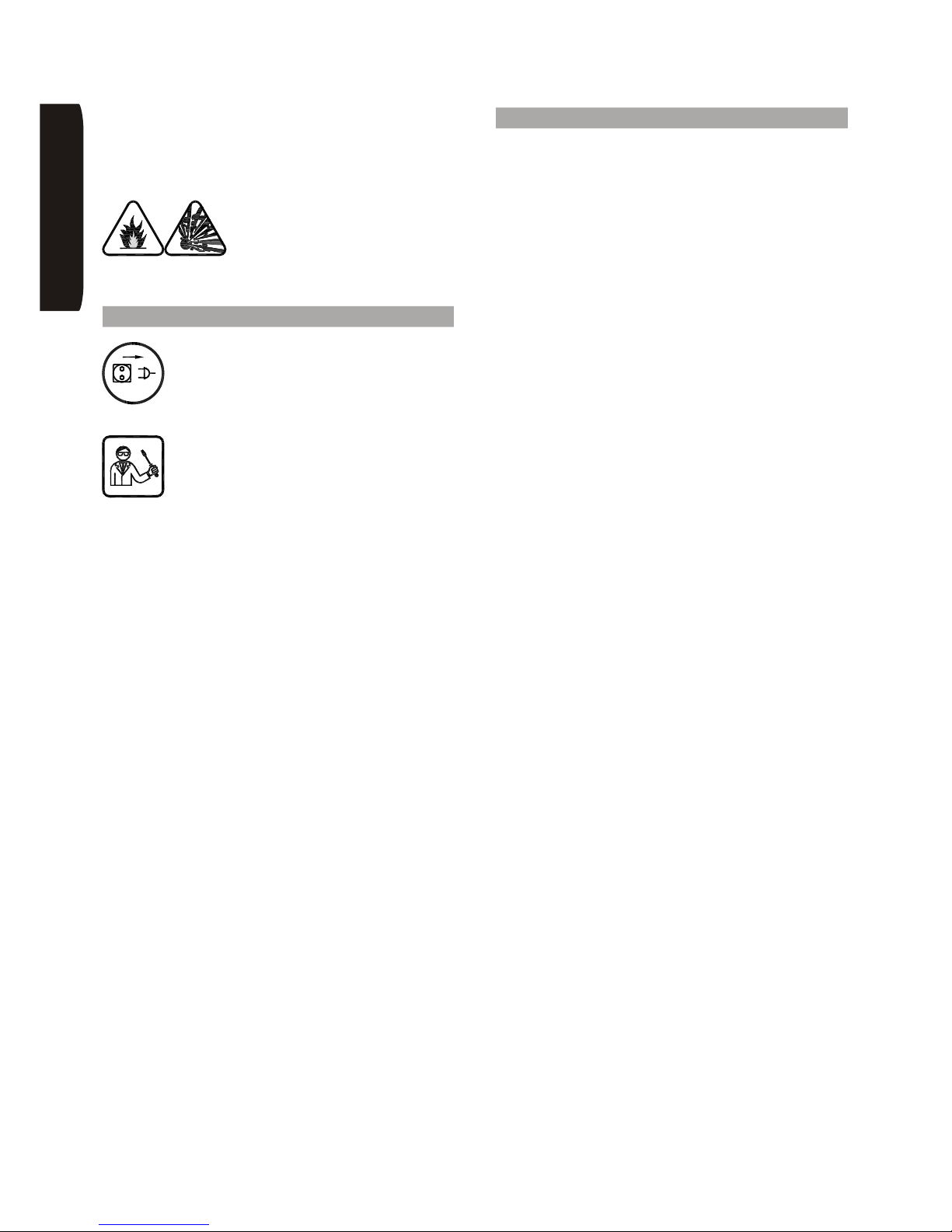
E’ severamente vietato eseguire
saldature su recipienti di
combustibile contenenti materiale
infiammabile, anche se vuoti.
Pericolo di incendio e/o esplosione!
7 Manutenzione
Ogni intervento di riparazione o di
sostituzione di parti dell’impianto deve
essere eseguito da personale qualificato e
idoneo ad operare nel settore
dell’impiantistica elettromeccanica.
All’operatore è consentito asportare i
pannelli della carrozzeria (non prima di
aver sconnesso il generatore dalla linea
di alimentazione) solamente per asportare i
depositi di polvere e di sporcizia aspirati
all’interno.
Questa operazione deve essere eseguita con un getto
di aria compressa, priva di olio e umidità, almeno ogni
tre mesi. E’ consigliabile aumentare la frequenza di tali
interventi se si lavora in ambienti molto polverosi.
Giornalmente, inoltre, verificare che vicino al gruppo
traino non si siano formati depositi di polvere o siano
rimasti pezzi di filo tagliati. In tal caso pulire con cura in
modo da evitare contatti elettrici con la carcassa del
carrello.
8 Compatibilità elettromagnetica (EMC)
Gli impianti per saldatura INE sono apparati da usarsi
esclusivamente in ambiente industriale (CLASSE A del
CISPR11). Il loro impiego in ambienti diversi (ad
esempio quello domestico) può comportare dei
problemi di compatibilità con apparecchi operanti nelle
vicinanze (radio, telefoni, computer, ecc.).
E’ responsabilità dell’utilizzatore l’installazione del
generatore e l’uso dello stesso in ambienti adeguati e
non suscettibili dal punto di vista EMC. Nel valutare gli
ambienti in questione si deve considerare l’eventuale
presenza di:
• linee ed apparecchi telefonici
• apparecchi radiotelevisivi riceventi e trasmittenti
• computer ed attrezzature di comando
• attrezzature di sicurezza
• strumenti di misura
Particolare attenzione devono prestare le persone
portatrici di stimolatori cardiaci e di analoghi apparecchi
bioelettronici che sono potenzialmente suscettibili ai
campi elettromagnetici. A queste persone si
raccomanda vivamente di non avvicinarsi ai luoghi in
cui si svolgono i processi di saldatura.
Nell’eventualità si verificassero delle perturbazioni
elettromagnetiche la responsabilità di risolvere la
situazione spetta all’utente, al quale la INE come
costruttore offre la più completa assistenza.
Per ulteriori informazioni si rimanda alla normativa EN
60974-10 (in particolare l’allegato A) che regolamenta
la materia nell’ambito CEE.
Questa attrezzatura è conforme alla norma IEC
61000-3-12 a condizione che l’impedenza massima
Zmax ammessa dell’impianto sia inferiore o uguale, al
punto di interfaccia fra l’impianto dell’utilizzatore e
quello pubblico, a:
95 mW (KMP3200)
107 mW (KMP5000)
E’ responsabilità dell’’installatore o dell’utilizzatore
dell’attrezzatura garantire, consultando eventualmente
l’operatore della rete di distribuzione, che l’attrezzatura
sia collegata a un’alimentazione con impedenza
corretta.
ONAILATI
Page 7
Page 5
INE S.p.A. Via Facca, 10 - 35013 Cittadella - PADOVA - ITALIA Tel. 049/9481111 - Fax 049/9400249 - [email protected] - www.ine.it
9 Saldatura MMA: procedimenti e dati
tecnici
Il procedimento MMA è il più semplice tra quelli
utilizzabili per la saldatura ad arco elettrico e si realizza
avvalendosi solo di un generatore di corrente collegato
ad una pinza portaelettrodo.
L’elettrodo è costituito da due parti fondamentali:
• L’ANIMA: è formata dello stesso materiale del pezzo
da saldare (alluminio, ferro, rame, acciaio inox) ed
ha la funzione di apportare materiale nel giunto.
• Il RIVESTIMENTO: è costituito da varie sostanze
minerali ed organiche miscelate fra loro. Le sue
funzioni sono:
A) Protezione gassosa
Una parte del rivestimento volatizza alla temperatura
dell’arco creando una colonna di gas ionizzato che
protegge il metallo fuso dall’ossidazione.
B) Apporto di elementi leganti e scorificanti
Una parte del rivestimento fonde e apporta nel
bagno di fusione degli elementi che si combinano col
materiale base e formano la scoria.
Si può affermare che la modalità di fusione e le
caratteristiche del deposito di ciascun elettrodo
derivano sia dal tipo di rivestimento che dal materiale
dell’anima.
I principali tipi di rivestimento degli elettrodi sono:
Rivestimenti acidi
Questi rivestimenti danno luogo ad una buona
saldabilità e possono essere impiegati in corrente
alternata o in corrente continua con pinza collegata al
polo negativo (polarità diretta). Il bagno di fusione è
molto fluido per cui sono adatti essenzialmente per
saldature in piano.
Rivestimenti al rutilo
Questi rivestimenti danno al cordone un’estrema
esteticità per cui il loro impiego è largamente diffuso. Si
possono saldare in corrente alternata ed in corrente
continua con entrambe le polarità.
Rivestimenti basici
Sono utilizzati essenzialmente per saldature che
necessitano di elevate caratteristiche meccaniche. Si
usano, generalmente, in corrente continua con
l’elettrodo al polo positivo (polarità inversa) anche se
esistono degli elettrodi basici per corrente alternata. E’
consigliabile tenerli in un ambiente privo di umidità.
Rivestimenti cellulosici
Sono elettrodi che si usano in corrente continua
collegandoli al positivo (polarità inversa). Sono
utilizzati, normalmente, per la saldatura di tubi data la
viscosità del bagno di saldatura e la forte penetrazione.
Richiedono, però, generatori di corrente con adeguate
proprietà.
Il processo di saldatura ad elettrodo è caratterizzato dai
seguenti parametri:
A) Corrente di saldatura
Questo parametro varia a seconda del tipo e del
diametro dell’elettrodo oltre che dalla posizione di
saldatura. E’ praticamente la variabile principale:
determina la penetrazione, il volume del metallo e la
larghezza del cordone depositato.
B) Tensione d’arco
Questo parametro dipende essenzialmente dalla
distanza tra la punta dell’elettrodo e il pezzo da saldare.
Aumentando questa distanza diminuisce la
penetrazione, il cordone si allarga e possono comparire
delle proiezioni di materiale fuso (spruzzi).
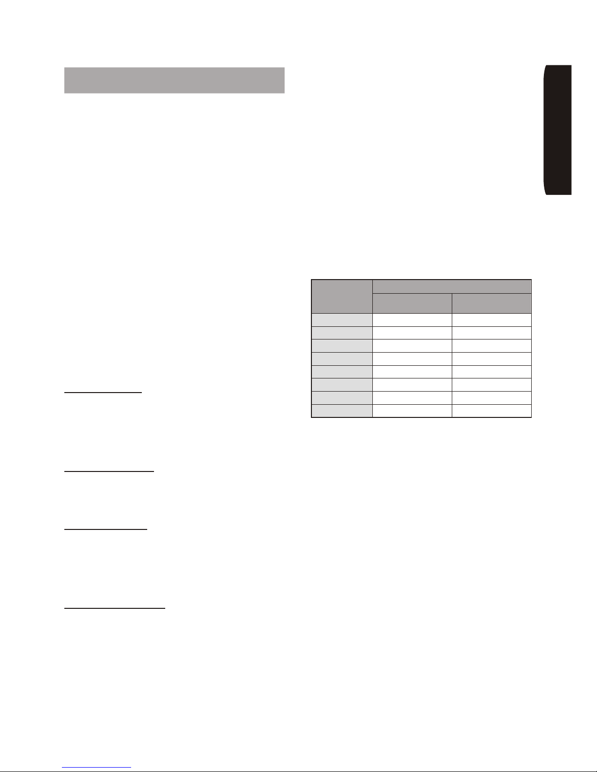
Nella tabella seguente vengono date, a titolo indicativo,
le correnti da utilizzare con i vari diametri d’elettrodo per
saldature su acciaio al carbonio:
Nella scelta del diametro dell’elettrodo si può prendere,
come parametro, la dimensione più vicina allo spessore
del materiale da saldare.
Quando la saldatura viene eseguita in posizione non
orizzontale, il bagno di fusione tende fluire per gravità.
E’ preferibile, in questi casi, l’impiego di elettrodi di
piccolo diametro e di effettuare la saldatura in più
passate successive. Può essere consigliabile,
specialmente per spessori superiori ai 3 mm, preparare
adeguatamente i lembi da saldare eseguendo un
cianfrino a ‘V’ oppure a ‘X’. In questo caso, l’operazione
di saldatura consiste, oltre alla giunzione dei pezzi,
anche nel riempimento del cianfrino (si consiglia di
utilizzare nella prima passata un elettrodo sottile per
evitare di forare i pezzi stessi).
L’arco elettrico si stabilisce sfregando la punta
dell’elettrodo sul pezzo da saldare e ritraendo,
rapidamente, la bacchetta fino alla distanza di
accensione dell’arco. Un movimento troppo rapido, con
eccessivo distacco, provoca lo spegnimento dell’arco,
mentre, al contrario, un movimento lento può causare il
corto circuito delle parti; in quest’ultimo caso uno
strappo laterale permette il distacco dell’elettrodo dal
pezzo.
Diametro
elettrodo
(mm)
Corrente (A)
Minima Massima
1,6 25 50
2 40 70
2,5 60 110
3,25 80 150
4 100 180
5 140 250
6 190 340
7 240 430
ONAILATI
Page 8
Page 6
INE S.p.A. Via Facca, 10 - 35013 Cittadella - PADOVA - ITALIA Tel. 049/9481111 - Fax 049/9400249 - [email protected] - www.ine.it
Per migliorare l’accensione dell’arco è utile che il
generatore fornisca un picco iniziale di corrente rispetto
a quella impostata; questo accorgimento viene
denominato ‘Hot start’.
Una volta instaurato l’arco inizia la fusione della parte
centrale dell’anima dell’elettrodo che si deposita sotto
forma di gocce sul pezzo da saldare. Il rivestimento
esterno dell’elettrodo fornisce, consumandosi, il gas
protettivo necessario per una saldatura di buona qualità
(come spiegato precedentemente).
L’operatore, durante la saldatura, accidentalmente
potrebbe avvicinare troppo l’elettrodo al bagno
realizzando un corto circuito e il conseguente
spegnimento dell’arco. In questo caso il generatore
aumenta momentaneamente la corrente di saldatura
erogata fino al termine del corto circuito; tale
accorgimento viene denominato ‘Arc Force’.
Le tecniche riguardanti l’esecuzione dei giunti sono
numerose e, di conseguenza, possiamo dare solo delle
indicazioni di massima su come operare.
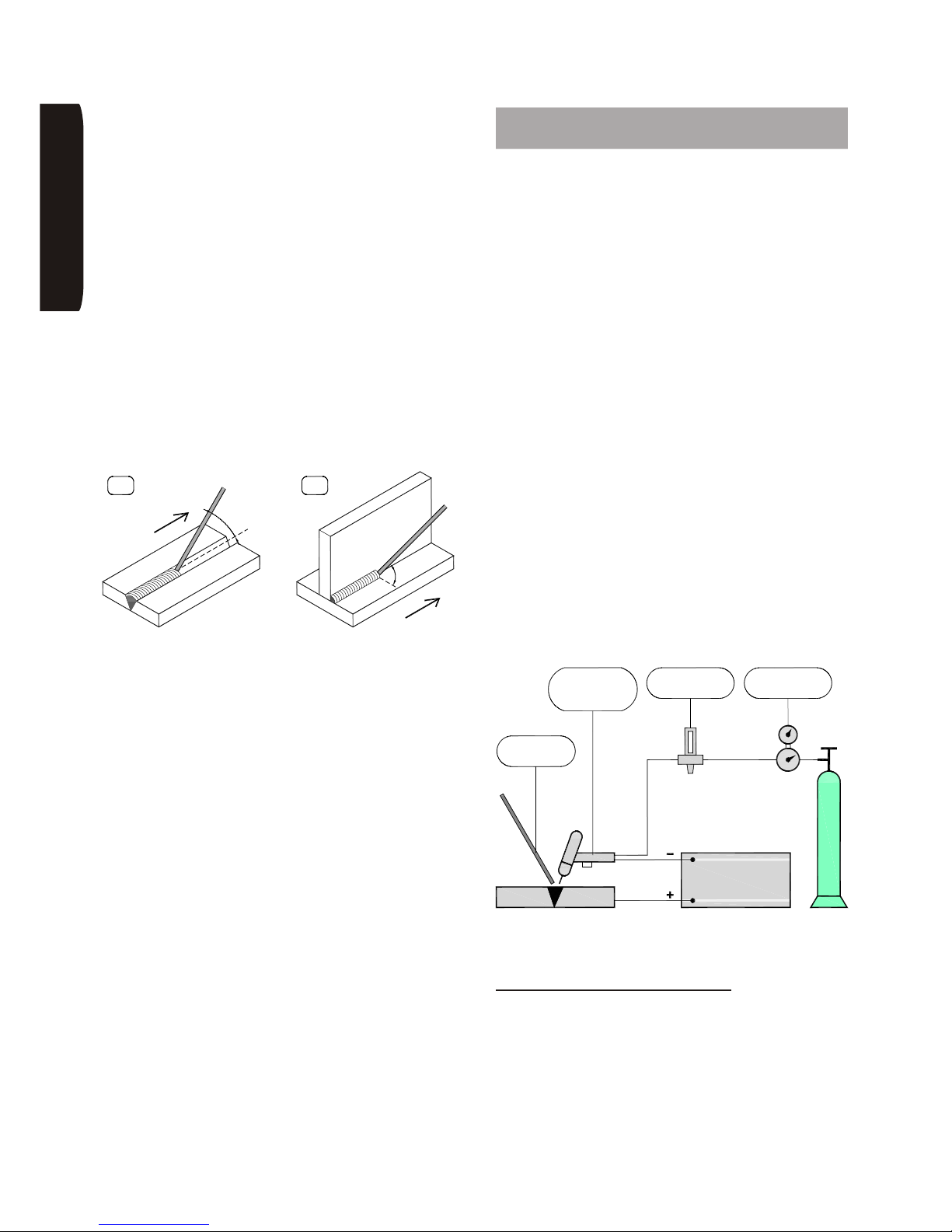
Nelle figure qui sopra vengono mostrati due esempi
tipici di saldatura in piano di un giunto testa-testa (fig.A)
e di un giunto a ‘T’ (fig.B). L’angolo d’inclinazione
dell’elettrodo varia a seconda del numero delle passate
e il movimento dello stesso è un’oscillazione
trasversale con brevi fermate ai lati del cordone in
modo da evitare un eccessivo accumulo di materiale
d’apporto al centro.
La saldatura mediante elettrodi rivestiti impone
l’asportazione della scoria successivamente ad ogni
passata. Tale operazione si rivela di fondamentale
importanza per ottenere un giunto uniforme e privo
d’intervento. L’asportazione si effettua mediante un
piccolo martello o, se la scoria è friabile, attraverso una
spazzola metallica.
10 Saldatura TIG: procedimenti e dati
tecnici
Il procedimento di saldatura TIG è realizzato mediante
un arco elettrico sostenuto da un elettrodo di materiale
non fusibile di tungsteno puro o legato. A differenza
degli altri procedimenti (MMA e MIG), quindi, l’elettrodo
non costituisce il materiale d’apporto della giunzione da
effettuare. Tale apporto può essere eseguito
dall’operatore, generalmente per mezzo di apposite
bacchette realizzate con materiale della stessa natura
di quello del pezzo da saldare. Un’atmosfera di gas
inerte (Argon oppure Elio) provvede alla protezione
dell’arco. Possibilmente l’elettrodo non deve entrare a
contatto con il materiale da saldare, pertanto il
generatore dovrebbe essere dotato di un accenditore
H.F. che genera l’accensione dell’arco mediante
scarica elettrica ad alta tensione (evitando, quindi il
contatto, con il pezzo). E’, tuttavia, possibile anche la
partenza senza l’accensione mediante H.F. Questo tipo
di partenza si chiama ‘Lift-arc’ ed è impiegabile
solamente se il generatore è in grado di regolare una
corrente di cortocircuito iniziale molto bassa (qualche
ampere) che permetta di evitare il consumo
dell’elettrodo. Questa caratteristica è un’esclusiva dei
generatori ad inverter.
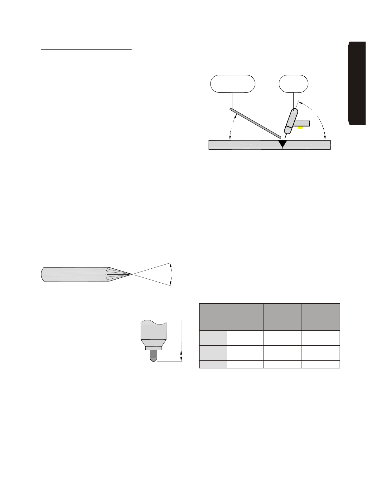
L’impianto di saldatura TIG è formato da:
- una sorgente di corrente continua o alternata
- una torcia dotata di elettrodo infusibile
- una bombola di gas inerte dotata di riduttore di
pressione e flussometro
Si possono avere diverse tipologie di saldatura TIG, in
funzione del tipo di materiale e di apporto termico
richiesto. Vengono, di seguito, illustrate le principali.
Corrente continua, polarità diretta
Questo procedimento prevede che la torcia sia
collegata al morsetto negativo del generatore e la
massa al positivo. La maggior parte del calore (circa il
70%) è assorbita e dispersa dal pezzo da saldare
ottenendo così una forte penetrazione. Questa polarità
si adatta a tutti i metalli, escludendo solo l’alluminio, il
magnesio e le loro leghe, ma, per contro, non dà
nessuna azione disossidante.
A B
45°
4
5
°
÷70
°
FLUSSOMETRO
PEZZO
MATERIALE
D'APPORTO
ELETTRODO
INFUSIBILE
TORCIA CON
ARGON O ELIO
GENERATORE
DI PRESSIONE
RIDUTTORE
ONAILATI
Page 9
Page 7
INE S.p.A. Via Facca, 10 - 35013 Cittadella - PADOVA - ITALIA Tel. 049/9481111 - Fax 049/9400249 - [email protected] - www.ine.it
Corrente pulsata, polarità diretta
In linea di principio questo procedimento presenta le
caratteristiche tipiche del precedente a polarità diretta.
Si può solamente aggiungere che l’adozione di una
corrente pulsata permette un migliore controllo del
bagno di saldatura in condizioni particolarmente difficili
e, specialmente, per le lavorazioni di spessori sottili.
I miglioramenti introdotti da tale tecnica consistono
nella riduzione della zona termicamente alterata, delle
deformazioni, delle cricche e delle inclusioni gassose
all’interno della zona di fusione.
Il procedimento TIG è particolarmente adatto per le
saldature in cui si richiede un’elevata qualità anche
senza la ripresa a rovescio. Il caso tipico è la prima
passata nelle saldature dei tubi. E’ inoltre impiegato nei
casi in cui si richiede una gradevole estetica della
saldatura senza ulteriori lavorazioni (per esempio
smerigliatura). Essendo il procedimento impegnativo,
rispetto agli altri, si richiede un’attenta pulizia dei lembi
in generale ed una loro adeguata preparazione: è
consigliato di eseguire una cianfrinatura a ‘V’ per
spessori superiori ai 3 mm.
Per le saldature di rame ed alluminio, data la fluidità di
questi metalli allo stato fuso, è consigliabile l’uso di un
supporto (per esempio di acciaio inox) al rovescio.
Gli elettrodi prima dell’utilizzo, per saldature in corrente
con polarità diretta, devono essere appuntiti utilizzando
una smerigliatrice dedicata allo scopo.
Come si vede dalla figura l’angolo può essere molto
acuto per basse correnti (30° fino a 30-40A), mentre
dev’essere ampio per correnti elevate (maggiore di 90°
per correnti superiori a 200A).
L’elettrodo deve venire fissato al
portaelettrodo considerando che, la
sporgenza massima dall’ugello
dev’essere di 6-9 mm come mostrato
in figura (valori maggiori possono
essere utilizzati solo per le saldature
ad angolo interno).
Per ottenere i migliori risultati, con questo tipo di
saldatura, si devono tenere la torcia e la bacchetta del
materiale d’apporto in maniera conforme al sistema
illustrato nella figura seguente.
Saldando invece con polarità variabile o inversa, a
causa dell’elevato calore che si sviluppa sull’elettrodo,
è necessario che quest’ultimo presenti un’estrema
arrotondata contrariamente al caso precedente. Se
durante la saldatura si nota che l’elettrodo fonde
(l’estremità assume la forma di goccia) si deve
procedere alla sostituzione dello stesso con uno di
diametro superiore, oppure, nel caso di saldatura a
polarità variabile, si deve agire sul bilanciamento
dell’onda riducendo la polarizzazione positiva della
corrente intorno al 20%.
Relativamente al materiale da saldare è consigliabile
adoperare i seguenti elettrodi:
• tungsteno toriato a 2% (colore rosso) per acciaio,
leghe di acciaio, nichel, rame e titanio
• tungsteno puro (colore verde) oppure tungsteno con
zirconio (colore bianco) per alluminio e magnesio
In tabella sono riportate le gamme di amperaggi
utilizzabili in funzione del tipo di elettrodo e della
polarità di corrente utilizzata.
Come materiale d’apporto devono venire utilizzate le
apposite bacchette presenti in commercio. Queste
bacchette sono costituite dello stesso materiale di base
di quello da saldare e nel caso del rame e dell’alluminio
con piccole percentuali (inferiori al 10%) di agenti
antiossidanti quali il silicio o il magnesio.
30°÷120°
6÷9 mm
TORCIA
MATERIALE
PEZZO DA SALDARE
ß<30°
D'APPORTO
60°÷80°
ONAILATI
Diametro
elettrodo
(mm)
Corrente
continua
Polarità
diretta
Corrente
continua
Polarità
inversa
Corrente
alternata
Polarità
variabile
1 10÷70 10÷15 10÷50
1,6 60÷150 10÷20 40÷100
2,4 100÷250 15÷30 80÷150
3,2 200÷400 25÷50 130÷230
4,8 350÷800 45÷80 200÷320
Page 10
Page 8
INE S.p.A. Via Facca, 10 - 35013 Cittadella - PADOVA - ITALIA Tel. 049/9481111 - Fax 049/9400249 - [email protected] - www.ine.it
Come gas di protezione, per ragioni di costo, si utilizza
più comunemente l’argon. L’impiego dell’elio o di
miscele argon/elio possono essere impiegate
specialmente per saldature di grossi spessori, allo
scopo di favorire la penetrazione del bagno e di
aumentare la velocità di saldatura.
Le portate di gas comunemente variano, all’aumentare
della corrente, da 7 a 12 l/min per l’argon e da 14 a 24
l/min per l’elio.
Per evitare ossidazioni è opportuno regolare il post-gas
in modo che la saldatura e l’elettrodo abbiano il tempo
di raffreddarsi prima di essere esposti all’ossigeno
dell’aria. Questo tempo è dell’ordine di qualche
secondo.
11 Saldatura MIG/MAG: procedimenti e
dati tecnici
Il procedimento MIG/MAG utilizza, per la saldatura di
acciai comuni e bassolegati, un filo di acciaio ramato e
un gas attivo (CO2 oppure Argon-CO2).
Per la saldatura di acciai INOX è necessario usare il filo
di materiale corrispondente a quello da saldare e il gas
deve essere una miscela Argon-CO2-O2.
Per saldare l’alluminio si deve impiegare il tipo di filo
compatibile al materiale e l’Argon puro come gas; è
consigliabile inoltre che la guaina della torcia sia in
teflon.
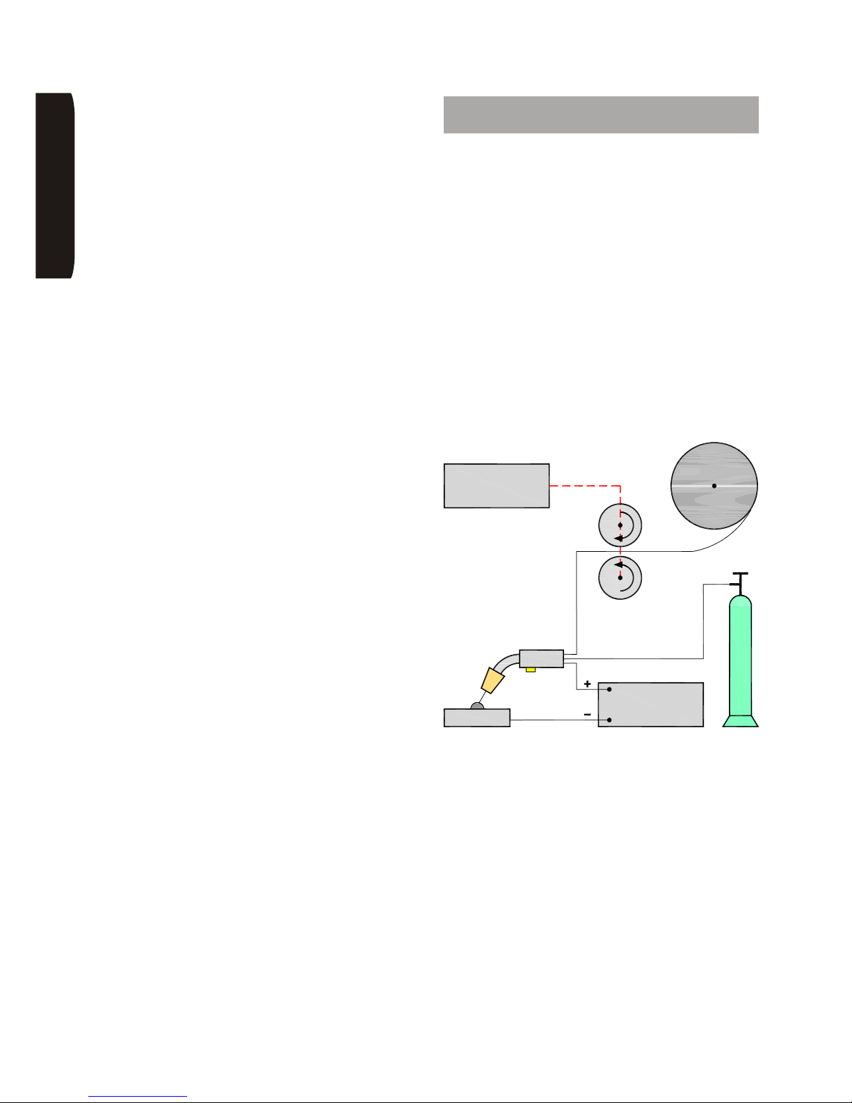
L’impianto di saldatura MIG/MAG è formato dalla
presenza di:
• una sorgente di corrente continua (saldatrice)
• un trainafilo
• una torcia con cavo
• una bombola di gas con riduttore e flussometro
Durante il processo di saldatura la torcia viene condotta
manualmente dal saldatore lungo la giunzione da
realizzare mentre il filo, fatto avanzare dal trainafilo,
fonde e forma il cordone di saldatura.
E’ opportuno iniziare a saldare con l’assistenza di un
esperto.
E’ necessario, infatti, un minimo di apprendimento per :
• la regolazione dei parametri
• evitare la generazione degli spruzzi
La regolazione dei parametri consiste nell’individuare il
giusto equilibrio di tensione e velocità del filo necessari
per effettuare una corretta saldatura.
BOBINA FILO
GENERATORE
PEZZO
FILO
ALIMENTATORE
GAS
ONAILATI
Page 11
Page 9
INE S.p.A. Via Facca, 10 - 35013 Cittadella - PADOVA - ITALIA Tel. 049/9481111 - Fax 049/9400249 - [email protected] - www.ine.it
Per evitare gli spruzzi occorre orientare in maniera
ottimale la torcia rispetto al cordone di saldatura da
effettuare. A questo proposito è necessario inoltre
evitare il manifestarsi di un particolare fenomeno che si
manifesta come una deviazione dell’arco dovuto alle
forze elettromagnetiche in gioco: il soffio magnetico.
Questo fenomeno si ha principalmente nelle saldature
ad angolo e negli spigoli interni di pezzi scatolati. Per
ridurlo può essere utile orientare la torcia in senso
opposto alla deviazione dell’arco e scegliere in modo
opportuno il punto di collegamento del morsetto di
massa.
Particolare attenzione deve essere posta nella
saldatura di spessori sottili oppure nella prima passata
di giunti smussati, in quanto esiste il pericolo di
sfondare il materiale. Si consiglia in questi casi di
saldare con bassi valori di corrente (short-arc).
Da un punto di vista fisico esistono due processi di
fusione del metallo di apporto e del suo trasferimento
dal filo al bagno di saldatura:
SHORT-ARC (arco corto)
SPRAY-ARC (arco a spruzzo)
Il primo processo si ha per tensioni d’arco inferiori a 24V
e per intensità di correnti relativamente basse (inferiori
a 200 A/mmq). In questo procedimento la fusione del
filo avviene per corto-circuito in quanto il filo stesso
entra in contatto con il bagno di saldatura provocando il
trasferimento a gocce del materiale. Visivamente l’arco
si presenta corto ed è consigliabile mantenere il tubetto
porta-corrente sporgente di 2-3 mm rispetto all’ugello
del gas.
Questo procedimento è impiegato in qualsiasi
posizione di saldatura (piana, angolare, verticale) ed in
generale dove sono richiesti bassi valori di corrente allo
scopo di evitare deformazioni e sfondamenti: spessori
sottili, prime passate ecc.
Lo spray-arc è, invece, un processo che richiede valori
più elevati di tensione e corrente e nel quale la fusione
del metallo è accompagnata dalla polverizzazione dello
stesso in piccole gocce e quindi dal suo trasferimento
verso il bagno di saldatura.
Visivamente l’arco presenta una certa lunghezza e la
sua luminosità è maggiore. E’ consigliabile mantenere il
tubetto porta-corrente arretrato rispetto all’ugello del
gas (da 5 a 10 mm, all’aumentare della corrente
erogata).
Questo procedimento è impiegato solamente per le
saldature in piano di spessori elevati (maggiori di 4 mm)
ove è necessaria una elevata velocità di deposito
materiale. Da osservare infine che maggiore è la
lunghezza dell’arco (corrispondente ad una maggiore
tensione V) e, a parità di corrente A, maggiore risultano
la larghezza e l’appiattimento del cordone di saldatura.
In altri termini alzando la tensione si allarga il “cono di
deposito” del materiale.
Una annotazione particolare merita, a questo punto, il
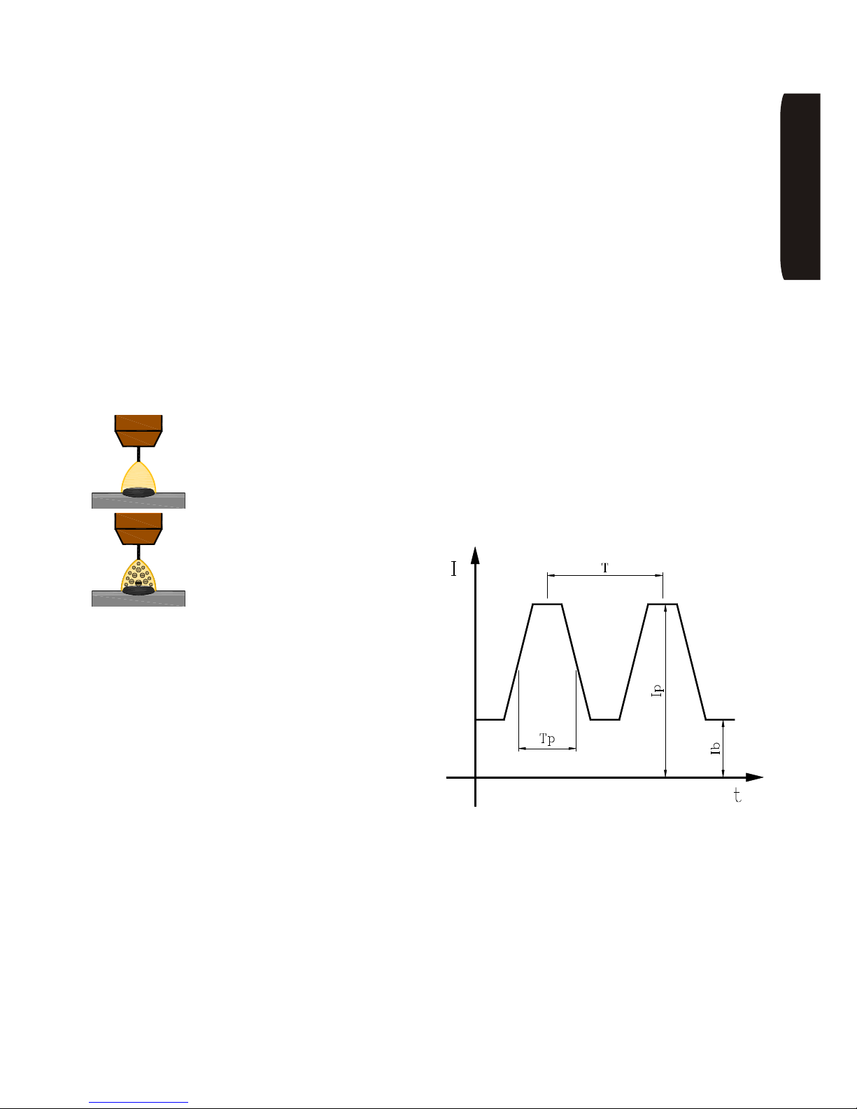
procedimento di saldatura MIG/MAG ad arco pulsato.
Esso è caratterizzato dall’avere l’andamento di
corrente non costante, ma ad impulsi di valore elevato.
Fra un impulso e l’altro è erogato un valore di corrente
minimo necessario solamente a tener acceso l’arco
senza fondere il materiale. In questo modo è possibile
abbassare il valore medio della corrente di saldatura
pur saldando in spray-arc. Si possono così ottenere i
vantaggi di quest’ultimo procedimento (alta qualità
della saldatura per effetto della polverizzazione del
materiale fuso e la possibilità di variare la larghezza del
cordone) anche a bassi valori di corrente tipici dei
piccoli spessori e delle saldature non in piano.
Per completezza riportiamo, inoltre, il concetto di
sinergia. In un impianto sinergico il legame
tensione-corrente di saldatura non viene impostato
dall’operatore, al quale è lasciato solamente il compito
di scegliere la potenza dell’arco con cui intende
saldare. Si evita così la perdita di tempo per la
regolazione dei parametri e un funzionamento ottimale
relativamente alla minimizzazione degli spruzzi.
ONAILATI
Page 12
Page 10
INE S.p.A. Via Facca, 10 - 35013 Cittadella - PADOVA - ITALIA Tel. 049/9481111 - Fax 049/9400249 - [email protected] - www.ine.it
12 Installazione e predisposizione per il
funzionamento
Nell’installazione della macchina è
necessario osservare scrupolosamente
quanto prescritto nei paragrafi precedenti
relativi alla sicurezza.
Essa consiste essenzialmente nel collegamento del
carrello trainafilo al generatore, mediante l’apposita
prolunga e del collegamento del generatore alla rete.
Collegare il cavo di alimentazione ad una spina con
adeguata portata di corrente ed inserire i fusibili di
linea ritardati con un valore nominale adeguato, come
specificato sulla tabella DATI TECNICI (pagina 60).
Fare, inoltre, molta attenzione che il filo giallo-verde,
corrispondente al collegamento di terra, venga
effettivamente e correttamente collegato all’impianto di
messa a terra (per garantire la protezione
dell’utilizzatore stesso).
Per la messa in opera della macchina procedere in
questo modo:
• Posizionare la macchina in modo tale che la
ventilazione per il raffreddamento interno non possa
venire compromessa. Per questo motivo si devono
evitare luoghi umidi e si devono avere almeno 0,5 m
di distanza da pareti, ripari o altro.
Per la saldatura a filo (MIG/MAG):
• Collegare il carrello al generatore allacciando il
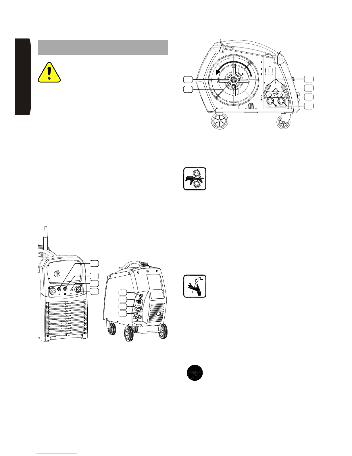
fascio cavi agli attacchi ‘A1’ e ‘C2’ della macchina e
alle prese posteriori del carrello trainafilo ‘A4’, ‘C4’,
‘G3’ facendo attenzione al loro completo fissaggio.
• Il tubo gas del fascio cavi va allacciato direttamente
all’attacco del riduttore di pressione della bombola.
• Nel caso la macchina sia dotata di gruppo di
raffreddamento collegare anche gli innesti rapidi ‘H1’
per l’acqua facendo riferimento ai colori degli stessi.
• Posizionare la bobina di filo nell’apposito rocchetto
‘Z1’, osservando il senso di svolgimento del filo.
Alzare il ponte premifilo ‘V2’. Applicare il rullo
trascinafilo ‘V3’ corrispondente al diametro del filo
impiegato.
Fare attenzione al corretto fissaggio della
bobina del filo. PERICOLO! Non
intervenire sulle ruote dentate del motore
trainafilo quando questo è in movimento.
• Richiudere il premifilo regolando opportunamente la
pressione ‘V1’. Far avanzare il filo premendo
l’apposito pulsante. Regolare l’intensità di frenatura
agendo sulla vite di chiusura dell’aspo ‘Z2’: si deve
chiudere lo stretto necessario affinchè, a bobina
carica, si eviti lo svolgimento del filo all’arresto.
• Allacciare la torcia al relativo attacco torcia ‘A5’
introducendo prima il filo all’entrata della guaina.
Fissare poi la torcia in modo sicuro stringendo a
mano il raccordo. Mantenendo il cavo ben teso far
avanzare il filo premendo il pulsante (vedi paragrafo
14).
Durante questa operazione è assolutamente
vietato posizionarsi con il corpo (e in
particolare con gli occhi) di fronte all’ugello
della torcia per aspettare l’uscita del filo.
• Chiudere il pannello mobile del trainafilo.
• Collegare il cavo massa alla boccola del negativo
‘A3’ e ad un punto adeguatamente pulito del pezzo
da saldare.
• Allacciare il tubo gas al riduttore di pressione, il quale
deve prima essere applicato seguendo
scrupolosamente le istruzioni per la sua
installazione.
Nota tecnica: nel caso si utilizzi filo animato,
che ha la protezione del bagno di saldatura
al suo interno, il gas non è necessario ed
inoltre, per ottenere i migliori risultati, si deve
utilizzare la polarità di saldatura consigliata
dal produttore del filo (normalmente opposta a quella
per il filo tradizionale). Per poter utilizzare la polarità
negativa sul filo è disponibile il kit opzionale
PFCS0400015.
Z1
Z2
A5
V3
V1
V2
G1
A1
C2
C1
optional
C4
H1
A4
G3
i
ONAILATI
Page 13
Page 11
INE S.p.A. Via Facca, 10 - 35013 Cittadella - PADOVA - ITALIA Tel. 049/9481111 - Fax 049/9400249 - [email protected] - www.ine.it
Per la saldatura in TIG DC:
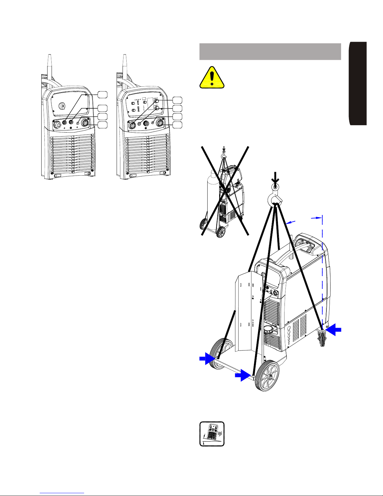
• Allacciare il tubo del gas proveniente dalla bombola
(dotata di flussometro e di regolatore di pressione
precedentemente installato) all’attacco posteriore
della macchina ‘G1’; quindi collegare la torcia alla
boccola posta sul frontale ‘A3’. Fissare il tubo del gas
della torcia e il connettore per il comando del
pulsante torcia sugli innesti ‘G2’ e ‘C3’ posti sul
frontale.
• Collegare il cavo massa alla boccola ‘A2’ del
generatore e ad un punto adeguatamente pulito del
pezzo da saldare.
Per la saldatura ad elettrodo (MMA):
• Collegare la pinza portaelettrodo alla boccola
(positiva ‘A2’ o negativa ‘A3’) richiesta dal tipo di
elettrodo.
• Collegare il cavo massa alla boccola libera del
generatore e ad un punto adeguatamente pulito del
pezzo da saldare.
13 Sollevamento: indicazioni e
precauzioni
Per sollevare la macchina utilizzare
esclusivamente i 4 FORI presenti sulla
base del carrello portageneratore PR8.
Prestare attenzione affinchè i cavi di sollevamento
formino un angolo piccolo rispetto alla verticale. Tutte le
parti mobili presenti sulla macchina - es. bombola del
gas, prolunga generatore-carrello, carrello
trainafilo, torce, cavi massa, ecc. - vanno rimosse per
evitare cadute incontrollabili di tutto o di parte del carico
sollevato.
La macchina va posizionata in un piano
solido e stabile adeguato al peso
dell’impianto. L’inclinazione massima
consentita è di 10°.
MAX
15°
ONAILATI
A3
G2
C3
A2
G1
A1
C2
C1
optional
Page 14
Page 12
INE S.p.A. Via Facca, 10 - 35013 Cittadella - PADOVA - ITALIA Tel. 049/9481111 - Fax 049/9400249 - [email protected] - www.ine.it
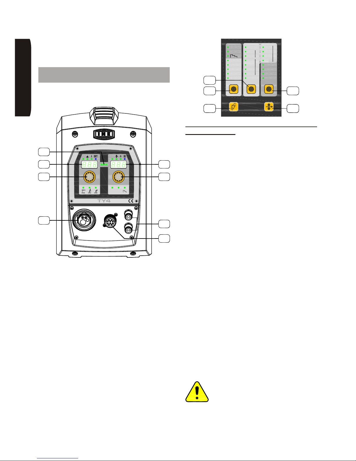
Le funzionalità e i comandi sono impostabili sia dalla
macchina che dal carrello trainafilo in modo
indipendente ed intercambiabile.
14 Impostazioni tramite interfaccia
carrello TY4
Con riferimento alla figura seguente sono di seguito
descritti i comandi e visualizzazioni.
L’accensione della macchina avviene ruotando in
posizione ON l’interruttore generale posto sul retro del
generatore. L’avvenuta accensione è segnalata dalla
barra led ‘L5’ di colore verde.
La barra led ‘L5’, inoltre, ha le seguenti funzioni:
• di colore giallo indica l’intervento dei dispositivi di
protezione e il display ‘D3’ e ‘D4’ indicano il tipo di
protezione intervenuta (vedi paragrafo ‘Descrizione
intervento allarmi’)
• di colore fucsia indica che si va ad effettuare una
saldatura in modalità ‘GLOBULAR’
• di colore rosso indica la presenza di tensione in
uscita. In elettrodo è sempre accesa mentre in TIG e
in MIG/MAG segue l’andamento del ciclo di
saldatura
• di colore blu lampeggiante, dopo la saldatura, indica
la funzionalità HOLD che mantiene le misure di
corrente e tensione visualizzate per 5 secondi prima
di tornare all’interfaccia di impostazione
14.1 Impostazioni per la saldatura ad
elettrodo (MMA)
Premere il pulsante ‘T1’ e tenerlo premuto. Fare
scorrere i led fino all’accensione del led relativo al
processo di saldatura MMA. Quindi rilasciare il tasto.
Attenzione: in uscita al generatore ci sarà la tensione a
vuoto.
Con il selettore ‘E7’ è possibile impostare la corrente di
saldatura che viene visualizzata sul display ‘D4’. Sul
display ‘D3’ viene visualizzata la misura della tensione
in uscita.
Durante la saldatura ‘D4’ visualizzerà la misura effettiva
della corrente erogata.
Tramite il menu ‘SET’, si possono impostare anche i
seguenti parametri:
Hotstart HOT: incremento percentuale della corrente
in partenza; facilita l’innesco dell’arco elettrico.
Arcforce ARC: incremento percentuale della corrente
durante la saldatura al verificarsi di cortocircuiti tra
elettrodo e pezzo; aiuta ad evitare lo spegnimento
dell’arco.
Per poter modificare questi parametri si deve agire in
questo modo:
• Premere il selettore ‘E6’ per due secondi; il led blu
‘SET’ si accende.
• Ruotare il selettore ‘E6’ per selezionare il parametro
da modificare visualizzato su ‘D3’.
• Ruotare il selettore ‘E7’ per modificarne il valore su
‘D4’.
• Ruotare il selettore ‘E6’ per selezionare un altro
parametro oppure premere ‘E6’ per uscire.
Attenzione: scegliendo la saldatura MMA è
importante, per evitare rischi e situazioni di
pericolo, controllare la posizione della torcia
MIG/MAG in quanto risulterà energizzata al
potenziale del positivo. (Evitare quindi il
contatto con il pezzo in lavorazione ed il circuito di
protezione di terra).
TY4TY4
AV
2T 4T
C6
E7
H2
D4
E6
A5
D3
L5
MIG
Argon
AlMg
ø 0.8
MIG P
MIG DP
SPECIAL
CuSi
CuAl
NiCr A rHe
ø 1.2
ø 1.0
ø 1.6
4T
MMA
2T
2
SG2/3
AlSi
CrNi
ArCO
2SG2/3 CO
Basic
CrNi
Metal
Rutil
FCAW - ArCO
2
PRG
KMP
T1
T4
T2
T3
T5
321
ONAILATI
Page 15
Page 13
INE S.p.A. Via Facca, 10 - 35013 Cittadella - PADOVA - ITALIA Tel. 049/9481111 - Fax 049/9400249 - [email protected] - www.ine.it
14.2 Impostazioni per la saldatura
MIG/MAG
Premere il pulsante ‘T1’ e tenerlo premuto. Fare
scorrere i led fino all’accensione del led relativo al
processo di saldatura da utilizzare: MIG, MIG P
(pulsato) o MIG DP (doppio pulsato). Quindi
rilasciare il tasto.
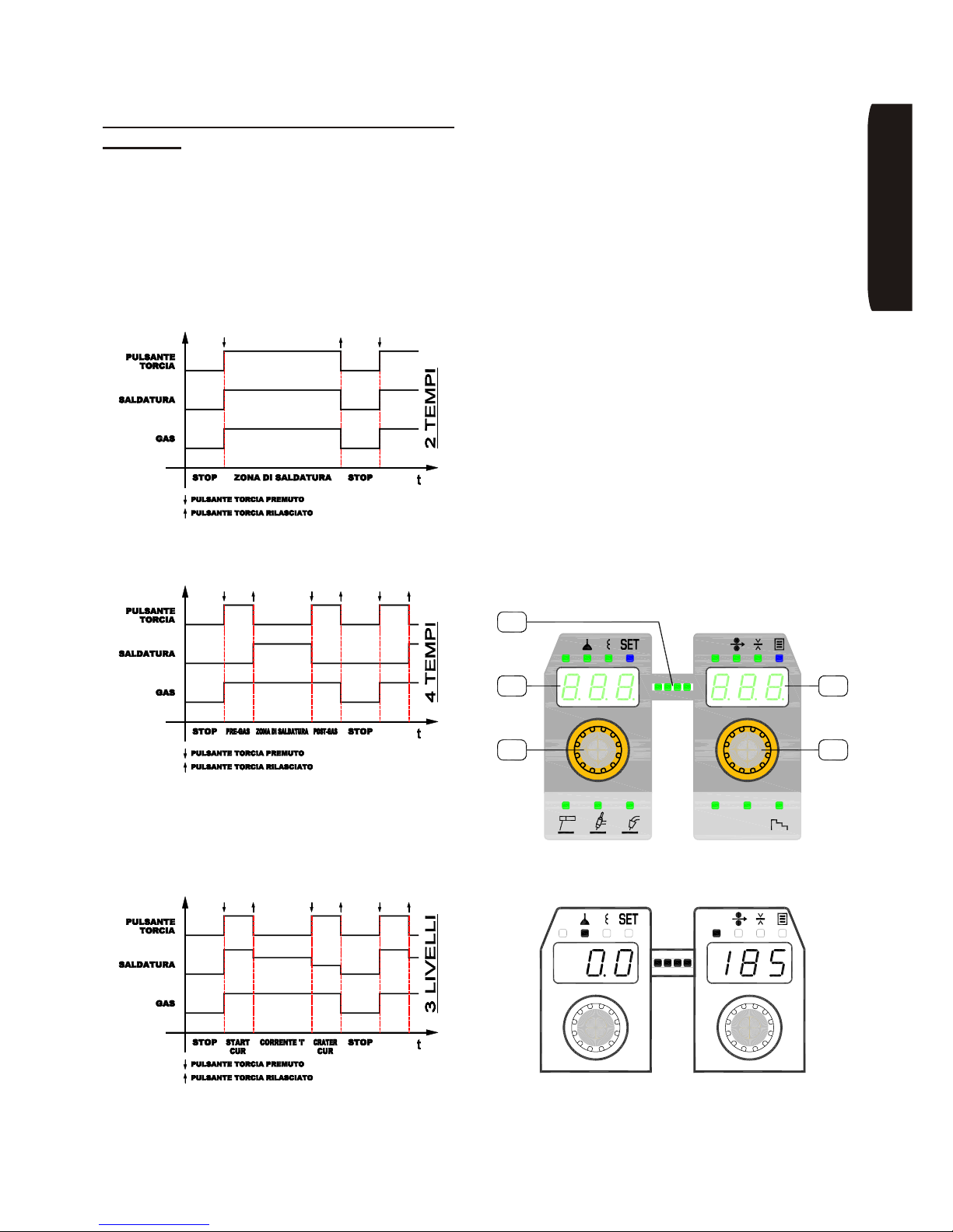
Una pressione veloce di ‘T1’ permette di ciclare tra 2T,
4T e tre livelli; una pressione superiore ai due secondi
permette di cambiare invece il processo di saldatura.
2-tempi: il processo di saldatura inizia nel momento in
cui si preme il pulsante torcia e si arresta al rilascio dello
stesso.
4-tempi: al premere del pulsante torcia il processo di
saldatura inizia con un pre-gas manuale, al suo rilascio
inizia la saldatura vera e propria. Alla successiva
pressione del pulsante torcia la saldatura si arresta
mentre il gas continua a fluire, al suo rilascio si ferma
anche il post-gas manuale.
3-livelli ]: al premere del pulsante torcia il processo
di saldatura inizia al valore di corrente impostato con il
parametro IN1 (vedi spiegazioni successive). Al
rilascio del pulsante la corrente si porta al valore
impostato con ‘E7’. Alla successiva pressione del
pulsante torcia la corrente si porta al valore impostato
con il parametro CRA (vedi spiegazioni successive), al
suo rilascio il processo si arresta.
Con il tasto ‘T2’ si imposta il tipo di filo e il gas di
protezione utilizzato. Con questa operazione viene
selezionata una curva di saldatura sinergica adatta al
materiale scelto (per uscire dai parametri preimpostati
dalla sinergia si rimanda ai paragrafi successivi).
Il tasto ‘T3’ permette la selezione del diametro del filo
utilizzato.
Il tasto ‘T4’ (test-gas) serve per verificare la presenza
del gas per la saldatura, per verificare il corretto
deflusso e per togliere l’aria dal circuito.
Il tasto ‘T5’ serve per far avanzare il filo manualmente,
utilizzato in particolare durante il cambio della bobina.
Premendo ‘T5’ il motore inizierà ad avanzare e con una
rampa di accelerazione di alcuni secondi si porterà alla
velocità del filo di 15 m/min. Durante tutta l’operazione
la barra led ‘L5’ visualizzerà lo sforzo di trascinamento.
Una doppia pressione veloce del tasto ‘T5’ effettua il
recupero del filo invertendo il verso di avanzamento. La
velocità in questo caso risulta impostata al minimo.
Nei processi con sinergia, il selettore ‘E6’ permette di
impostare la correzione dell’altezza dell’arco e
dell’induttanza d’uscita. Per moficare questi valori:
• premere ‘E6’ in sequenza per accendere il led
relativo al parametro da modificare e ruotare ‘E6’ per
cambiarne il valore
V A
2T 4T
E6 E7
L5
D3
D4
V A
ONAILATI
Page 16
Page 14
INE S.p.A. Via Facca, 10 - 35013 Cittadella - PADOVA - ITALIA Tel. 049/9481111 - Fax 049/9400249 - [email protected] - www.ine.it
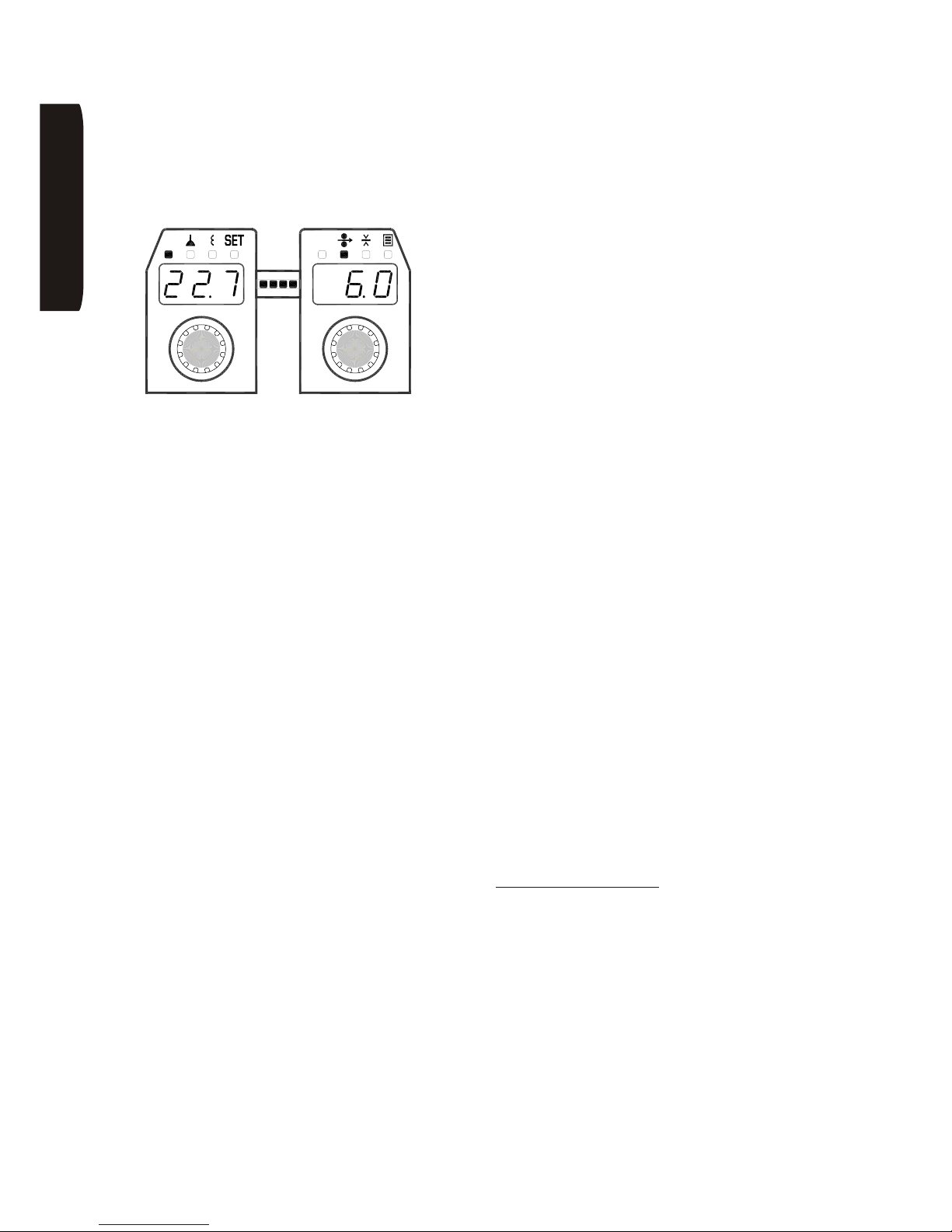
Il parametro tensione ‘V’ può essere impostato
solamente in MIG/MAG non sinergico (vedi funzionalità
SET -> SYN).
Il selettore ‘E7’ permette di impostare la corrente di
saldatura,la velocità del filo e lo spessore del pezzo.
Per moficare questi valori:
• premere ‘E7’ in sequenza per accendere il led
relativo al parametro da modificare e ruotare ‘E7’ per
cambiarne il valore
Tenendo premuto per più di due secondi il selettore ‘E6’
si entra nella modalità SET nel quale si possono
impostare i seguenti parametri avanzati:
• Softstart SOF: al premere del pulsante torcia il filo
avanza lentamente e si porta alla velocità impostata
solamente allo scoccare dell’arco di saldatura. La
sua regolazione è automatica (SYN sul display) o
regolabile da 1 a 100% della velocità impostata del
filo.
• Burnback BUR: regola la lunghezza del filo rispetto
al terminale della torcia. La sua regolazione è
automatica (SYN sul display) o regolabile da 1 a
100%.
• Pregas PRE: tempo di pre gas (secondi).
• Postgas POS: tempo di post gas (secondi).
• Sinergia SYN: consente di attivare (1) o disattivare
(0) la modalità sinergica. Il modo manuale consente
all’utente l’impostazione di tutti i parametri in
maniera del tutto analoga a quanto avviene in
generatori MIG/MAG tradizionali (regolazione di
tensione, induttanza e velocità del filo). Questa
selezione non è presente in MIG P e MIG DP poichè
per una corretta saldatura ad arco pulsato è
necessario il controllo sinergico dei parametri.
Altri parametri sono invece impostabili solo in saldatura
MIG DP (MIG doppio pulsato):
• Double Pulse Frequency DPF: impostazione della
frequenza di doppia pulsazione da un minimo di
0,1Hz ad un massimo di 5Hz; questo parametro
permette di controllare l’alternanza tra i due punti di
saldatura che caratterizzano la doppia pulsazione.
• Double Pulse Duty DPD: impostazione della
simmetria nell’alternanza tra i due punti di saldatura.
Ad esempio, un valore di duty cycle pari a 70 indica
che il punto di saldatura a velocità più elevata ha
durata pari al 70% del periodo di alternanza.
• Double Pulse Offset DPO: i due punti di saldatura
che caratterizzano la doppia pulsazione derivano
dall’applicazione dell’offset, positivo e negativo, al
valore di velocità filo impostata. Ad esempio, con una
velocità filo impostata di 5 m/min ed un offset di 1
m/min, si alterneranno tratti si saldatura a 4 m/min ed
a 6 m/min alla frequenza impostata.
Per poter modificare questi parametri si deve agire in
questo modo:
• Ruotare il selettore ‘E6’ per selezionare il parametro
da modificare.
• Ruotare il selettore ‘E7’ per modificarne il valore.
• Ruotare il selettore ‘E6’ per selezionare
eventualmente un altro parametro oppure premere
‘E6’ per uscire dalla modalità ‘SET’.
Note finali
Attraverso il connettore ‘C6’ posto sul frontale la
macchina può essere controllata tramite comandi a
distanza opzionali. La selezione del controllo remoto è
automatica all’inserimento del connettore e tale rimane
fino allo scollegamento fisico dello stesso.
Memorizzazione programmi e impostazioni
generali
E’ possibile memorizzare le impostazioni personali di
saldatura utilizzando il selettore ‘E7’. Sono
memorizzabili, complessivamente, 100 programmmi.
Dopo aver impostato tutti i parametri desiderati,
accedere al menù memorizzazione dal generatore
premendo il selettore ‘E7’ per due secondi.
Salvare un programma:
• Ruotare la manopola ‘E6’ e selezionare STO
(Store).
• Ruotare ‘E7’ per selezionare la posizione di memoria
desiderata visualizzata sul display ‘D4’.
• Se il numero di memoria selezionato lampeggia,
significa dire che la posizione di memoria è libera. Se
il numero di memoria selezionato è fisso, significa
che la memoria è già occupata. Confermando
l’operazione, il programma esistente verrà
sovrascritto.
• Premere ‘E7’ per 2 secondi per confermare oppure
‘E6’ per annullare. L’accensione del led blu ‘3’ per 2
secondi indica il completamento dell’operazione di
salvataggio.
ONAILATI
V A
Page 17

Page 15
INE S.p.A. Via Facca, 10 - 35013 Cittadella - PADOVA - ITALIA Tel. 049/9481111 - Fax 049/9400249 - [email protected] - www.ine.it
Caricare e modificare un programma:
• Ruotare la manopola ‘E6’ e selezionare LOD (Load).
• Ruotare ‘E7’ per selezionare la posizione di memoria
da caricare (il lampeggio del numero di posizione
scelto indica che il ‘Programma non esiste’).
• Premere ‘E7’ per 2 secondi per confermare oppure
‘E6’ per annullare. L’accensione del led blu ‘3’ per 2
secondi indica il completamento dell’operazione di
caricamento.
Cancellare un programma:
• Ruotare la manopola ‘E6’ e selezionare DEL
(Delete).
• Ruotare ‘E7’ e selezionare la posizione di memoria
da cancellare.
• Premere ‘E7’ per 2 secondi per confermare oppure
‘E6’ per annullare. L’accensione del led blu ‘3’ per 2
secondi indica il completamento dell’operazione di
cancellazione.
Gestione del gruppo di raffreddamento:
• Ruotare la manopola ‘E6’ e selezionare H2O.
• Ruotare ‘E7’ selezionare ON per abilitare o OFF
disabilitare il gruppo di raffreddamento.
• Premere ‘E6’ per uscire dal menù.
Reset alle impostazioni di fabbrica:
• Ruotare la manopola ‘E6’ e selezionare FAC.
• Ruotare ‘E7’ e selezionare YES.
• Premere ‘E7’ per 2 secondi per confermare oppure
‘E6’ per annullare. L’accensione del led blu ‘3’ per 2
secondi indica il completamento dell’operazione di
reset.
ONAILATI
Page 18
Page 16
INE S.p.A. Via Facca, 10 - 35013 Cittadella - PADOVA - ITALIA Tel. 049/9481111 - Fax 049/9400249 - [email protected] - www.ine.it
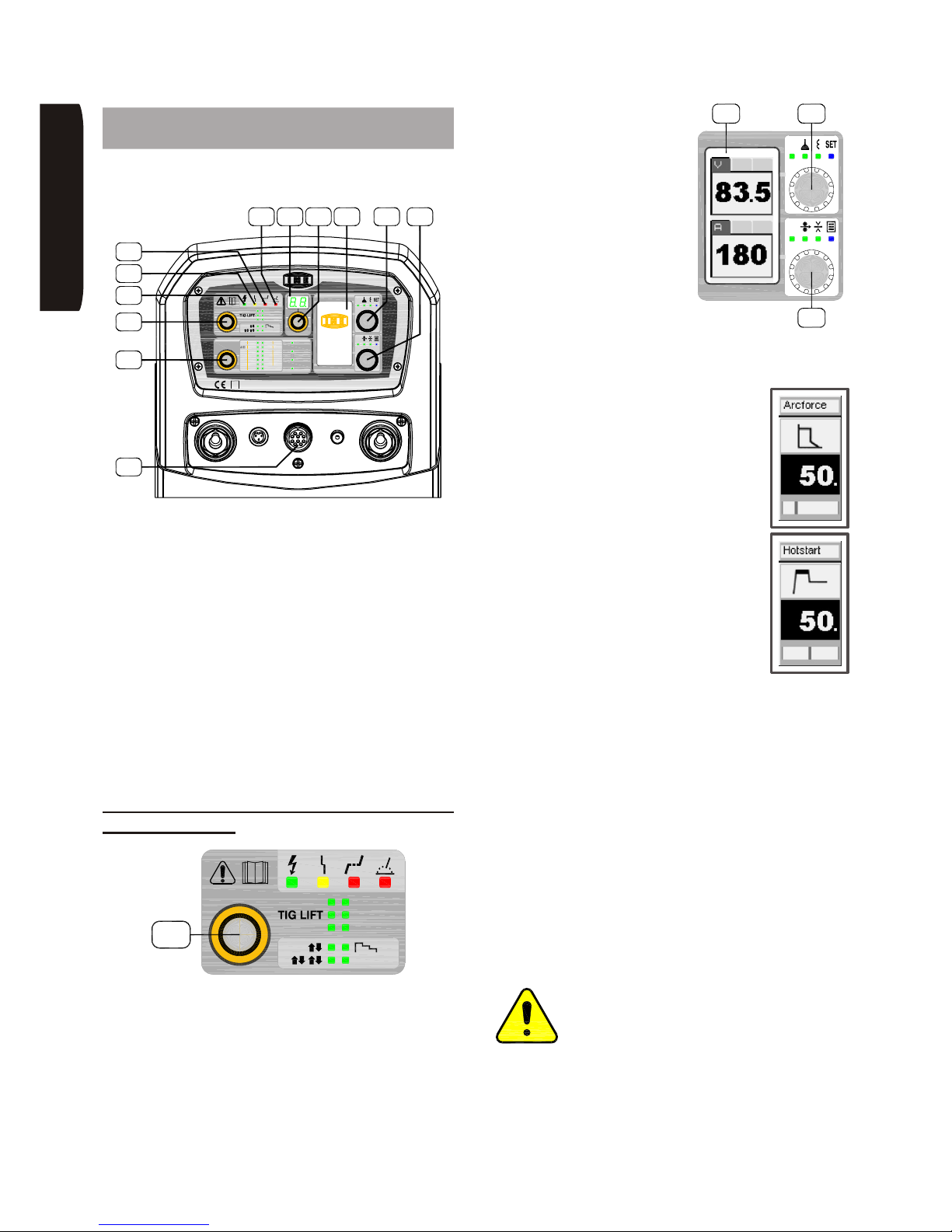
15 Impostazioni tramite interfaccia del
generatore
Con riferimento alla figura seguente sono di seguito
descritti i comandi e visualizzazioni.
L’accensione della macchina avviene ruotando in
posizione ON l’interruttore generale posto sul retro del
generatore. L’avvenuta accensione è segnalata dal led
verde ‘L1’.
Il led giallo ‘L2’ indica l’intervento dei dispositivi di
protezione e il display ‘D1’ indica il tipo di protezione
intervenuta (vedi paragrafo ‘Descrizione intervento
allarmi’).
Il led rosso ‘L3’ indica, in MIG/MAG, che con i parametri
impostati si effettua una saldatura in modalità
‘GLOBULAR’: modalità sconsigliata ai fini del risultato
di saldatura finale.
Il led rosso ‘L4’ indica la presenza di tensione in uscita.
In elettrodo è sempre accesa mentre in TIG e in
MIG/MAG segue l’andamento del ciclo di saldatura.
15.1 Impostazioni per la saldatura ad
elettrodo (MMA)
Il selettore ‘E1’ consente di selezionare il tipo di
saldatura che si vuole utilizzare.
• Premere il selettore ‘E1’ per qualche istante; il led
acceso comincia a lampeggiare.
• Ruotare la manopola in modo da far lampeggiare il
led corrispondente alla saldatura MMA (dopo 5
secondi di inattività la conferma è automatica).
Con il selettore ‘E5’ è
possibile impostare in ogni
momento la corrente di
saldatura che viene
visualizzata sul display ‘D1’.
Sul display ‘D1’ vengono
visualizzate anche la
tensione e la corrente
misurate durante la saldatura.
In MMA si possono impostare anche i seguenti
parametri:
• Hotstart: incremento percentuale della
corrente in partenza; facilita l’innesco
dell’arco elettrico.
• Arcforce: incremento percentuale
della corrente durante la saldatura al
verificarsi di cortocircuiti tra elettrodo e
pezzo; aiuta ad evitare lo spegnimento
dell’arco.
Per poter modificare questi parametri si deve agire in
questo modo:
• Premere il selettore ‘E4’ per due secondi; il led blu
‘SET’ si accende.
• Ruotare il selettore ‘E4’ per selezionare il parametro
da modificare.
• Ruotare il selettore ‘E5’ per modificarne il valore (una
barretta a scorrimento in basso sul display visualizza
il range di impostazione).
• Ruotare il selettore ‘E4’ per selezionare un altro
parametro.
• Al termine delle modifiche premere ‘E4’ per uscire
dalla modalità ‘SET’.
Attenzione: scegliendo la saldatura MMA è
importante, per evitare rischi e situazioni di
pericolo, controllare la posizione della torcia
MIG/MAG in quanto risulterà energizzata al
potenziale del positivo. (Evitare quindi il
contatto con il pezzo in lavorazione ed il circuito di
protezione di terra).
KMP 5000
S
TIGHF
MMA
MIG DP
USER
MIG
MIGP
JOB
OK
A
ESC
V
AlSi
Flux
Rutil
ø1.0ø1.0
Ar
2
Cored
CuSi SPECIAL
AL
CuAl
AlMg
Metal
Wire
CrNi
ArCO
Basic
ø1.6ø1.6
ø1.2ø1.2
2
2
CO2SG2/3
SG2/3
CrNi ArCO
NiCr ArHe
ø0.8ø0.8
kmp 5000
E5
L4 D1
E3
D2 E4
C5
L3
E2
L1
E1
L2
MMA
TIG HF
MIG P
MIG DP
MIG
USER
E1
OK
ESC
V
A
kmp 5000
D1 E4
E5
ONAILATI
Page 19
Page 17
INE S.p.A. Via Facca, 10 - 35013 Cittadella - PADOVA - ITALIA Tel. 049/9481111 - Fax 049/9400249 - [email protected] - www.ine.it
15.2 Impostazioni per la saldatura TIG
Il selettore ‘E1’ consente di selezionare il tipo di
saldatura che si vuole utilizzare.
• Premere il selettore ‘E1’ per qualche istante; il led
acceso comincia a lampeggiare.
• Ruotare la manopola in modo da far lampeggiare il
led corrispondente alla saldatura TIG LIFT o TIG HF
(dopo 5 secondi di inattività la conferma è
automatica).
Con il selettore ‘E5’ è
possibile impostare in ogni
momento la corrente di
saldatura che viene
visualizzata sul display ‘D1’.
Sul display ‘D1’ vengono
visualizzate anche la
tensione e la corrente
misurate durante la saldatura.
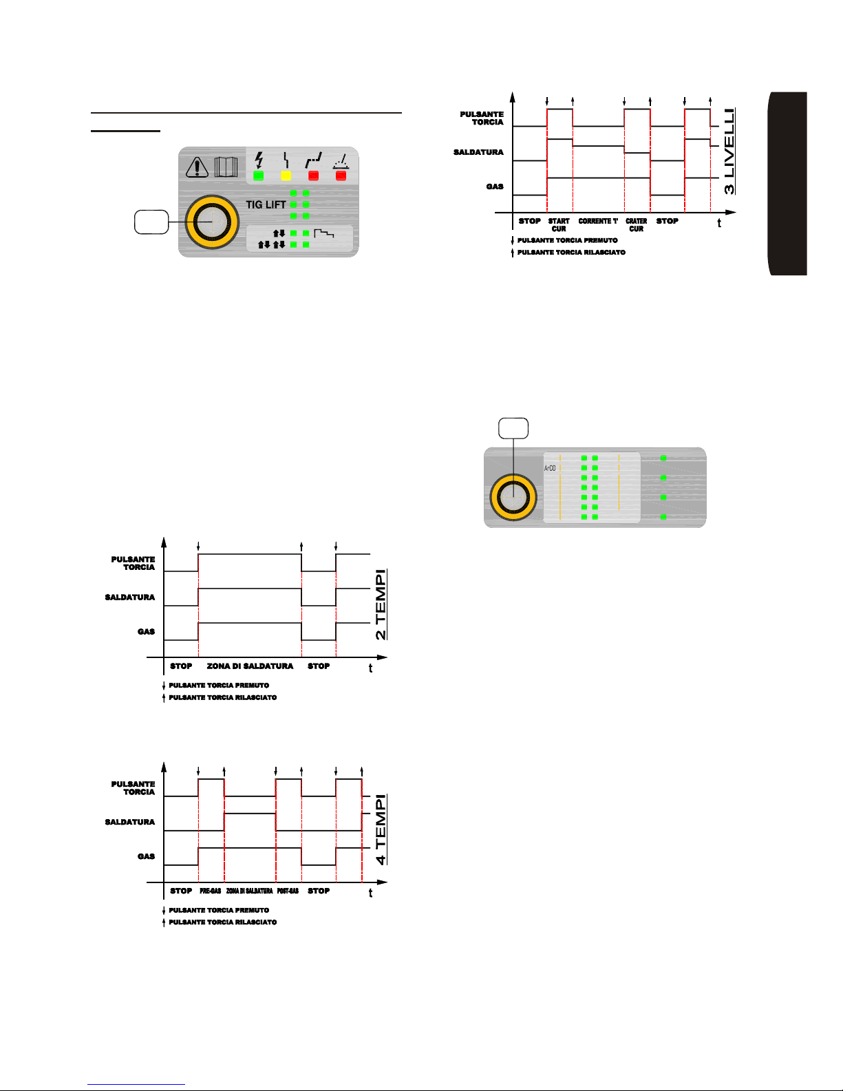
Per selezionare la modalità di funzionamento:
• Premere il selettore ‘E1’ per due volte; il led acceso
comincia a lampeggiare.
• Ruotare la manopola in modo da far lampeggiare il
led corrispondente alla modalità desiderata. Da
sinistra in alto: 2-tempi (ÇÈ), 4 tempi (ÇÈÇÈ),
3-livelli o USER (dopo 5 secondi di inattività la
conferma è automatica).
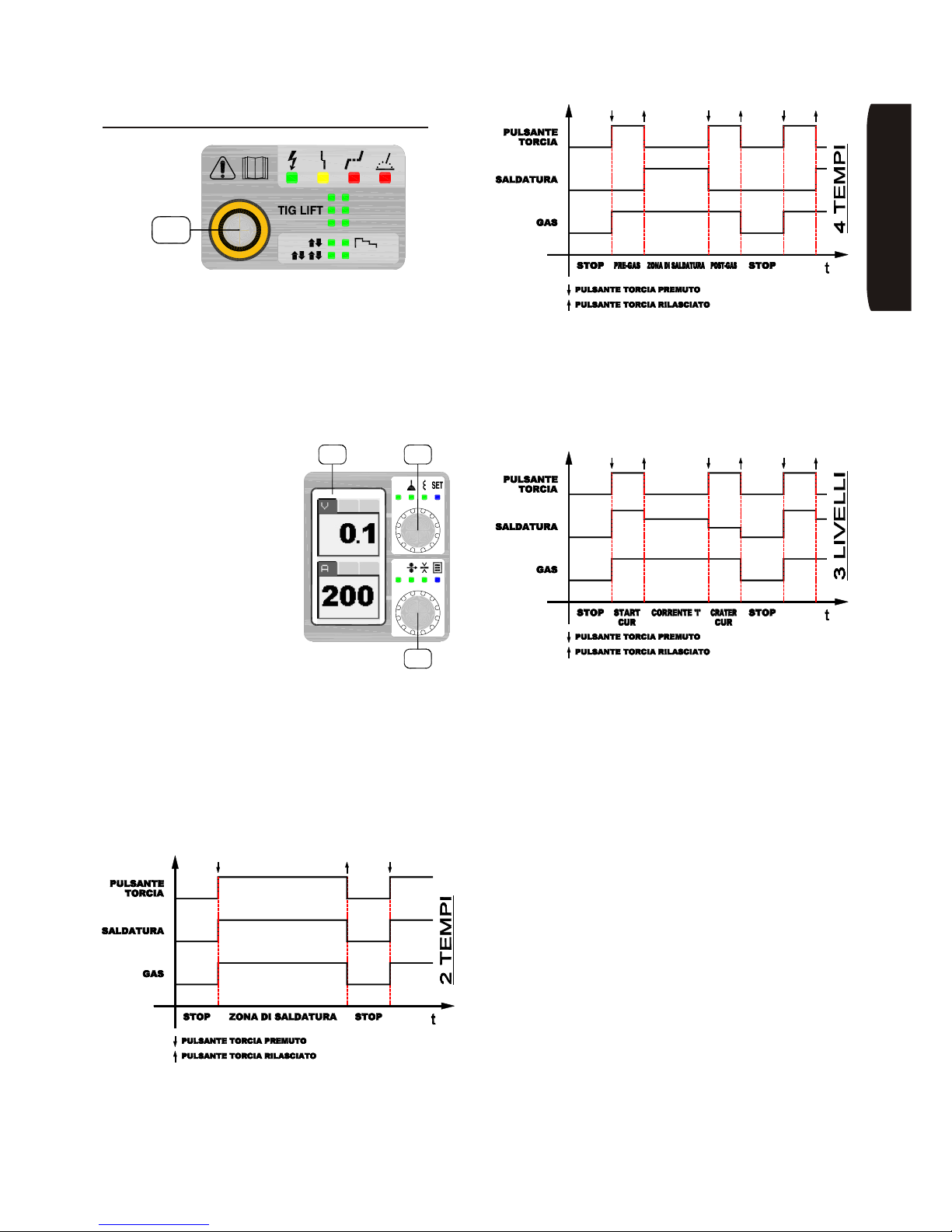
2-tempi: il processo di saldatura inizia nel momento in
cui si preme il pulsante torcia e si arresta al rilascio dello
stesso dopo aver effettuato la rampa di discesa ed
esaurito il tempo di post-gas.
4-tempi: premendo il pulsante torcia il processo di
saldatura inizia con un pre-gas manuale, al suo rilascio
inizia la saldatura vera e propria. Alla successiva
pressione del pulsante torcia la corrente di saldatura
effettua, se impostata, la rampa di discesa e si arresta
mentre il gas continua a fluire, al suo rilascio si ferma
anche il flusso del gas.
3-livelli ]: al premere del pulsante torcia il
processo di saldatura inizia dopo il pre-gas e la rampa
iniziale se impostati al valore di corrente impostato con
il parametro ‘Start cur’ (vedi spiegazioni successive).
Al rilascio del pulsante la corrente si porta al valore
impostato con ‘E5’. Alla successiva pressione del
pulsante torcia la corrente si porta al valore impostato
con il parametro ‘Crater cur’ (vedi spiegazioni
successive), al suo rilascio il processo si arresta ed
effettua la rampa di discesa ed il post-gas.
MMA
TIG HF
MIG P
MIG DP
MIG
USER
E1
OK
ESC
V
A
kmp 5000
D1 E4
E5
ONAILATI
Page 20
Page 18
INE S.p.A. Via Facca, 10 - 35013 Cittadella - PADOVA - ITALIA Tel. 049/9481111 - Fax 049/9400249 - [email protected] - www.ine.it
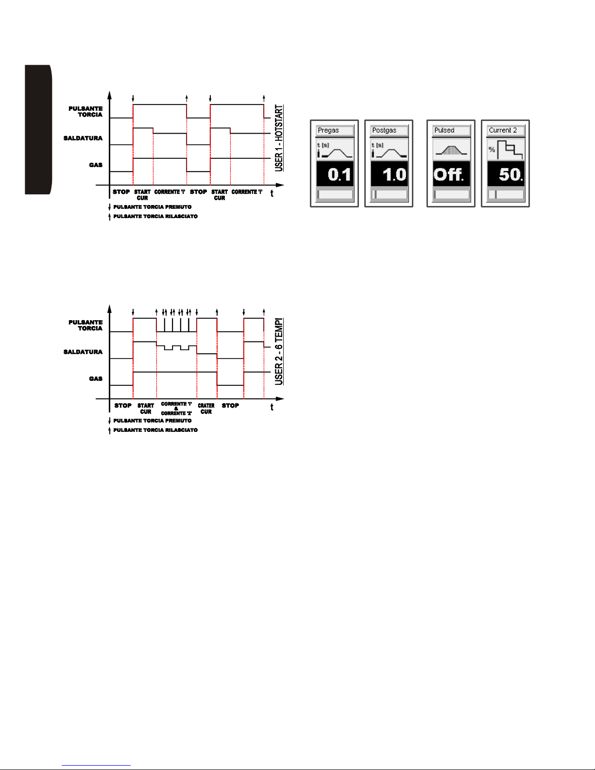
Selezionando USER sono disponibili ulteriori 2
modalità:
Hotstart: al premere del pulsante torcia il processo di
saldatura inizia, dopo il tempo di pre-gas, al valore di
corrente impostato con il parametro ‘Start cur’ e per un
tempo impostato con il parametro ‘T-Hotstart’ (vedi
spiegazioni successive), trascorso il quale la corrente
si porta al valore impostato con ‘E5’. Al rilascio del
pulsante torcia il processo si arresta.
6-Tempi: al premere del pulsante torcia il processo di
saldatura inizia al valore di corrente impostato con il
parametro ‘Start cur’ (vedi spiegazioni successive). Al
rilascio del pulsante la corrente si porta al valore
impostato con ‘E5’. Un breve impulso sul pulsante
torcia permette di passare alla corrente di saldatura
impostata con il parametro ‘Corrente 2’ (vedi
spiegazioni successive). Un ulteriore impulso fa
ritornare la corrente al valore impostato con ‘E5’, e così
via ciclicamente. Per concludere il processo si deve
premere il pulsante torcia: la corrente si porta al valore
impostato con il parametro ‘Crater cur’ (vedi
spiegazioni successive) ed al suo rilascio il processo si
arresta.
Per selezionare una tra le due modalità in USER:
• Premere il selettore ‘E5’ per qualche istante; il led blu
‘3’ si accende ed il display mostra il menù di
impostazione .
• Ruotare il selettore ‘E4’ per selezionare la pagina
‘Modo User’.
• Ruotare il selettore ‘E5’ per selezionare la modalità
scelta e confermare premendo ‘E5’.
• Ruotare il selettore ‘E5’ per selezionare ‘Esci’ e
confermare premendo ‘E5’.
All’interno dello stesso ‘SET’ si possono impostare
anche i seguenti parametri (le figure di seguito sono un
esempio delle schermate per l’impostazione dei
parametri):
• Pregas: tempo di pre gas (secondi).
• Postgas: tempo di post gas (secondi).
• Up slope: durata della rampa di salita della corrente
(secondi).
• Down Slope: durata della rampa di discesa della
corrente (secondi).
• Pulsed: attiva (On) o disattiva (Off) la pulsazione
della corrente.
• Base curr.: corrente di base per la pulsazione (in
Ampere).
• Frequency: frequenza (in herz) della pulsazione.
• Duty cycle: bilanciamento della durata della
corrente di saldatura rispetto alla corrente di base
(Es. al 50% significa che la durata della corrente di
saldatura è uguale alla durata corrente di base, al
30% che la durata della corrente di saldatura è
minore alla durata della corrente di base).
• Start cur: valore di corrente iniziale o primo livello
(solo per modo 3-livelli e USER_6-T).
• Crater cur: valore di corrente finale o terzo livello
(solo per modo 3-livelli e USER_6-T).
• Hotstart: valore di corrente iniziale in percentuale
sul valore di corrente impostato con ‘E5’ (solo per
modo USER_Hotstart).
• T-Hotstart: durata di Hotstart (solo per modo
USER_Hotstart).
• Current 2: percentuale del valore di corrente
impostato con ‘E5’ (solo per modo USER_6-T).
ONAILATI
Page 21
Page 19
INE S.p.A. Via Facca, 10 - 35013 Cittadella - PADOVA - ITALIA Tel. 049/9481111 - Fax 049/9400249 - [email protected] - www.ine.it
15.3 Impostazioni per la saldatura
MIG/MAG
Il selettore ‘E1’ consente di selezionare il tipo di
saldatura che si vuole utilizzare.
• Premere il selettore ‘E1’ per qualche istante; il led
acceso comincia a lampeggiare.
• Ruotare la manopola in modo da far lampeggiare il
led corrispondente alla saldatura MIG, MIG P
(pulsato) o MIG DP (doppio pulsato) (dopo 5
secondi di inattività la conferma è automatica)
Per selezionare la modalità di funzionamento:
• Premere il selettore ‘E1’ per due volte; il led acceso
comincia a lampeggiare.
• Ruotare la manopola in modo da far lampeggiare il
led relativo alla modalità desiderata. Da sinistra in
alto: 2-tempi (ÇÈ), 4 tempi (ÇÈÇÈ) o 3-livelli
(dopo 5 secondi di inattività la conferma è
automatica).
2-tempi: il processo di saldatura inizia nel momento in
cui si preme il pulsante torcia e si arresta al rilascio dello
stesso.
4-tempi: al premere del pulsante torcia il processo di
saldatura inizia con un pre-gas manuale, al suo rilascio
inizia la saldatura vera e propria. Alla successiva
pressione del pulsante torcia la saldatura si arresta
mentre il gas continua a fluire, al suo rilascio si ferma
anche il post-gas manuale.
3-livelli ]: al premere del pulsante torcia il
processo di saldatura inizia al valore di corrente
impostato con il parametro ‘Start cur’ (vedi spiegazioni
successive). Al rilascio del pulsante la corrente si porta
al valore impostato con ‘E5’. Alla successiva pressione
del pulsante torcia la corrente si porta al valore
impostato con il parametro ‘Crater cur’ (vedi
spiegazioni successive), al suo rilascio il processo si
arresta.
Con il selettore ‘E2’ si imposta il tipo di filo e il gas di
protezione utilizzato e successivamente il diametro
dello stesso. Con questa operazione viene selezionata
una curva di saldatura sinergica adatta al materiale
scelto (per uscire dai parametri preimpostati dalla
sinergia si rimanda ai paragrafi successivi).
• Premere il selettore ‘E2’ per qualche istante; il led
acceso comincia a lampeggiare.
• Ruotare la manopola in modo da far lampeggiare il
led corrispondente al tipo di filo e gas che si vuole
utilizzare (dopo 5 secondi di inattività la conferma è
automatica).
Per cambiare il diametro dei filo:
• Premere il selettore ‘E2’ per due volte; il led acceso
comincia a lampeggiare.
• ruotare la manopola in modo da far lampeggiare il
led corrispondente al diametro del filo utilizzato
(dopo 5 secondi di inattività la conferma è
automatica).
ONAILATI
MMA
TIG HF
MIG P
MIG DP
MIG
USER
E1
ø1.0ø1.0
ø1.6ø1.6
ø1.2ø1.2
ø0.8ø0.8
Ar
SPECIALCuSi
ArHe
ArCO
Flux
ArCO
Wire
Cored
AlSi Rutil
AL
CuAl
AlMg
Metal
CrNi
Basic
SG2/3
SG2/3
NiCr
CrNi
2
2
E2
CO
2
2
Page 22
Page 20
INE S.p.A. Via Facca, 10 - 35013 Cittadella - PADOVA - ITALIA Tel. 049/9481111 - Fax 049/9400249 - [email protected] - www.ine.it
Nei processi con sinergia, il selettore ‘E4’ permette di
impostare la correzione dell’altezza dell’arco e
dell’induttanza d’uscita. Per moficare questi valori:
• Premere ‘E4’ in sequenza per accendere il led
relativo al parametro da modificare e ruotare ‘E4’ per
cambiarne il valore.
Il parametro volt ‘V’ può essere impostato solamente in
MIG/MAG non sinergico (vedi funzionalità SET ->
Sinergia).
Il selettore ‘E5’ permette di impostare la corrente di
saldatura,la velocità del filo e lo spessore del pezzo.
Per moficare questi valori:
• Premere ‘E5’ in sequenza per accendere il led
relativo al parametro da modificare e ruotare ‘E7’ per
cambiarne il valore.
Tenendo premuto per più di due secondi il selettore ‘E4’
si entra nella modalità SET nel quale si possono
impostare i seguenti parametri avanzati:
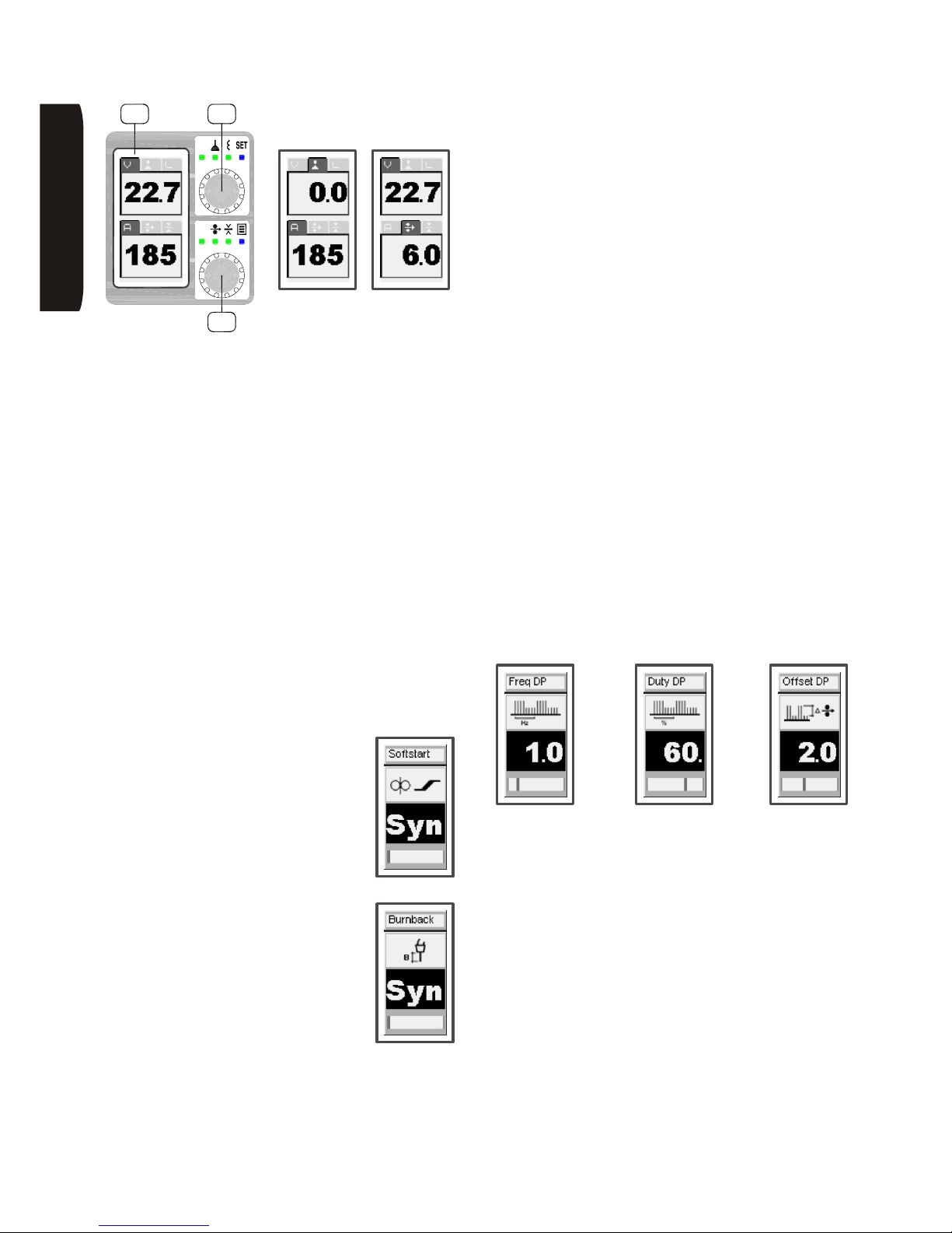
• Softstart: al premere del pulsante
torcia il filo avanza lentamente e si
porta alla velocità impostata solamente
allo scoccare dell’arco di saldatura. La
sua regolazione è automatica (’Syn’ sul
display) o regolabile da 1 a 100% della
velocità impostata del filo.
• Burnback: regola la lunghezza del filo
rispetto al terminale della torcia. La sua
regolazione è automatica (’Syn’ sul
display) o regolabile da 1 a 100%.
• Pregas: tempo di pre gas (secondi).
• Postgas: tempo di post gas (secondi).
• Sinergia: consente di attivare (ON) o disattivare
(OFF) la modalità sinergica. Il modo manuale
consente all’utente l’impostazione di tutti i parametri
in maniera del tutto analoga a quanto avviene in
generatori MIG/MAG tradizionali (con regolazione
della tensione, induttanza e velocità del filo). Questa
selezione non è presente in MIG P e MIG DP poichè
per una corretta saldatura ad arco pulsato è
necessario il controllo sinergico dei parametri.
Parametri impostabili solo in saldatura MIG DP (MIG
doppio pulsato):
• Freq DP: impostazione della frequenza di doppia
pulsazione da un minimo di 0,1Hz ad un massimo di
5Hz; questo parametro permette di controllare
l’alternanza tra i due punti di saldatura che
caratterizzano la doppia pulsazione.
• Duty DP: impostazione della simmetria
nell’alternanza tra i due punti di saldatura. Ad
esempio, un valore di duty cycle pari a 70 indica che
il punto di saldatura a velocità più elevata ha durata
pari al 70% del periodo di alternanza.
• Offset DP: i due punti di saldatura che
caratterizzano la doppia pulsazione derivano
dall’applicazione dell’offset, positivo e negativo, al
valore di velocità filo impostata. Ad esempio, con una
velocità filo impostata di 5 m/min ed un offset di 1
m/min, si alterneranno tratti si saldatura a 4 m/min
ed a 6 m/min alla frequenza impostata.
Per poter modificare questi parametri si deve agire in
questo modo (le figure precedenti sono un esempio
delle schermate per l’impostazione dei parametri):
• Ruotare il selettore ‘E4’ per selezionare il parametro
da modificare.
• Ruotare il selettore ‘E5’ per modificarne il valore (una
barretta a scorrimento in basso sul display visualizza
il range di impostazione).
• Ruotare il selettore ‘E4’ per selezionare un altro
parametro.
• Al termine delle modifiche premere ‘E4’ per uscire
dalla modalità ‘SET’.
Il cavo massa va collegato alla presa ‘A3’; la torcia va
collegata all’attacco ‘A5’. Gli eventuali tubi per il
raffreddamento della torcia agli attacchi ‘H2’.
ONAILATI
OK
ESC
V
A
kmp 5000
D1 E4
E5
Page 23
Page 21
INE S.p.A. Via Facca, 10 - 35013 Cittadella - PADOVA - ITALIA Tel. 049/9481111 - Fax 049/9400249 - [email protected] - www.ine.it
Note finali
Attraverso il connettore ‘C5’ posto sul frontale la
macchina può essere controllata tramite comandi a
distanza opzionali. La selezione del controllo remoto è
automatica all’inserimento del connettore e tale rimane
fino allo scollegamento fisico dello stesso.
L’inutilizzo della macchina attiva sul display ‘D1’ la
funzione di ‘screensaver’. Per riattivare la
visualizzazione normale basta agire con un qualsiasi
selettore sul frontale o con il pulsante torcia.
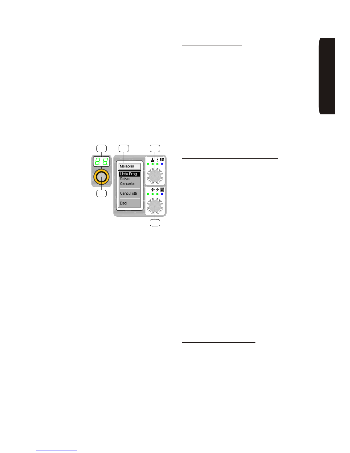
Memorizzazione programmi
In tutti i processi di
saldatura è possibile
memorizzare le
impostazioni
personali di saldatura
utilizzando il selettore
‘E5’. Sono
memorizzabili,
complessivamente,
100 programmmi.
Dopo aver impostato tutti i parametri desiderati,
accedere al menù ‘Memoria’.
Per accedere al menù di memorizzazione dal
generatore:
• Premere il selettore ‘E5’ per due secondi; il led blu ‘3’
si accende ed il display ‘D1’ mostra il menu di gestione
della memoria programmi.
Ruotando il selettore ‘E5’ si può selezionare la funzione
tra le seguenti disponibili:
Salvare un programma:
• Nel menù memoria selezionare ‘Salva’.
• Premere ‘E5’ e ruotare il selettore ‘E3’ per
selezionare la posizione di memoria desiderata
visualizzata sui display ‘D1’ e ‘D2’.
• Il lampeggiare del numero di locazione di memoria
su ‘D2’ indica che questa è libera; se il numero
selezionato è fisso indica che la memoria è già
utilizzata in tal caso, continuando l’operazione, si
sovrascriverà un programma esistente.
• Premere ‘E5’ per confermare oppure ‘E4’ per
annullare.
Per uscire dal menù ‘Memoria’ premere ulteriormente
‘E4’ oppure selezionare ‘Esci’ ruotando ‘E5’ e
confermare premendo ‘E5’.
Caricare e modificare un programma:
• Nel menù memoria selezionare ‘Lista Prog.’.
• Premere ‘E5’ e selezionare ruotando ‘E3’ la
posizione di memoria da caricare visualizzata sui
display ‘D1’ e ‘D2’ (il lampeggio del numero di
memoria su ‘D2’ indica che il ‘Programma non
esiste’).
• Premendo il selettore ‘E5’ il programma presente
nella posizione selezionata verrà caricato (esso sarà
modificabile e sovrascrivibile tramite la procedura di
‘salvare un programma’ vista al punto precedente).
Per uscire dal menù ‘Memoria’ premere ulteriormente
‘E4’ oppure selezionare ‘Esci’ ruotando ‘E5’ e
confermare premendo ‘E5’.
Cancellare un programma:
• Nel menù di memoria selezionare ‘Cancella’.
• Premere ‘E5’ e selezionare ruotando ‘E3’ la
posizione di memoria da cancellare visualizzata sui
display ‘D1’ e ‘D2’.
• Premendo ‘E5’ il programma presente in quella
determinata posizione di memoria verrà cancellato.
Per uscire dal menù ‘Memoria’ premere ulteriormente
‘E4’ oppure selezionare ‘Esci’ ruotando ‘E5’ e
confermare premendo ‘E5’.
Cancellare tutti i programmi:
• Nel menù di memoria selezionare ‘Cancella Tutti’.
• Premendo ‘E5’ tutti i programmi verranno cancellati,
per annullare l’operazione premere ‘E4’.
Per uscire dal menù ‘Memoria’ premere ulteriormente
‘E4’ oppure selezionare ‘Esci’ ruotando ‘E5’ e
confermare premendo ‘E5’.
ONAILATI
JOB
OK
ESC
V
A
kmp 5000
E3
D2 D1 E4
E5
Page 24
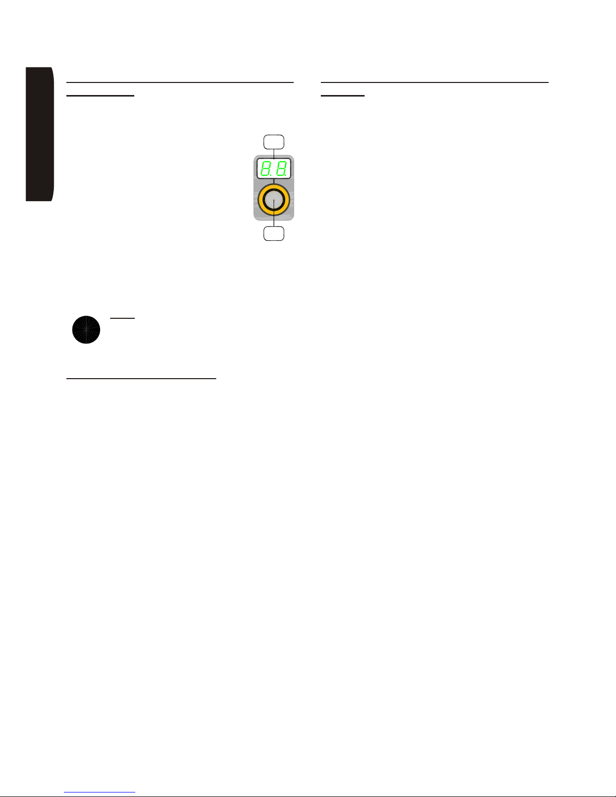
Page 22
INE S.p.A. Via Facca, 10 - 35013 Cittadella - PADOVA - ITALIA Tel. 049/9481111 - Fax 049/9400249 - [email protected] - www.ine.it
15.4 Selezione veloce dei programmi
(JOB MODE)
Per selezionare rapidamente un programma
memorizzato:
• Premere il selettore ‘E3’ per qualche
istante, il display ‘D2’ visualizza il numero
del primo programma memorizzato
disponibile.
• Ruotare il selettore ‘E3’ per scorrere i
programmi memorizzati; il programma
visualizzato è automaticamente
selezionato ed attivo immediatamente.
• La macchina risulta bloccata sul tipo di
saldatura e sui parametri impostati nel
programma memorizzato.
Per tornare alla normale modalità operativa si deve
premere il selettore ‘E3’ e sul display ‘D2’ devono
comparire 2 barrette orizzontali che indicano che non è
selezionato nessun programma.
Nota: la macchina all’accensione è
automaticamente impostata con i parametri
selezionati prima dell’ultimo spegnimento
della stessa.
15.5 Selezione della lingua
E’ possibile selezionare la lingua di interfaccia con
l’utente. Per accedere al menù di scelta della lingua:
• Premere il selettore ‘E5’ per due secondi; il led blu ‘3’
si accende.
• Ruotare il selettore ‘E4’ per selezionare il menù
‘Lingua’.
• Ruotare il selettore ‘E5’ per selezionare la lingua
desiderata.
• Confermare la scelta premendo il selettore ‘E5’; la
conferma è data dalla visualizzazione di un pallino
vicino alla lingua selezionata.
• Scorrere il menù fino alla voce ‘Esci’ ruotando ‘E5’,
premere ‘E5’ per uscire dal menù o premere ‘E4’.
15.6 Versione software e impostazioni
generali
E’ possibile visualizzare la versione software della
macchina, azzerare tutti i parametri alle impostazioni di
fabbrica, gestire il gruppo di raffreddamento e
visualizzare lo stato dei contatori base della macchina,
ad esempio il numero di ore di lavoro, il numero e la
data degli allarmi. Per accedere al menù ‘Imposta’:
• Premere il selettore ‘E5’ per qualche istante; il led blu
‘3’ si accende.
• Ruotare il selettore ‘E4’ per selezionare il menù
‘Imposta’.
• Ruotare il selettore ‘E5’ per selezionare la voce
desiderata.
• Per uscire dalla selezione premere ‘E5’, per
annullare premere ‘E4’.
• Scorrere il menù fino alla voce ‘Esci’ ruotando ‘E5’,
premere ‘E5’ per uscire dal menù.
ONAILATI
i
JOB
E3
D2
Page 25
Page 23
INE S.p.A. Via Facca, 10 - 35013 Cittadella - PADOVA - ITALIA Tel. 049/9481111 - Fax 049/9400249 - [email protected] - www.ine.it
16 Descrizione intervento allarmi
AL1 Sovracorrente sul motore trainafilo
AL2
Sovratemperatura sul modulo inverter
primario
AL3
Sovratemperatura sul modulo raddrizzatore
secondario
AL4 Sovratensione o sottotensione
AL5 Problema su unità gruppo di raffreddamento
AL7
Pulsante torcia premuto in fase di
accensione del generatore
AL8 Carrello trainafilo non compatibile
AL11
Segnalazione gruppo di raffreddamento
volutamente disabilitato
AL12
Segnalazione gruppo di raffreddamento
abilitato non presente
AL13 Guasto memoria scheda logica
17 Possibili anomalie dell’impianto di
saldatura
Vengono di seguito elencate le anomalie che più
frequentemente possono verificarsi nell’utilizzo dei
generatori SKYLINE KMP e l’indicazione delle possibili
cause.
A) Il generatore non salda correttamente. Verificare:
• che il selettore per la scelta del tipo di saldatura sia
posizionato correttamente
• che la polarità in MIG/MAG sia corretta rispetto al
tipo di filo che si utilizza
B) All’accensione della macchina il led verde ‘L1’ sul
frontale è acceso e la macchina non salda, verificare:
• verificare che il cavo della torcia, prese di potenza,
prolunga carrello/generatore e il cavo massa siano
integri
C) La macchina si blocca e il led giallo ‘L2’, durante
l’utilizzo, si accende con una frequenza superiore ai 4
minuti:
• verificare che il flusso d’aria per il raffreddamento dei
componenti non sia ostacolato dalla polvere o da
oggetti estranei posti nelle vicinanze delle prese
d’aria
• controllare il funzionamento del ventilatore
D) La macchina funziona solo in elettrodo (MMA) e non
in MIG/MAG, ossia il led rosso ‘L3’ sul frontale si
accende solamente nel primo caso:
• controllare la corretta chiusura del contatto elettrico
connesso al pulsante torcia
E) Saldatura irregolare:
• evitare di saldare in presenza di forti correnti d’aria
• controllare la continuità del flusso del gas verificando
il riduttore di pressione, l’elettrovalvola e i tubi di
collegamento
F) L’avanzamento del filo è irregolare, controllare:
• la bobinatura del filo
• che i rulli del trainafilo siano adeguati al tipo di filo, il
loro stato di usura e che la pressione del braccetto
premifilo sia adeguata
• che l’attacco torcia sia in asse con la cava del rullo
• la guaina della torcia ed, eventualmente, sostituirla
facendo attenzione che il diametro sia adeguato al
filo utilizzato e che la lunghezza sia esatta
• la frizione dell’aspo porta-bobina; se dovesse
funzionare a strappi va sostituito
G) Ad ogni interruzione della saldatura il filo si incolla al
tubetto di contatto:
• regolare il parametro ritardo potenza (BURN-BACK):
se il tempo è troppo lungo il filo si incolla al tubetto,
viceversa se è troppo breve il filo si incolla a bagno di
saldatura
ONAILATI
Page 26
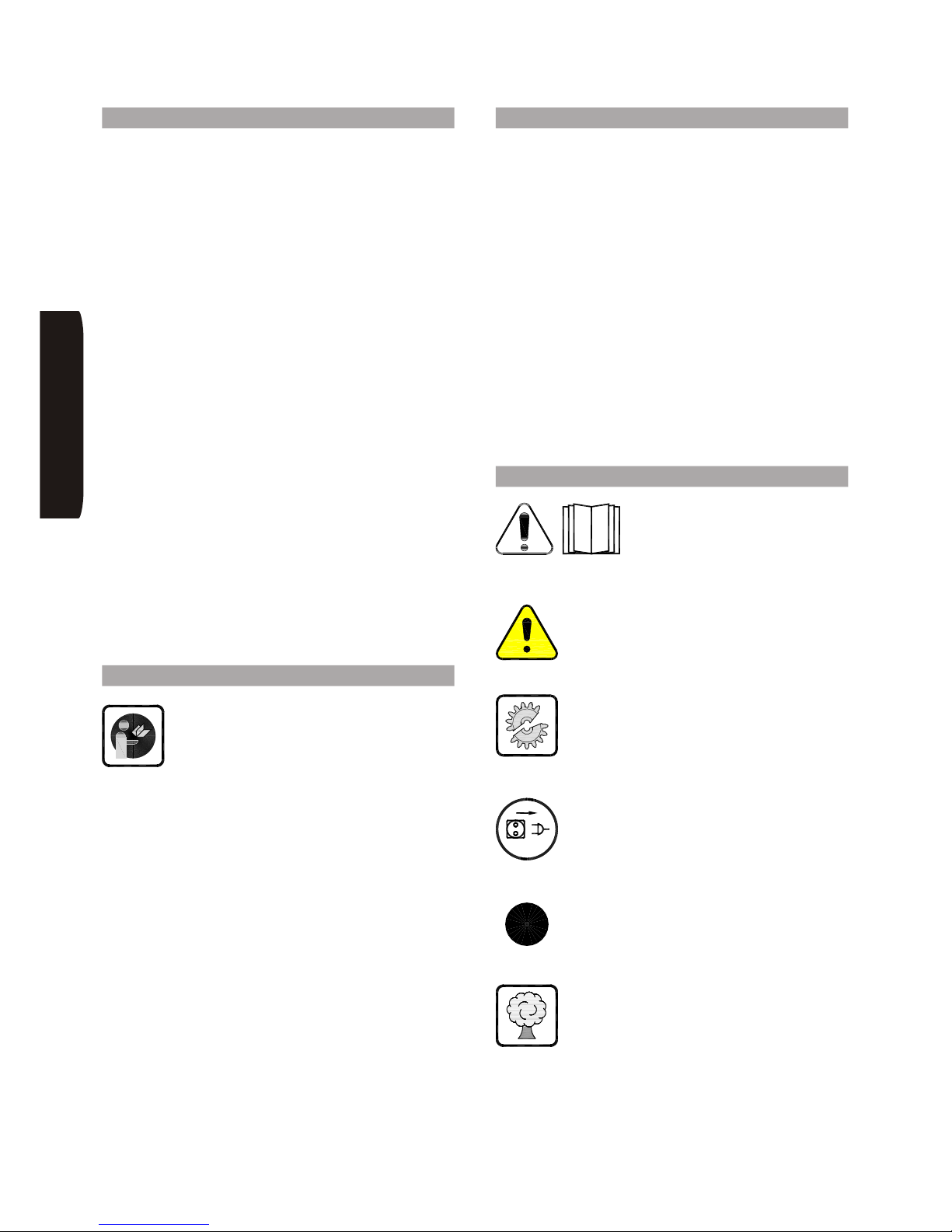
Page 24
INE S.p.A. Via Facca, 10 - 35013 Cittadella - PADOVA - ITALIA Tel. 049/9481111 - Fax 049/9400249 - [email protected] - www.ine.it
1 Introduction
SKYLINE KMP synergic inverter power source can be
used for MMA, TIG welding with Lift-Arc or HF start and
dc, pulsed or double-pulsed MIG/MAG welding with
solid or cored wire.
These power sources have been designed and
implemented on the base of the most updated and
innovative technologies conceived for inverters and
microprocessors in power electronics and signal
processing. Thus a system has been achieved that, in
addition to the traditional dependability of INE products,
is featuring high dynamics of the necessary control for
obtaining very good quality welding, together with a
more straightforward and easier use by the operator.
SKYLINE KMP welding machines are constructed
according to the following standards EN 60974:
• as far as operators health prevention against electric
shocks is concerned.
• as far as electromagnetic compatibility is concerned
(noise disturbing other electrical appliances
operating in the vicinity).
INE declines any liability should the welding machine
be used incorrectly (ex.: to defrost pipes, to charge
batteries, etc.) or modified by the customer or third
parties without any written approval by the
manufacturer.
INE generators have been designed for professional
use and must be used exclusively by adequately
trained persons.
2 General rules
It is possible to work without risks only after
having fully read and understood the
operating and safety instructions, and of
course by complying with these strictly.
The safety rules/laws of the country where
the equipment is installed are to be observed.
This system is designed for welding steel, aluminium
and its alloys, as well as copper.
It is protected electronically against overloads. Don’t
use fuses having a higher amperage than the one
specified in table “TECHNICAL DATA”.
Always close any doors of the machine before you start
welding.
3 Ambient conditions
The system can withstand the following ambient air
temperature ranges:
When welding:
-10°C to +40°C (+14°F to +104°F)
During transport and storage:
-25°C to +55°C (-13°F to +131°F)
Humidity is not to exceed:
50% at +40°C (104°F)
90% at +20°C (68°F)
Welding, transport and storage are to be done within
such ranges. Trespassing them is to be regarded as a
violation. The producer will not be responsible for
damages caused by this.
The environmental air must be free of conductive dust,
corrosive gases, acids and other substances that may
damage the system.
4 Meaning of the symbols
On the machine.
DANGER! Please read the
instructions contained in the
manual.
Death or serious injury hazard!
Failure to comply with the safety precautions
can cause accidents or severe
consequences and even death.
Damage hazard!
Failure to comply with the instructions and/or
the safety precautions can cause damages
to the system and to the pieces being
machined.
Detach the power supply plug!
Disconnect the power supply plug before
operating inside the system.
Informative notes and indications for a
proper and facilitated use of the product.
Environment protection information.
HSILGNE
i
Page 27
Page 25
INE S.p.A. Via Facca, 10 - 35013 Cittadella - PADOVA - ITALIA Tel. 049/9481111 - Fax 049/9400249 - [email protected] - www.ine.it
5 Prevention against electric shocks
The machine must be installed by
authorised persons with specific technical
and professional know-how, conforming to
the laws in force in the country where it is
installed.
Before connecting the power source to the mains,
always check that:
• the voltage received falls within ±10% allowance of
the nominal value displayed on the machine plate;
• the mains input is properly grounded (as provided in
the relevant legislation) and the yellow/green wire of
the welding machine is connected to the ground;
• the mains supply is equipped with a grounded
neutral conductor;
• the power source is in a dry and ventilated place.
When using the welding machine, make sure that the
following precautionary measures are taken in the
workplace:
• ensure that no metallic body may accidentally get
into contact with the power cables;
• do not carry out any welding operation in damp or
wet areas;
• ground any metallic parts falling within the operator’s
reach;
• keep all flammable materials away from the working·
area;
• ensure that the gas cylinder is secured so as not to
hit or be hit by or anyway come into contact with the
welding circuit;
• connect the work return lead of the welding circuit to
a place as close as possible to the welding area in
order to minimise the current path and the relevant
risks;
Make sure that welding torches
and cables are in perfect condition.
Furthermore, the operator should stick to the following
behavioural rules:
• do not connect welding machines in series or
parallel;
• in the case two or more welders should operate on
electrically connected parts, it is suggested that they
work at a suitable distance from each other and that
none of them touches two torches or electrode
holders at the same time;
• do not place the torch or electrode holder on metallic
surfaces: this might be a condition for the machine to
be started accidentally;
• always wear insulating garments.
6 Prevention against UV rays, fumes
and fires
Arc welding is a welding process by which
UV rays are emitted. Therefore the operators
must protect their eyes and face by wearing
the special masks provided with glasses
having an adequate protection degree.
Here below is a list of the recommended DIN
degrees or classes for the various procedures in
relation with the electric currents supplied.
MMA welding:
• grade 10 - up to 80 Amps
• grade 11 - from 80 to 180 Amps
• grade 12 - from 180 to 300 Amps
• grade 13 - from 300 to 480 Amps
• grade 14 - above 480 Amps
MIG/MAG welding:
• grade 10 - up to 80 Amps
• grade 11 - from 80 to 120 Amps
• grade 12 - from 120 to 180 Amps
• grade 13 - from 180 to 300 Amps
• grade 14 - from 300 to 450 Amps
• grade 15 - above 450 Amps
TIG welding:
• grade 10 - up to 40 Amps
• grade 11 - from 40 to 100 Amps
• grade 12 - from 100 to 180 Amps
• grade 13 - from 180 to 250 Amps
• grade 14 - from 250 to 400 Amps
• grade 15 - above 400 Amps
Operators should wear gauntlets, insulating shoes and
fireproof clothes to protect themselves from radiation,
slags and sparks.
Reflection and transmission of UV rays in workplaces
should be reduced by using antiflash welding screens
or panels.
In order to reduce the toxic action of welding
fumes, it is suggested to operate in
ventilated areas. Use fume extractors close
to the welding area, if ventilation is poor or
lacking.
If the piece to be welded is covered by chemicals
(solvents, paints, etc.), it should be carefully cleaned
prior to welding to prevent toxic gas emission.
It is strictly forbidden to weld on
fuel tanks, whether they are full or
empty.
Fire and/or explosion hazard!
HSILGNE
Page 28
Page 26
INE S.p.A. Via Facca, 10 - 35013 Cittadella - PADOVA - ITALIA Tel. 049/9481111 - Fax 049/9400249 - [email protected] - www.ine.it
7 Maintenance
Any repair work or replacement of spares
should be carried out by skilled personnel,
qualified to operate on electromechanical
systems.
Welders are allowed to remove the side
panels of the welding machine (after
disconnecting it from the mains) only to
remove any dust or dirt that may have been
taken in.
This operation must be executed with a jet of
compressed air (free of humidity and oil) at least every
three months, or more frequently in case of working in
quite dusty environments.
Check each day that there are no powder deposits and
broken pieces of wire on the wire feeder. If this is the
case, clean carefully so as to avoid any electric contact
with the wire feeder body.
8 Electromagnetic compatibility (EMC)
INE welding machines are conceived for use in
industrial applications only (CLASS A of CISPR11). If
they are used differently (e.g. for domestic use), they
may cause compatibility problems, as they may
interfere with other electrical appliances operating in
the vicinity (radios, phones, computers, etc.).
It’s the user’s responsibility to install the power source
and use it in the proper places so that no EMC problems
may arise. When judging the suitability of a workplace,
the presence of the following should be considered:
• telephone lines and sets
• receiving and transmitting radio/TV sets
• computers and control devices
• safety devices
• measuring instruments.
Special attention should be paid to people with
pace-makers and similar bio-electronic devices since
they may be influenced by electromagnetic fields.
These people are strongly suggested to keep away
from any places in which welding is going on.
In the event electromagnetic disturbance should occur,
it’s the user’s responsibility to solve the situation; INE,
as the manufacturer of the welding set in use, is ready
to assist.
For further information please refer to EN 60974-10
(Enclosure A, particularly) which regulates the matter in
the EEC.
This system complies with IEC standard 61000-3-12,
on condition that the maximum impedance (Zmax)
admitted to the system itself is lower than or equal, at
the point of interface between user system and public
system, to:
95 mW (KMP3200)
107 mW (KMP5000)
It is a responsibility of the installer or of the user of this
system to assure, in case by consulting the electric
energy distribution company, that the system itself is
connected to a power supply with correct impedance.
HSILGNE
Page 29
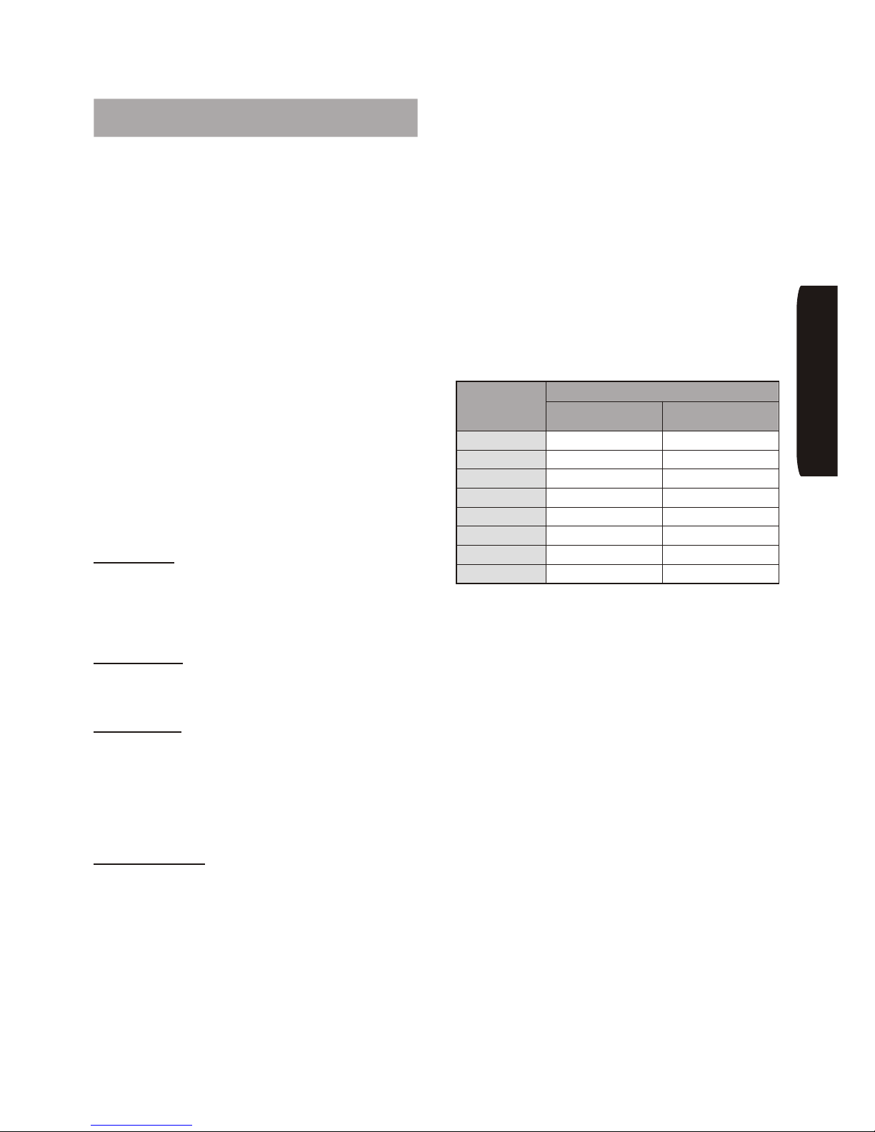
Page 27
INE S.p.A. Via Facca, 10 - 35013 Cittadella - PADOVA - ITALIA Tel. 049/9481111 - Fax 049/9400249 - [email protected] - www.ine.it
9 MMA welding procedure and
technical data
MMA welding procedure is the easiest among arc
welding procedures since it uses just a power source
connected to an electrode holder.
The electrode is made up by two fundamental parts:
• the CORE, which is made of the same material as
the weld piece (aluminium, steel, copper, stainless
steel) and has the function to add material to the
joint;
• the FLUX, made of different mineral and organic
substances mixed together, whose functions are:
A) gas protection
A part of the flux vaporises at the arc temperature
forming a column of ionised gas which protects the
molten pool;
B) addition of binding elements and slags
A part of the flux melts and some elements are added
to the weld pool; these join the material to be welded
and form the slag.
The welding procedure and the characteristics of the
weld deposit of each electrode depend on the type of
flux and on the material of the core.
The main types of electrode coating are:
Acid coating
This type of coating gives good weldability and may be
used either in ac or dc welding with the electrode holder
connected to the negative pole (straight polarity). The
weld pool is very fluid, therefore it can only be used in
flat position.
Rutile coating
This type of coating is the most commonly used
because it gives good weld appearance. It can be
welded in ac or dc with both polarities.
Basic coating
This type of coating is essentially used when high
mechanical properties are required. It is usually welded
in dc with the electrode holder connected to the positive
pole (reverse polarity), but there are also some types of
basic coating that can be used in ac welding. It is
suggested to keep basic coated electrodes in dry
places.
Cellulose coating
This type of coating is used in dc welding with the
electrode holder connected to the positive pole (reverse
polarity). It is essentially used for welding pipes due to
the viscosity of the weld pool and the deep penetration.
It requires a power source with adequate
characteristics.
MMA welding procedure requires the setting of the
following parameters:
A) Welding current
This parameter depends on the electrode type and
diameter and on the welding position. It is practically the
main variable, in that it determines penetration, weld
metal deposition and weld fillet thickness.
B) Arc voltage
It essentially depends on the distance between the
electrode tip and the workpiece. As the distance
increases, penetration decreases, weld fillet widens
and heavy spatters may appear.
As a guide, the table below shows the welding current
range to be used with the different electrode diameters
when welding carbon steel:
As a rough indication, the electrode to be used should
be as thick as the workpiece.
When the welding position is not horizontal, the weld
pool tends to flow down due to gravity. In these cases
this electrodes should be used in multiple passes. With
workpieces thicker than 3 mm, it is suggested to
adequately prepare the edges to be welded with a
single-Vee or double-Vee caulking. In this case welding
consists in filling the caulking besides joining the pieces
(a thin electrode should be used in the first pass so as to
avoid piercing the pieces).
The electric arc strikes when the electrode tip is
scratched on the workpiece and lifted quickly to the arc
starting distance. If this movement is too quick and the
distance excessive, the arc will blow out; on the
contrary, if the movement is too slow, it may
short-circuit the pieces. In the latter case, the electrode
may be detached from the workpiece by tearing it aside.
To improve the arc start, the power source may supply
an initial current peak; this technique is called ‘hot
start’. Once the arc strikes the electrode core begins to
melt dropping down onto the workpiece. The outer
coating, as it is consumed, provides the gas shielding
necessary to a good weld (as explained before).
Electrode
diameter
(mm)
Current (A)
min. max.
1,6 25 50
2 40 70
2,5 60 110
3,25 80 150
4 100 180
5 140 250
6 190 340
7 240 430
HSILGNE
Page 30
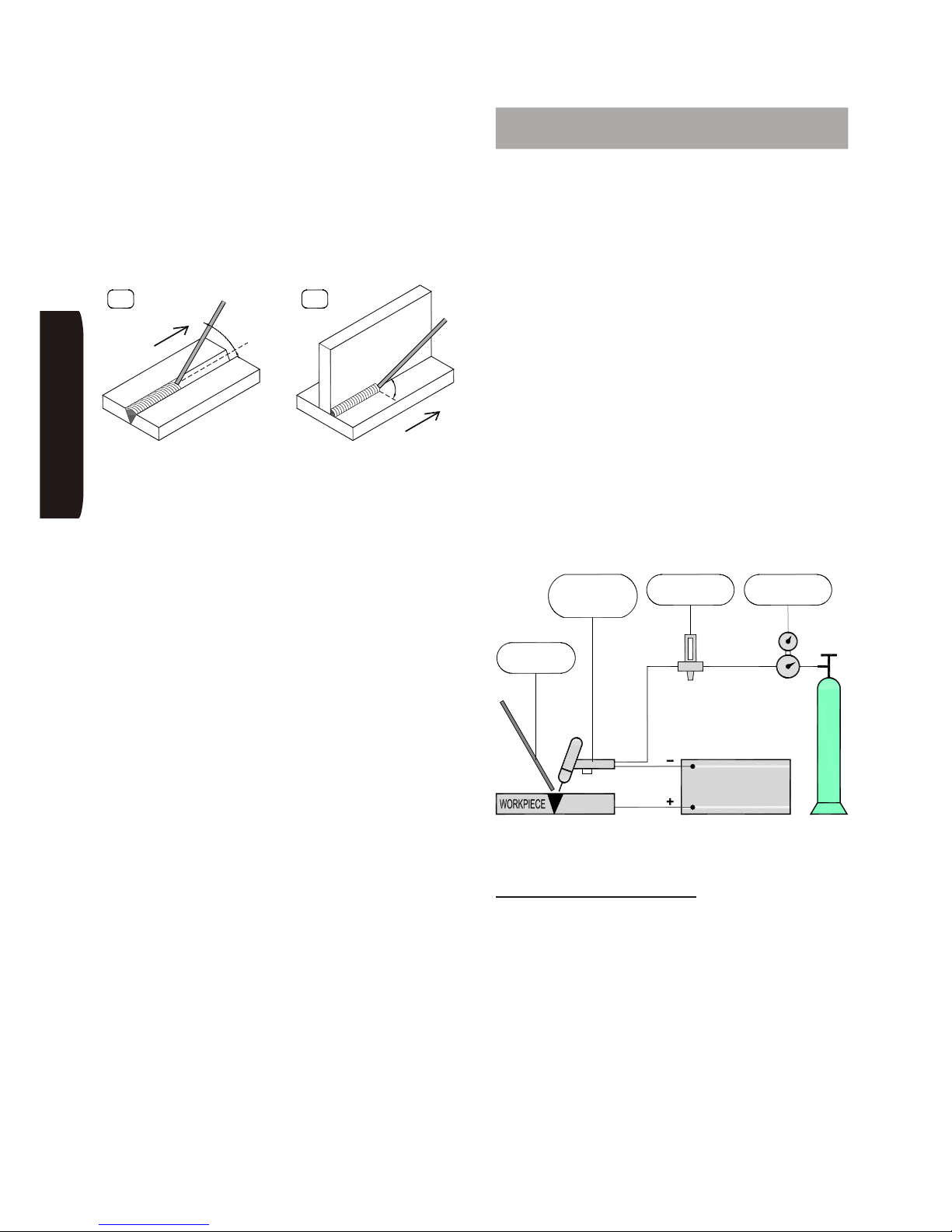
Page 28
INE S.p.A. Via Facca, 10 - 35013 Cittadella - PADOVA - ITALIA Tel. 049/9481111 - Fax 049/9400249 - [email protected] - www.ine.it
When welding, the operator might accidentally bring the
electrode too close to the weld pool, thus causing a
short circuit and consequently the blowing out of the
arc. In this case, the power source momentarily
increases the welding current supplied until the short
circuit ends; this technique is called ‘Arc Force’.
The techniques used to weld joints are several;
consequently, only a few indications on how to operate
can be given.
The figures above show two examples of a typical butt
(fig. A) and T weld (fig. B). The inclination of the
electrode varies according to the number of passes; its
movement is a traverse swinging with brief stops on the
bead sides in order to prevent weld material from
accumulating at the centre.
Welding with covered electrodes implies that the slag
shall be removed after each pass. This operation is
extremely important to achieve a uniform and smooth
weld. Slag is removed with a small hammer or with a
metal brush, if it is crumbly.
10 TIG welding: procedures and
technical data
TIG welding is carried out by means of an electric arc
sustained by a infusible electrode, of pure or alloy
tungsten. Unlike other welding procedures (MMA and
MIG) the electrode does not bring filler metal to the
weld. Filler metal is generally fed by the operator by
means of sticks made of the same material as the
workpiece. An inert gas shield (either Argon or Helium)
protects the arc. The electrode must not get in contact
with the workpiece, therefore the power source should
be equipped with an HF starter which causes the arc to
strike by means of a high voltage discharge (thus
avoiding any contact with the workpiece). But the arc
can also be started without HF. This type of arc start is
called “lift arc” and can only be used if the power source
is able to provide a very low initial short-circuit current
(few amps) which prevents the electrode from
consuming. This feature is a characteristic of inverters.
A TIG welding set is made up by:
- a dc or ac power source
- a torch with an infusible electrode
- an inert gas cylinder with a pressure reducer and flow
meter
TIG welding methods are several, and vary according
to the type of material and heat requested. The main
ones are illustrated below.
Direct current, direct polarity
By this procedure the torch is connected to the positive
socket of the power source and the work return lead to
the positive one. Most of the heat (about 70%) is
absorbed and given out by the workpiece, thus giving
deep penetration. This polarity is suited to all metals
except aluminium, magnesium and the relevant alloys,
but it does not offer any cleaning action.
HSILGNE
A B
45°
45
°
÷7
0
°
FLOW METER
FILLER
MATERIAL
INFUSIBLE
ELECTRODE
TORCH WITH
ARGO OR HELIUM
POWER SOURCE
REDUCER
PRESSURE
Page 31
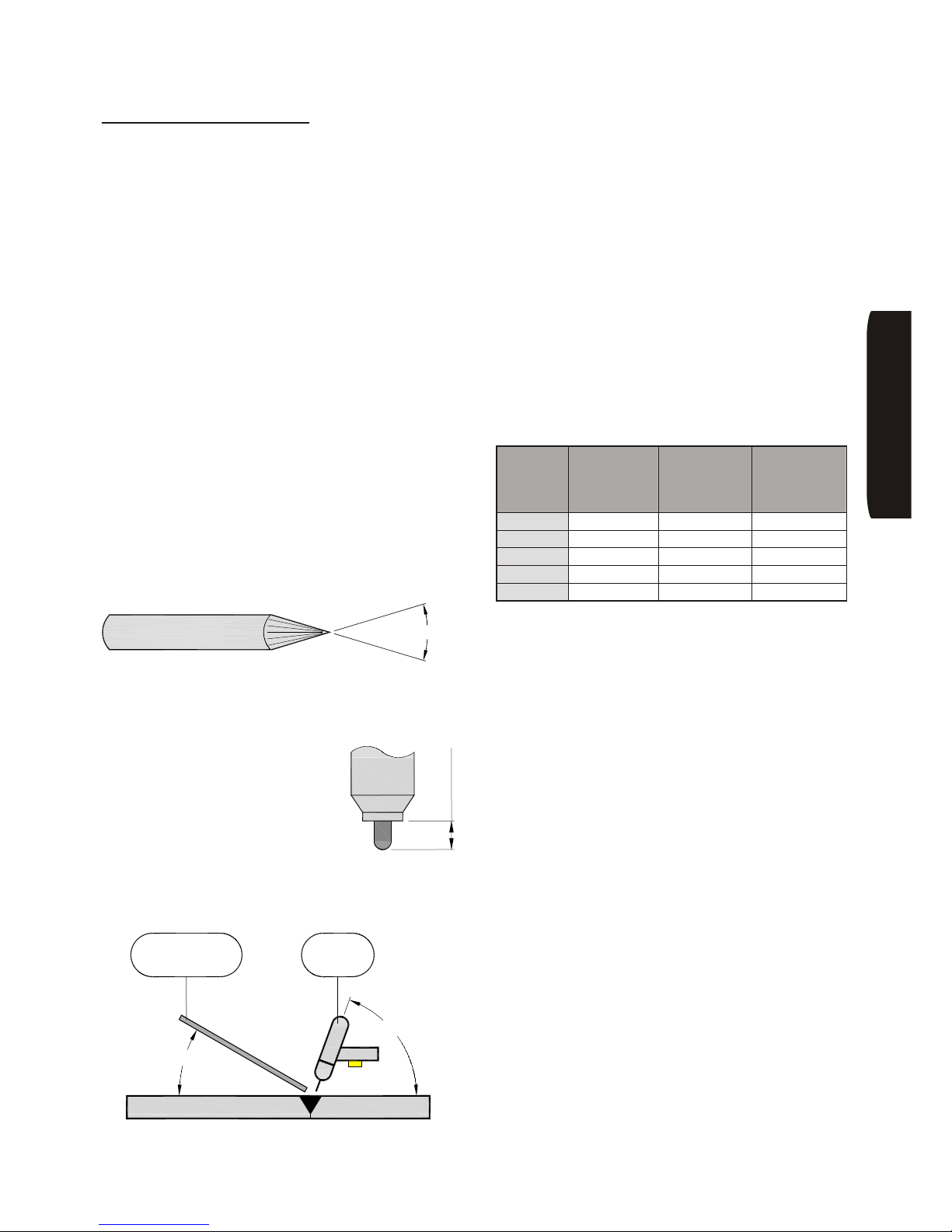
Page 29
INE S.p.A. Via Facca, 10 - 35013 Cittadella - PADOVA - ITALIA Tel. 049/9481111 - Fax 049/9400249 - [email protected] - www.ine.it
Pulsed current, direct polarity
The principle on which this procedure is based shares
the same features of the former one. The only thing to
be added is that the use of a pulsed current allows
better control of the weld pool in particularly difficult
conditions and especially when working with thin
materials.
The improvement introduced by this technique consists
in a reduced area of thermal alteration and fewer
deformations, cracks and gas bubbles inside the
melting area.
TIG welding is particularly suitable for those welds
which require high quality without even backwelding. It
is also used in those cases which require a good weld
bead without further processing (e.g. grinding). Since
TIG welding is more complex than other welding
procedures, the edges should be carefully cleaned and
prepared: a single-Vee caulking is suggested in case of
thickness above 3 mm.
When welding copper and aluminium, due to the
flowability of these metals, the use of a metal support
(e.g. a stainless steel support) is suggested when
backwelding.
Electrodes should be sharpened by means of a specific
grinder before being used in welding with currents on
direct polarity.
As shown in the figure above, the angle may be very
acute in the case of low currents (30° up to 30-40 A),
whereas it should be obtuse in the case of high currents
(over 90° for currents above 200A).
The electrode should be secured into
the torch so that its maximum
protrusion from the torch tip is 6÷9
mm, as shown in the figure (longer
protrusion only in the case of interior
angle welds).
The best results with this welding technique are
achieved by holding the torch and the filler metal stick
as shown in the following figure.
When either variable or reverse polarity is used, the
electrode tip should be round instead of sharp as in the
former case, due to the extreme heat developed on it. If
the electrode melts during the welding (its tip looks
drop-like), it should be replaced with a thicker one or, if
welding with variable polarity, the wave should be
adjusted so as to reduce the current positive
polarisation down to 20%.
As regards the material to be welded, the use of the
following electrodes is suggested:
• 2%- thorium tungsten (red-coloured) for steel, steel
alloys, nickel, copper and titanium
• pure tungsten (green-coloured) or tungsten with
zirconium (white-coloured) for aluminium and
magnesium
The table below shows the range of amperage used
according to the electrode diameter and the current
polarity used.
The filler metal sticks to be used are those commonly
sold for the purpose. These sticks are made of the
same base material as the workpiece and, in the case
of copper and aluminium, contain a small percentage
(lower than 10%) of de-oxidising agents such as silicon
or magnesium.
The shielding gas commonly used due to its low cost is
argon. Helium or argon/helium mixtures can be used
especially when welding thick materials in order to
improve penetration and increase welding speed.
Gas flow rates normally vary, as current increases, from
8 to 12 l/min in the case of argon and from 14 to 24 l/min
in the case of helium.
In order to prevent oxidation the post-gas flow should
be adjusted so that the weld and the electrode have
time to cool before being exposed to the atmosphere
oxygen. This time should be around a few seconds.
Electrode
diameter
(mm)
Direct current
Direct polarity
Direct current
Reverse
polarity
Alternate
current
Variable
polarity
1 10÷70 10÷15 10÷50
1.6 60÷150 10÷20 40÷100
2.4 100÷250 15÷30 80÷150
3.2 200÷400 25÷50 130÷230
4.8 350÷800 45÷80 200÷320
HSILGNE
30°÷120°
6÷9 mm
FILLER
WORKPIECE
MATERIAL
ß<30°
60°÷80°
TORCH
Page 32
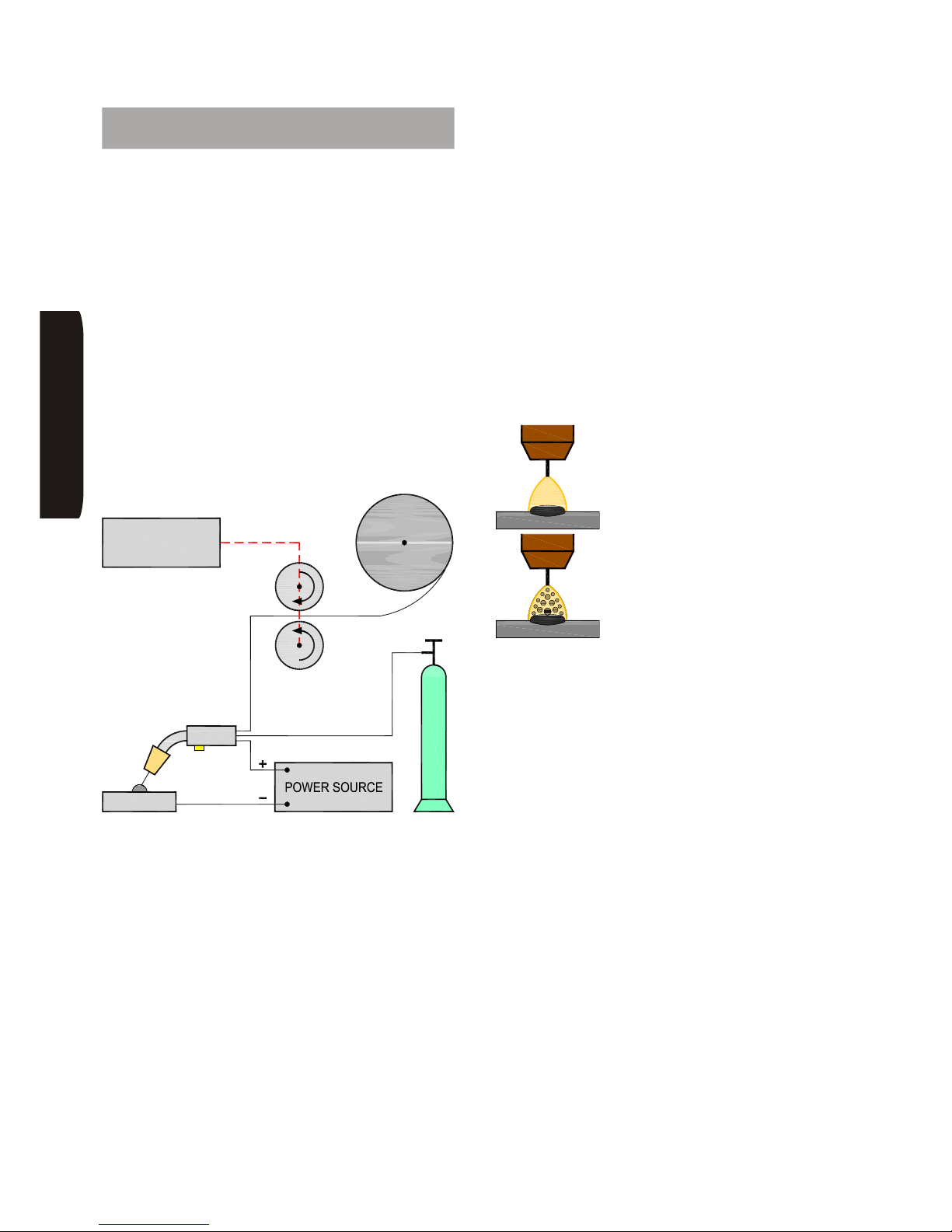
Page 30
INE S.p.A. Via Facca, 10 - 35013 Cittadella - PADOVA - ITALIA Tel. 049/9481111 - Fax 049/9400249 - [email protected] - www.ine.it
11 MIG/MAG welding: procedures and
technical data
MIG/MAG welding is a method used to weld carbon and
low-alloy steels in an inert environment (CO2 or
Argon/CO2) with the help of a solid or cored steel wire.
To weld stainless steel, the wire should match the
characteristics of the material being welded, and the
gas should be a mixture of Argon/CO2/O2.
To weld aluminium, the wire should be a type
compatible with the material and the gas should be pure
Argon; moreover, the use of a Teflon torch liner is
suggested.
A MIG/MAG welding machine is essentially made up
by:
• a dc power source (welding machine)
• a wire feeder
• a torch and a cable
• a gas cylinder with a flow meter and regulator
When welding, the torch is manoeuvred by the operator
along the joint while the wire is fed into the weld pool by
the wire feeder and forms the weld bead.
It is suggested that instruction should be sought as to
how the machine operates in the case of first use. As a
matter of fact, a basic knowledge of the welding
procedure is necessary to be able to adjust welding
parameters and to avoid spattering.
The adjustment of welding parameters consists in
finding out the correct balance between voltage and
wire speed to achieve a good-looking weld bead.
In order to avoid spattering, the correct torch position
from the workpiece should be maintained. In this
regard, special attention should be paid to a
phenomenon that generally takes places as an arc
deviation due to the electromagnetic forces at issue: the
magnetic blow. Such phenomenon mainly occurs when
welding angles or the inner corners of box-type pieces.
In order to reduce it, it is suggested to maintain the torch
in the opposite direction to the arc deviation, and to
choose an adequate point where the work return lead
should be connected.
Special attention is also to be paid to the welding of thin
materials or in the first pass of bevelled joints, as the
material might be pierced. In such cases welding with
low current values is suggested (short arc).
Two weld metal transfer methods are available in
MIG/MAG welding:
SHORT ARC
SPRAY ARC
SHORT ARC is used with arc voltage values lower than
24V and relatively low welding current values (lower
than 200 A/mm2). With this method the wire melts as it
is short-circuited by its own contact with the weld pool,
which causes the transfer of the molten drops. The arc
length is short, so the contact tip should protrude by 2-3
mm from the nozzle.
This method can be used in all positions (butt, fillet and
vertical welding) and generally in those cases such as
thin materials, first passes, etc., where low current
values are requested to prevent deformation and
piercing.
SPRAY ARC is on the contrary a welding method which
requires higher voltage and current values and in which
the weld metal when melting is sprayed into the weld
pool. The arc length is more evident and its intensity is
greater. The contact tip should be set back from the
nozzle (between 5 and 10 mm, as the welding current is
increased).
HSILGNE
WIRE SPOOL
PIECE
WIRE FEEDER
GAS
Page 33
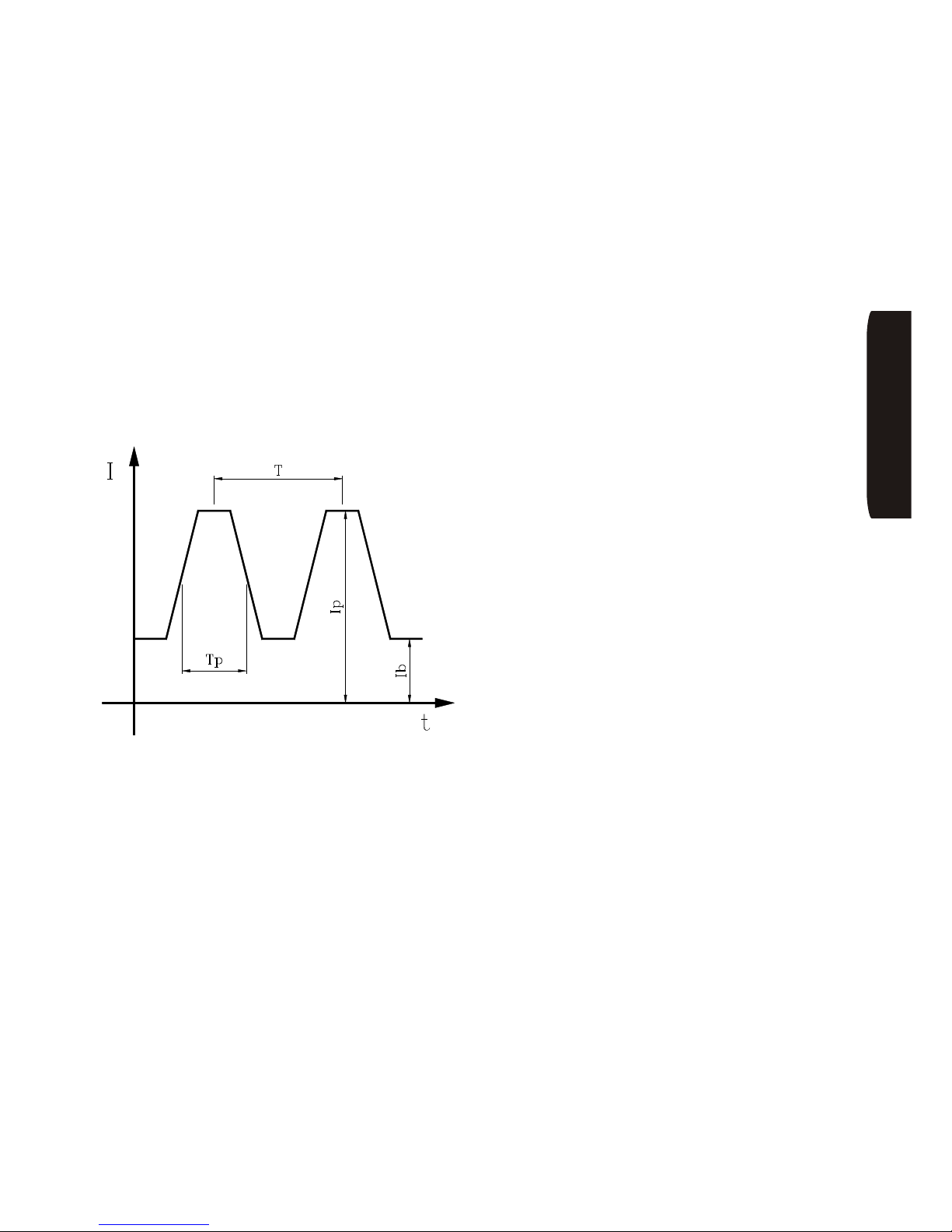
Page 31
INE S.p.A. Via Facca, 10 - 35013 Cittadella - PADOVA - ITALIA Tel. 049/9481111 - Fax 049/9400249 - [email protected] - www.ine.it
This method is only used in flat position of butt and fillet
welds on material of 4 mm and above, where a higher
deposition speed is required. The greater the arc length
(corresponding to a greater voltage V), with equal
current A, the wider and flatter the weld bead. This
means that by increasing the voltage the “deposition
cone” of the weld material widens.
At this point, special mention is deserved by the
pulsed-arc MIG/MAG welding procedure, which is
characterised by a non-constant, high-value pulse
current flow. Between pulses the current value is at a
minimum so as to keep the arc on without melting the
material. Thus the average welding current value can
be reduced even if welding with the spray-arc method.
So the advantages of this method (high-quality welds
thanks to the spraying of the molten metal, and the
variable weld bead width) can be achieved even at low
current values, typical of the welding of thin materials
and of welding positions other than butt welding.
To complete the topic, also the concept of synergy
(synchronisation) is to be mentioned. In a sync welding
machine, the couple welding voltage / welding current
is not set by the operator, who is only given the choice
of the arc power. This way time is saved since the
welding parameters are automatically adjusted and this
optimal functioning guarantees an almost spatter-free
welding.
HSILGNE
Page 34
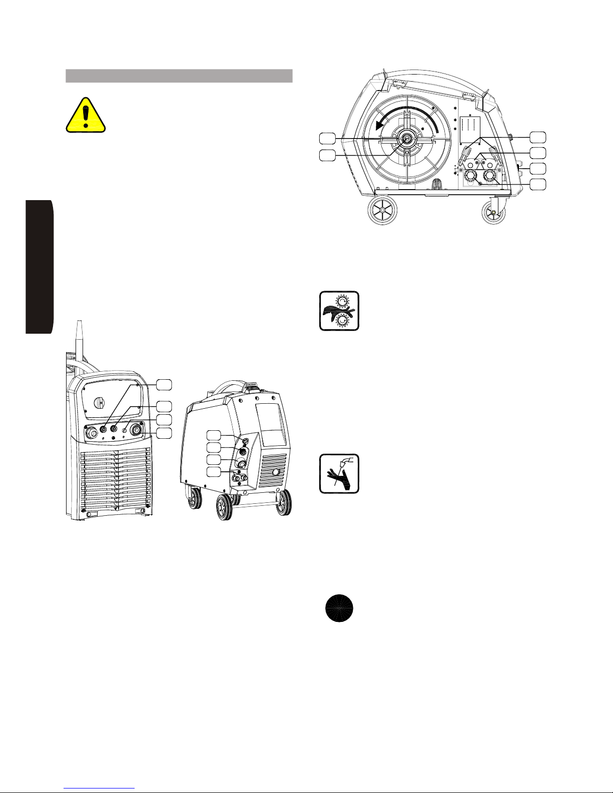
Page 32
INE S.p.A. Via Facca, 10 - 35013 Cittadella - PADOVA - ITALIA Tel. 049/9481111 - Fax 049/9400249 - [email protected] - www.ine.it
12 Set-up
The safety rules reported in the preceding
sections should be carefully followed when
setting up the machine, i.e. when connecting
the power source to its wire feeder by means
of the corresponding cable and when
connecting the mains input cable to the mains supply.
Connect the power cable to a socket with an adequate
current supply and insert the delayed line fuses with
an adequate rated value, as specified in the table of
TECHNICAL DATA (page 60).
Make sure that the yellow-green wire, which is the
earth wire, is properly connected to the ground (this will
protect the user).
To start up the machine follow these steps:
• Place the unit so that the vents are clear of any
obstruction to ventilation air. Keep it in a dry place
and at a distance of at least 0.5 m from walls, shields
or anything.
For the MIG/MAG welding:
• Connect the trolley with the power source tieing the
extension to the sockets ‘A1’ & ‘C1’ of the machine
and to the back sockets of the wire feeder ‘A4’, ‘C4’,
‘G3’ paying attention they are completely fixed.
• The gas pipe of the bundle of cables is to be
connected directly to the coupling of the pressure
reducer located on the gas cylinder.
• If the machine is provided with a cooling unit,
connect also the quick couplings for water ‘H1’,
referring to the colours.
• Fit the wire spool into the spool holder ‘Z1’ ensuring
that the direction of wire feed is correct. Release the
wire feed pressure arm ‘V2’. Insert the wire feed
roller ‘V3’ corresponding to the wire diameter being
used.
Pay special attention when fixing the rod
spool. DANGER! Do not touch the wire
feed motor cogwheels when they are
turning.
• Relocate the wire feed pressure arm and adjust
pressure ‘V1’. Feed wire by using inch button. Adjust
braking power by turning the spool holder ring nut
‘Z2’: it should be fastened as much as to avoid the
unwinding of the wire when a full spool is stopped.
• Feed wire into the torch liner and connect the torch to
its socket ‘A5’. Make sure the torch is secured by
tightening the connection with your own hands.
Then, while keeping the torch cable straight, feed
wire by using inch button (see paragraph 14).
During this operation never stay with your
body (and especially your eyes) in front of
the nozzle to see the wire coming out.
• Close the mobile panel on the wire feed motor.
• Connect the work return lead to the negative socket
‘A3’ and to a suitable, clean point of the workpiece.
• Attach the gas pipe to the pressure reducer. This one
must have been applied beforehand by following
scrupulously the instructions for its installation.
Technical note: when welding with cored
wire, gas is not used, since the core itself
protects the weld pool. To achieve the best
results, the welding polarity suggested by
the wire manufacturer should be used
(usually other than the one used with solid wire). To be
able to utilize the negative polarity on the wire, optional
kit PFCS0400015 is available.
HSILGNE
Z1
Z2
A5
V3
V1
V2
G1
A1
C2
C1
optional
C4
H1
A4
G3
i
Page 35
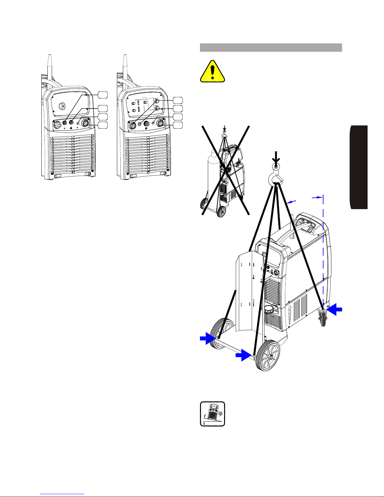
Page 33
INE S.p.A. Via Facca, 10 - 35013 Cittadella - PADOVA - ITALIA Tel. 049/9481111 - Fax 049/9400249 - [email protected] - www.ine.it
In case of TIG welding:
• Connect the gas hose between the gas cylinder
(equipped with flow meter and pressure reducer)
and the socket ‘G1’ on the power source rear panel;
connect the TIG torch to the socket ‘A3’ on the front
panel. Connect the torch gas hose and the torch
trigger wire to the corresponding ’G2’ and ‘C3’
connectors on the front panel.
• Connect the work return lead to the socket ‘A2’ on
the power source and clamp it to a clean area of the
workpiece.
In the case of MMA welding:
• Connect the electrode holder to its socket (positive
‘A2’ or negative ‘A3’), as requested by the type of
electrode.
• Connect the work return lead to the free socket on
the power source and clamp it to a clean area of the
workpiece.
13 Lifting: indications and precautions
To lift the machine use only the 4 holes on
the base of the generator trolley PR8: take
care to ensure that the lifting cables form a
small angle with respect to the vertical. All
the movable parts on the machine – e.g. gas
cylinder, generator-wire feeder extension, wire
feeder, torches, earth cables, etc. – must be removed
to avoid uncontrollable falls of all or part of the lifted
load.
The machine is to be positioned on a solid
and stable surface or floor which is adequate
to the machine’s weight. The maximum
inclination allowed is of 10°.
HSILGNE
MAX
15°
A3
G2
C3
A2
G1
A1
C2
C1
optional
Page 36
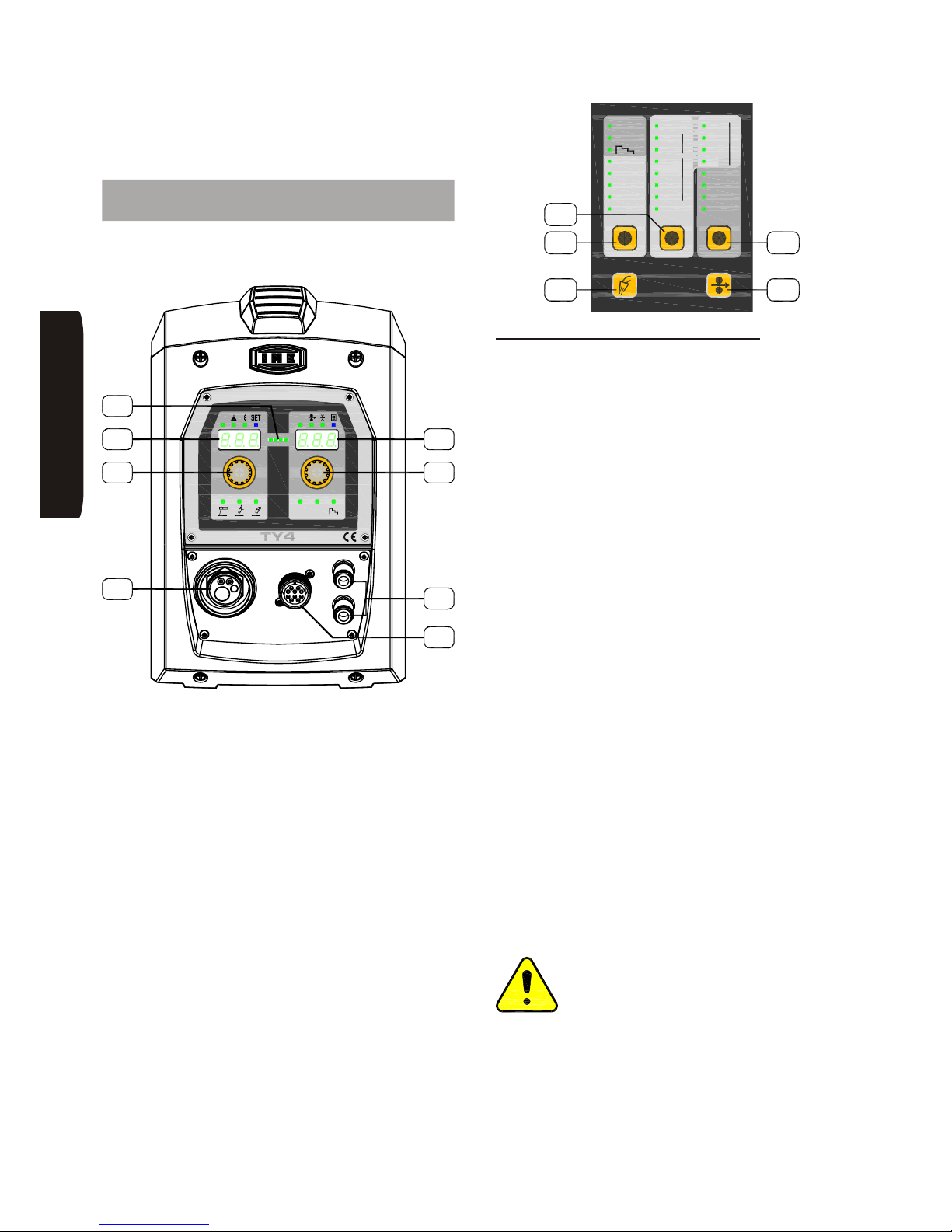
Page 34
INE S.p.A. Via Facca, 10 - 35013 Cittadella - PADOVA - ITALIA Tel. 049/9481111 - Fax 049/9400249 - [email protected] - www.ine.it
Functions and controls can be set both from the
machine and from the wire puller, in an independent
and interchangeable way.
14 Settings through TY4 wire feeder
interface
The controls of the machine are described here below
with reference to the following figure.
The machine is set to work by turning the main switch
placed on the rear panel to its ON position. The green
LED ‘L1’ will show when the machine is on.
The machine can be switched on by turning to its ON
position the main switch, located at the back of the
generator. When the machine is on, the ‘L5’ LED bar is
lit green.
The ‘L5’ LED bar has also the following functions:
• when lit yellow, it indicates that protection devices
have tripped (e.g. fuse blown), and displays ‘D3’ and
‘D4’ show which one has actually tripped (see
paragraph “Description of alarms”)
• when lit fuchsia, it indicates that a weld in
‘GLOBULAR’ mode is going to be made
• when lit red, it indicates the presence of output
voltage. In electrode, it is constantly lit; in TIG and in
MIG/MAG, it follows the course of the welding cycle
• when blinking blue, after welding is completed, it
indicates the HOLD function, which displays the
current and voltage values for 5 seconds before
returning to the setting interface
14.1 Settings for MMA welding
Press the ‘T1’ button and keep it pressed. Slide through
the LEDs until the MMA welding process indicator LED
gets lit. The release the button.
Caution: at generator outlet there will be no-load
voltage.
Via selector switch ‘E7’ it is possible to set the welding
current, which is shown on display ‘D4’. The output
voltage value is shown on display ‘D3’.
In the course of welding, display ‘D4’ will show the value
of actually delivered current.
Through the ‘SET’ menu, it is possible to set also the
following parameters:
• Hotstart HOT: percentage increase in initial current;
helps the electric arc starting.
• Arcforce ARC: percentage increase in welding
current in the case of short circuits; helps to prevent
the shutdown of the electric arc.
To be able to modify these parameters, there is to act as
follows:
• Press selector switch (knob) ‘E6’ for 2 seconds, and
the ‘SET’ blue LED will get lit.
• Rotate selector switch ‘E6’ for choosing the
parameter to be changed, shown on display ‘D3’.
• Rotate selector switch ‘E7’ for modifying its value,
shown on display ‘D3’.
• Rotate selector switch ‘E6’ for choosing another
parameter, or press this same selector switch for
quitting.
Attention: when choosing the MMA
welding, it is important, for avoiding risks and
dangerous situations, to check the position
of the MIG/MAG torch, as it will be energized
to the positive potential. (Thus you must
avoid contact with the piece being machined and with
the earth protection circuit).
HSILGNE
TY4TY4
AV
2T 4T
C6
E7
H2
D4
E6
A5
D3
L5
MIG
Argon
AlMg
ø 0.8
MIG P
MIG DP
SPECIAL
CuSi
CuAl
NiCr A rHe
ø 1.2
ø 1.0
ø 1.6
4T
MMA
2T
2
SG2/3
AlSi
CrNi
ArCO
2SG2/3 CO
Basic
CrNi
Metal
Rutil
FCAW - ArCO
2
PRG
KMP
T1
T4
T2
T3
T5
321
Page 37
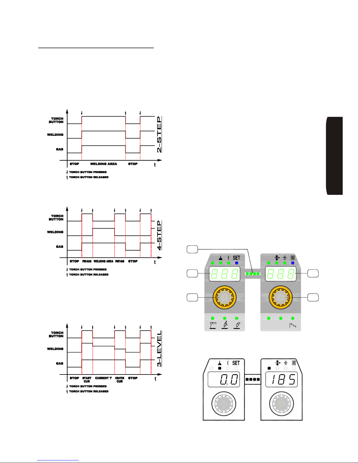
Page 35
INE S.p.A. Via Facca, 10 - 35013 Cittadella - PADOVA - ITALIA Tel. 049/9481111 - Fax 049/9400249 - [email protected] - www.ine.it
14.2 Settings for MIG /MAG welding
Press the ‘T1’ button and keep it pressed. Slide through
the LEDs until the LED associated to welding process
to be used gets lit. Any one of the following processes
can be selected: MIG, MIGP (pulsed) or MIG DP
(double pulsed). Then release the button.
A fast pressure of button ‘T1’ allows cycling among 2T,
4T and three levels; on the contrary, a longer pressure
than two seconds allows changing the welding process.
2-step mode: the welding process begins as soon as
the torch trigger is pressed and stops as soon as it is
released.
4-step mode: when the torch trigger is pressed, the
welding process begins with a manual pre-gas; when
released, the real welding begins. When the torch
trigger is pressed again, the welding will stop, although
gas will still flow; when released, also the manual
post-gas will stop.
3-level mode ]: when the torch trigger is pressed,
the welding process begins at the current value set with
parameter IN1 (see explanation below). When the
torch trigger is released, the current will rise up to the
value set with ‘E7’. When the torch trigger is pressed
again, the current will drop down to the value set with
parameter CRA (see explanation below). When the
torch trigger is released again, the welding process will
stop.
With button ‘T2’ you can set the type of wire and the
protection gas utilized. This operation allows selecting
a synergic welding curve suitable for the chosen
material (for exiting from the preset parameters of
synergy, please refer to the next paragraphs).
Button ‘T3’ allows selecting the diameter of the wire to
be used.
Button ‘T4’ (gas test) is used for checking the presence
of the welding gas, for verifying the correct flow and for
taking the air out of the circuit.
Button ‘T5’ is used for feeding the wire manually. It is
utilized in particular during a roll change.
By pressing button ‘T5’, the motor will commence
feeding and, with an acceleration ramp of a few
seconds, it will lead the wire at a speed of 15 m/min.
During the whole operation, LED bar ‘L5’ will display the
dragging effort.
With a double and fast pressure of button ‘T5’, feed
direction is reversed so that the wire is recovered. This
is accomplished at minimum speed.
In the processes with synergy, selector switch ‘E6’
permits setting the arc height correction and the output
inductance. For changing these values:
HSILGNE
V A
2T 4T
E6 E7
L5
D3
D4
V A
Page 38
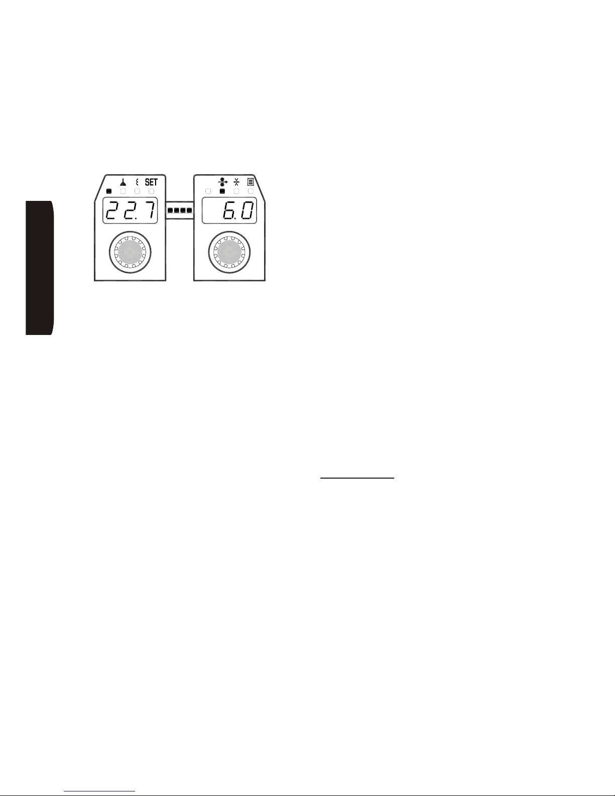
Page 36
INE S.p.A. Via Facca, 10 - 35013 Cittadella - PADOVA - ITALIA Tel. 049/9481111 - Fax 049/9400249 - [email protected] - www.ine.it
• Press selector switch ‘E6’ in sequence for lighting
the LED related to the parameter to be changed, and
rotate ‘E6’ itself for changing the value.
The voltage parameter ‘V’ can be setting only in no
synergic MIG/MAG (see operation SET -> SYN).
Via selector switch ‘E7’ it is possible to set the welding
current, the wire speed and the piece thickness. For
modifying these values:
• Press selector switch ‘E7’ in sequence for lighting
the LED related to the parameter to be changed, and
rotate ‘E7’ itself for changing the value.
By keeping selector switch ‘E6’ pressed for more than
two seconds, you will go into the SET mode, where you
can set the following advanced parameters:
• Softstart SOF: when the torch trigger is pressed the
wire is fed slowly, reaching the set speed only when
the welding arc strikes. It is automatically adjusted
(SYN on the display) or adjustable from 1 to 100% of
the speed set for the wire.
• Burnback BUR: it adjusts power delay with the aim
of optimising the end of the welding process (that is,
the length of the wire with respect to the end of the
torch). It is automatically adjusted (SYN on the
display) or adjustable from 1 to 100%.
• Pre-gas PRE: pre-gas time (seconds)
• Post-gas POS: post-gas time (seconds
• Synergy SYN: to turn the synergy mode ON (1) or
OFF (0). In the manual mode it lets the user set all
the parameters exactly as they would be for
traditional MIG/MAG generators (adjustment of wire
tension, inductance and speed). This selection is not
available in MIG P or MIG DP because the
parameters need to be synergically controlled for a
correct pulsed arc welding.
Other parameters that can only be set in MIG DP
welding (double-pulsed MIG):
• Freq DP DPF: double-pulse frequency from a
minimum of 0.1 Hz to a maximum of 5 Hz; this setting
changes the high/low pulses per cycle in Hz. The
higher the frequency the finer the ripple shape, the
more penetration is gained along with a higher speed
of pulses and travel speed
• Duty DP DPD: this setting changes the % of the
time the high pulse is used, so resulting in a hotter
weld with a broader weld width
• Offset DP DPO: sets the difference between the
peak current on the high and low pulse. The higher
the number increases the spacing between each
ripple shape. This setting is used in conjunction with
the Freq DP to obtain TIG like weld deposits
To change these parameters proceed as follows (the
figures shown above are an example of the screen
pages for setting the parameters):
• Turn selector ‘E6’ to select the parameter to change.
• Turn selector ‘E7’ to change its value.
• Turn selector ‘E6’ to select another parameter or
press ‘E6’ to exit the ‘SET’ mode.
Concluding notes
By means of the connector ‘C6’ on the front panel, the
machine may be controlled using optional remote
controls. The selection of the remote control is
automatic when the connector is inserted and remains
in this way until it is physically disconnected.
Storing programs and general settings
It is possible to store tailored welding recipes by using
the ‘E7’ selector switch. In total, 100 programmes can
be stored.
After set all the desired parameters, access the storage
menu by pressing the selector ‘E7’ for two seconds.
Save a program:
• Rotate knob ‘E6’ and select STO (Store).
• Rotate knob ‘E7’ for choosing the desired memory
location, shown on display ‘D4’.
• If such chosen memory number is blinking, it means
it is free. On the contrary, if it is steady lit, it means
that it is already occupied: by confirming the
operation, the existing programme will be
overwritten.
• Press ‘E7’ for two seconds to confirm or ‘E6’ to
cancel. The LED lights up blue ‘3’ for 2 seconds
indicates the save operation is complete.
HSILGNE
V A
Page 39

Page 37
INE S.p.A. Via Facca, 10 - 35013 Cittadella - PADOVA - ITALIA Tel. 049/9481111 - Fax 049/9400249 - [email protected] - www.ine.it
Load and modify a program:
• Rotate knob ‘E6’ and select LOD (Load).
• Rotate knob ‘E7’ for choosing the memory location to
be loaded (if the number of the chosen position is
blinking, it means that the ‘Programme doesn’t
exist’).
• Press ‘E7’ for two seconds to confirm or ‘E6’ to
cancel. The LED lights up blue ‘3’ for 2 seconds
indicates the load operation is complete.
Delete a program:
• Rotate knob ‘E6’ and select DEL (Delete).
• Rotate knob ‘E7’ for choosing the memory location to
be deleted (if the number of the chosen position is
blinking, it means that the ‘Programme doesn’t
exist’).
• Press ‘E7’ for two seconds to confirm or ‘E6’ to
cancel. The LED lights up blue ‘3’ for 2 seconds
indicates the delete operation is complete.
Cooling unit setting:
• Rotate knob ‘E6’ and select H2O.
• Rotate knob ‘E7’ for choosing ON to enable or OFF
to disable the cooling unit.
• Press ‘E6’ to exit from menu.
Reset to factory setting
• Rotate knob ‘E6’ and select FAC.
• Rotate knob ‘E7’ for choosing YES.
• Press ‘E7’ for two seconds to confirm or ‘E6’ to
cancel. The LED lights up blue ‘3’ for 2 seconds
indicates the reset operation is complete.
HSILGNE
Page 40
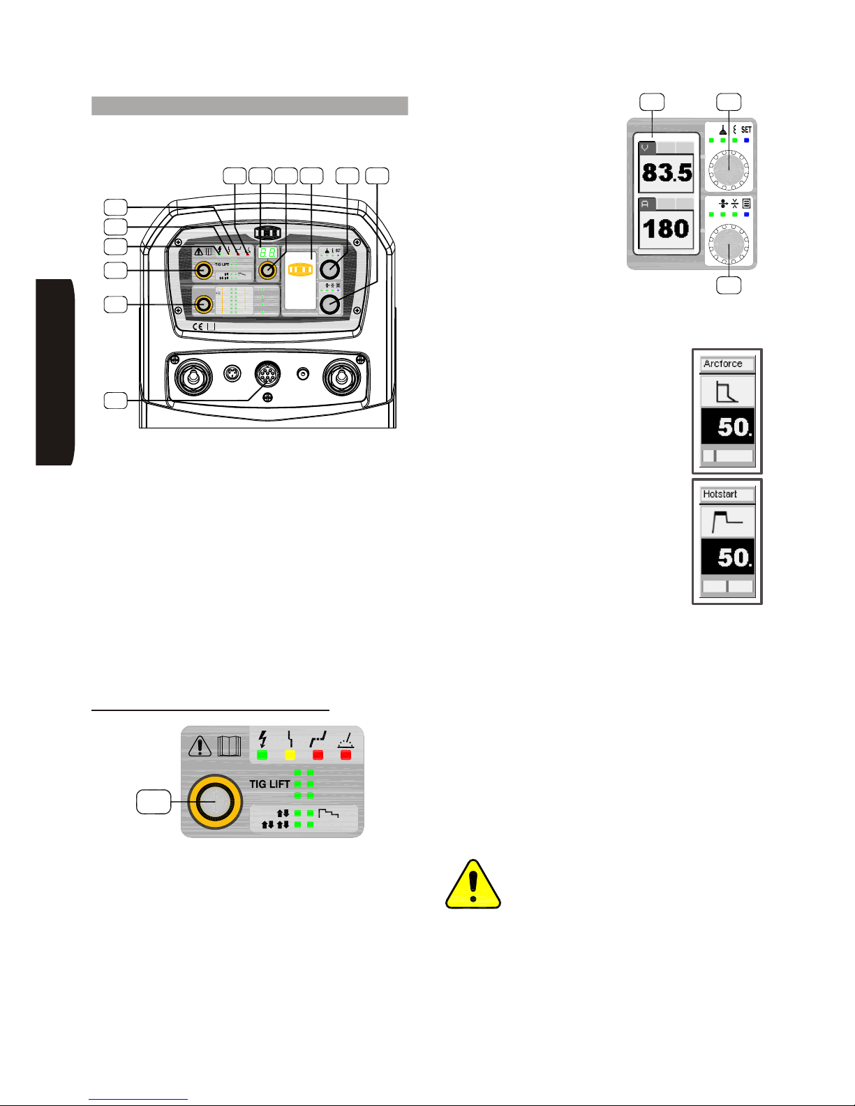
Page 38
INE S.p.A. Via Facca, 10 - 35013 Cittadella - PADOVA - ITALIA Tel. 049/9481111 - Fax 049/9400249 - [email protected] - www.ine.it
15 Settings through generator interface
The controls of the machine are described here below
with reference to the following figures.
The machine can be switched on by turning to its ON
position the main switch, located at the back of the
generator. When the machine is on, the ‘L1’ green LED
is lit.
The ‘L2’ yellow LED indicates that protection devices
have tripped (e.g. fuse blown), and display ‘D1’ shows
which one has actually tripped (see paragraph
‘Description of alarms’);
The ‘L3’ red LED indicates, in MIG/MAG, that with the
set parameters a welding in ‘Globular’ mode is being
executed; this mode is advised against fir the sake of
the final welding result.
The ‘L4’ red LED indicates the presence of output
voltage. In electrode, it is constantly lit; in TIG and in
MIG/MAG, it follows the course of the welding cycle.
15.1 Settings for MMA welding
The operating mode switch ‘S1’ allows the choice of the
welding mode.
• Press switch selector ‘E1’ for a while; the relevant led
will start blinking.
• Turn the selector until the led corresponding to the
MMA welding blinks (confirmation is automatic after
5 seconds of inactivity).
With selector switch ‘E5’ it is
possible to set at any time the
welding current, and its value
is shown on display ‘D1’. This
same display also shows,
while welding, the measured
voltage and current.
In MMA also you can set the following parameters:
• Hotstart HOT: percentage increase in
initial current; helps the electric arc
starting.
• Arcforce ARC: percentage increase in
welding current in the case of short
circuits; helps to prevent the shutdown
of the electric arc.
This procedure should be followed to change the former
parameters:
• Press switch selector ‘E4’ for 2 seconds; the blue led
‘SET’ will start blinking.
• Turn selector ‘E4’ to select the parameter to be
changed.
• Turn selector ‘E5’ to change its value (a slider at the
bottom of the display will show the setting range).
• Turn selector ‘E4’ to select any other parameter.
• After changing the desired parameters, press ‘E4’ to
exit ‘SET’ mode.
Attention: when choosing the MMA
welding, it is important, for avoiding risks and
dangerous situations, to check the position
of the MIG/MAG torch, as it will be energized
to the positive potential. (Thus you must avoid contact
with the piece being machined and with the earth
protection circuit.)
HSILGNE
KMP 5000
S
TIGHF
MMA
MIG DP
USER
MIG
MIGP
JOB
OK
A
ESC
V
AlSi
Flux
Rutil
ø1.0ø1.0
Ar
2
Cored
CuSi SPECIAL
AL
CuAl
AlMg
Metal
Wire
CrNi
ArCO
Basic
ø1.6ø1.6
ø1.2ø1.2
2
2
CO2SG2/3
SG2/3
CrNi Ar CO
NiCr ArHe
ø0.8ø0.8
kmp 5000
E5
L4 D1
E3
D2 E4
C5
L3
E2
L1
E1
L2
MMA
TIG HF
MIG P
MIG DP
MIG
USER
E1
OK
ESC
V
A
kmp 5000
D1 E4
E5
Page 41
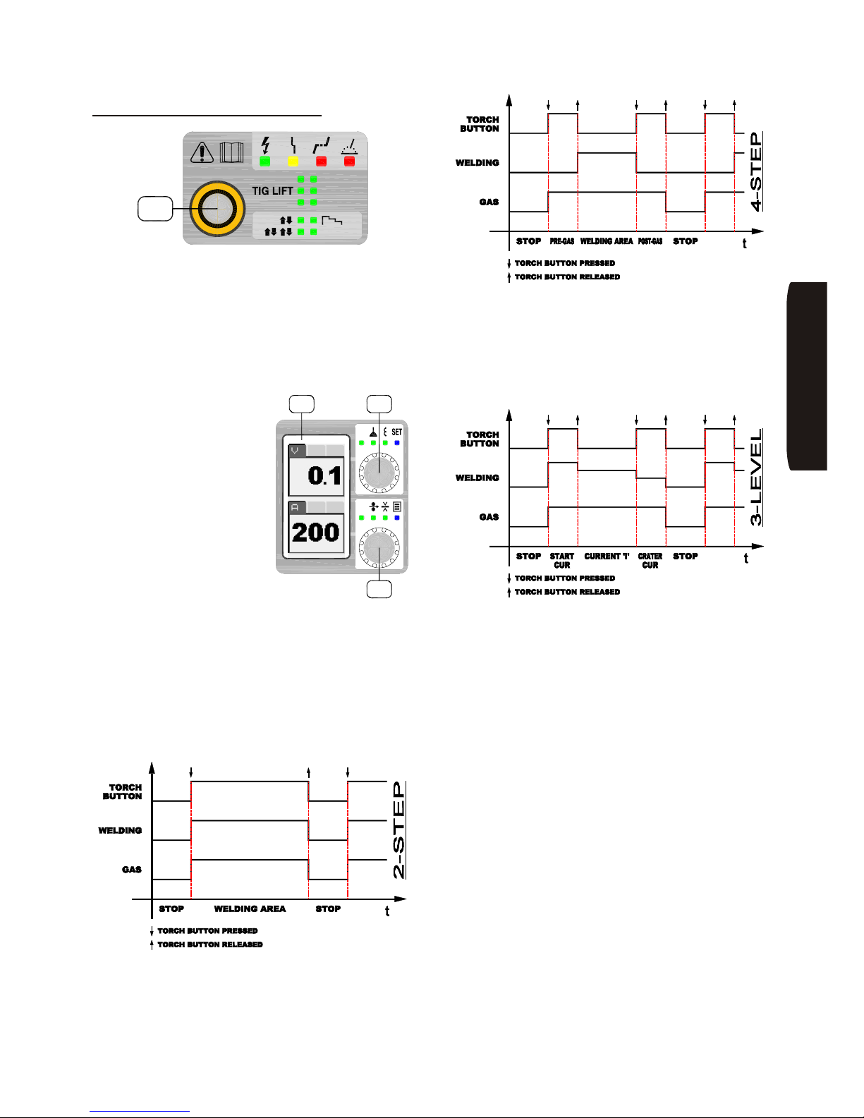
Page 39
INE S.p.A. Via Facca, 10 - 35013 Cittadella - PADOVA - ITALIA Tel. 049/9481111 - Fax 049/9400249 - [email protected] - www.ine.it
15.2 Settings for TIG welding
The operating mode switch ‘S1’ allows the choice of
the welding mode.
• Press switch selector ‘E1’ for a while; the relevant
led will start blinking.
• Turn the selector until the led corresponding to the
TIG LIFT or TIG HF welding blinks (confirmation is
automatic after 5 seconds of inactivity).
Con il selettore ‘E5’ è
possibile impostare in ogni
momento la corrente di
saldatura (in Ampere) e la
medesima è visualizzata sul
display ‘D1’.
Display ‘D1’ also shows, while
welding, the measured
voltage and current.
To select the operating mode:
• Press switch selector ‘E1’ for two times; the relevant
led will start blinking.
• Turn the knob until the led corresponding to the
mode wanted starts blinking. From the top left:
2-step (ÇÈ), 4-step (ÇÈÇÈ), 3-level or USER
mode (confirmation is automatic after 5 seconds of
inactivity).
2-step mode: the welding process starts when
pressing the torch pushbutton, and stops when
releasing it after the descent ramp has been executed
and the post-gas time is finished.
4-step mode: by pressing the torch pushbutton, the
welding process starts with a manual pre-gas; when
releasing it, actual welding will start. Upon the next
pressure of the torch pushbutton, the welding current
makes, if set, the descent ramp and then it will stop,
while the gas continues flowing; upon releasing it, the
gas flow will stop too.
3-level mode ]: when the torch trigger is pressed,
the welding process begins at the current value set with
parameter ‘Start cur’ (see explanation below). When
the torch trigger is released, the current will rise up to
the value set with ‘E5’. When the torch trigger is
pressed again, the current will drop down to the value
set with parameter ‘Crater cur’ (see explanation
below). When the torch trigger is released again, the
welding process will stop.
HSILGNE
OK
ESC
V
A
kmp 5000
D1 E4
E5
MMA
TIG HF
MIG P
MIG DP
MIG
USER
E1
Page 42
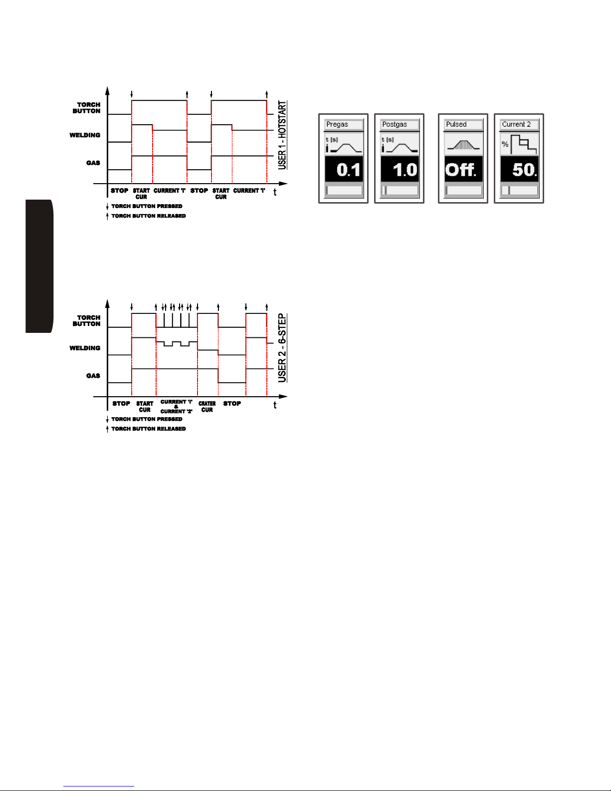
Page 40
INE S.p.A. Via Facca, 10 - 35013 Cittadella - PADOVA - ITALIA Tel. 049/9481111 - Fax 049/9400249 - [email protected] - www.ine.it
Another two modes are available if USER is selected:
Hotstart: when the torch trigger is pressed welding
begins (after the pre-gas time) at the current value set
with the ‘Start cur’ parameter and for the time set with
the ‘T-Hotstart’ parameter (see explanations below)
after which the current goes to the value set with ‘E5’.
When the torch trigger is released the process stops.
6-Step: when the torch trigger is pressed welding
begins at the current value set with the ‘Start cur’
parameter (see explanations below). When the trigger
is released the current goes to the value set with ‘E5’.
By pressing the torch trigger briefly you go to the
welding current set with the ‘Current 2’ parameter (see
explanations below). Another pulse takes the current
back to the value set with ‘E5’ and so on cyclically. To
finish the process you have to press the torch trigger:
the current goes to the value set with the ‘Crater cur’
parameter (see explanations below) and when the
trigger is released the process stops.
To select one of the two USER modes:
• Press selector ‘E5’ briefly; the blue led ‘3’ turns on
and the setup menu is displayed.
• Turn selector ‘E4’ to select the ‘User Mode’ page.
• Turn selector ‘E5’ to select the mode chosen and
confirm by pressing ‘E5’.
• Turn selector ‘E5’ to select ‘Exit’ and confirm by
pressing ‘E5’.
Within the same ‘SET’, it is possible to enter/adjust also
the following parameters (the figures here below are an
example of display boxes for setting the parameters):
• Pre-gas: pre-gas timing (seconds)
• Post-gas: post-gas timing (seconds)
• Up slope: current slope-up timing (seconds)
• Down Slope: current slope-down timing (seconds)
• Pulsed: current pulsing ON or OFF
• Base curr.: pulsed base current (Amps)
• Frequency: pulse frequency (Herz)
• Duty cycle: balance between welding current timing
and base current timing (e.g., a 50% duty cycle
means that welding current timing equals the base
current timing, a 30% duty cycle means that the
welding current timing is lower than the base current
timing)
• Start cur: initial current value / first level (for 3-level
or USER_6-T mode only)
• Crater cur: final current value / third level (for 3-level
or USER_6-T mode only)
• Hotstart: initial current value as a percentage of the
current value set with ‘E5’ (for the USER_Hotstart
mode only)
• T-Hotstart: duration of Hotstart (for the
USER_Hotstart mode only)
• Current 2: percentage of the current value set with
‘E5’ (for the USER_6-T mode only)
HSILGNE
Page 43
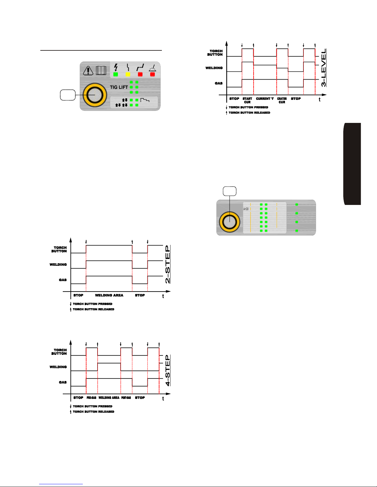
Page 41
INE S.p.A. Via Facca, 10 - 35013 Cittadella - PADOVA - ITALIA Tel. 049/9481111 - Fax 049/9400249 - [email protected] - www.ine.it
15.3 Settings for MIG /MAG welding
The operating mode switch ‘S1’ allows the choice of the
welding mode.
• Press switch selector ‘E1’ for a while; the relevant led
will start blinking.
• Turn the selector until the led corresponding to the
MIG, MIG P (pulsed) or MIG DP (double-pulsed)
welding blinks (confirmation is automatic after 5
seconds of inactivity).
To select the operating mode:
• Press switch selector ‘E1’ for two times; the relevant
led will start blinking.
• Turn the knob until the led corresponding to the
mode wanted starts blinking. From the top left:
2-step (ÇÈ), 4-step (ÇÈÇÈ) or 3-level mode
(confirmation is automatic after 5 seconds of
inactivity).
2-step mode: the welding process begins as soon as
the torch trigger is pressed and stops as soon as it is
released.
4-step mode: when the torch trigger is pressed, the
welding process begins with a manual pre-gas; when
released, the real welding begins. When the torch
trigger is pressed again, the welding will stop, although
gas will still flow; when released, also the manual
post-gas will stop.
3-level mode ]: when the torch trigger is pressed,
the welding process begins at the current value set with
parameter ‘Start cur’ (see explanation below). When
the torch trigger is released, the current will rise up to
the value set with ‘E5’. When the torch trigger is
pressed again, the current will drop down to the value
set with parameter ‘Crater cur’ (see explanation
below). When the torch trigger is released again, the
welding process will stop.
The type of wire and protection gas used are set with
selector ‘E2’ followed by the diameter of the wire. By
doing this, the synergic welding curve most suited to the
material chosen is selected (to exit the synergy preset
parameters please see the paragraphs below).
• Press selector ‘E2’ for a while; the relevant led will
start blinking.
• Turn the knob until the led corresponding to the type
of wire and gas you want to use starts blinking
(confirmation is automatic after 5 seconds of
inactivity).
To change the wire diameter:
• Press switch selector ‘E2’ for two times; the relevant
led will start blinking.
• Turn the knob until the led corresponding to the
diameter of the wire used starts blinking
(confirmation is automatic after 5 seconds of
inactivity).
HSILGNE
MMA
TIG HF
MIG P
MIG DP
MIG
USER
E1
ø1.0ø1.0
ø1.6ø1.6
ø1.2ø1.2
ø0.8ø0.8
Ar
SPECIALCuSi
ArHe
ArCO
Flux
ArCO
Wire
Cored
AlSi Rutil
AL
CuAl
AlMg
Metal
CrNi
Basic
SG2/3
SG2/3
NiCr
CrNi
2
2
E2
CO
2
2
Page 44
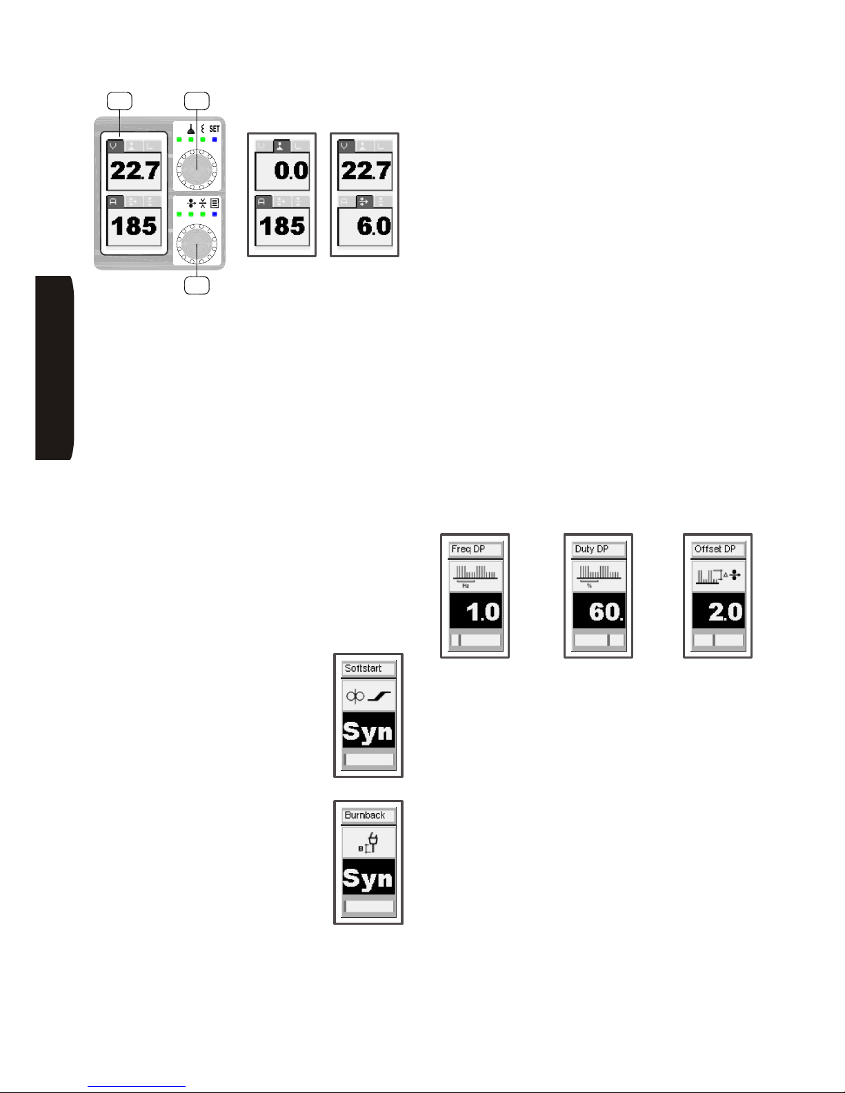
Page 42
INE S.p.A. Via Facca, 10 - 35013 Cittadella - PADOVA - ITALIA Tel. 049/9481111 - Fax 049/9400249 - [email protected] - www.ine.it
By pressing and turning selector ‘E4’ in sequence it is
possible to change the correction of the arc length and
the electronic inductance value for welding arc
stabilisation. To change these values:
• Press ‘E4’ in sequence for lighting the LED related to
the parameter to be modified, and rotate ‘E4’ for
changing its value.
The voltage parameter, ‘V’, can be set only in
non-synergic MIG/MAG (see the SET -> Synergy
function).
Selector switch ‘E5’ allows setting the welding current,
the wire speed and the piece thickness. For modifying
these values:
• Press ‘E5’ in sequence for lighting the LED related to
the parameter to be modified, and rotate ‘E7’ for
changing its value.
By keeping selector switch ‘E4’ pressed for more than
two seconds, you will go into the SET mode, where you
can set the following advanced parameters:
• Softstart: when the torch trigger is
pressed the wire is fed slowly, reaching
the set speed only when the welding
arc strikes. It is automatically adjusted
(‘Syn’ on the display) or adjustable from
1 to 100% of the speed set for the wire.
• Burnback: it adjusts power delay with
the aim of optimising the end of the
welding process (that is, the length of
the wire with respect to the end of the
torch). It is automatically adjusted
(‘Syn’ on the display) or adjustable from
1 to 100%.
• Pre-gas: pre-gas time (seconds)
• Post-gas: post-gas time (seconds
• Synergy: to turn the synergy mode ON or OFF. In
the manual mode it lets the user set all the
parameters exactly as they would be for traditional
MIG/MAG generators (adjustment of wire tension,
inductance and speed). This selection is not
available in MIG P or MIG DP because the
parameters need to be synergically controlled for a
correct pulsed arc welding.
Parameters that can only be set in MIG DP welding
(double-pulsed MIG):
• Freq DP: double-pulse frequency from a minimum of
0.1 Hz to a maximum of 5 Hz; this setting changes
the high/low pulses per cycle in Hz. The higher the
frequency the finer the ripple shape, the more
penetration is gained along with a higher speed of
pulses and travel speed
• Duty DP: this setting changes the % of the time the
high pulse is used, so resulting in a hotter weld with a
broader weld width
• Offset DP: sets the difference between the peak
current on the high and low pulse. The higher the
number increases the spacing between each ripple
shape. This setting is used in conjunction with the
Freq DP to obtain TIG like weld deposits
To change these parameters proceed as follows (the
figures shown above are an example of the screen
pages for setting the parameters):
• Turn selector ‘E4’ to select the parameter to change.
• Turn selector ‘E5’ to change its value (a scroll bar at
the bottom of the display gives you the setting
range).
• Turn selector ‘E4’ to select another parameter.
• When you have finished changing, press ‘E4’ to exit
the ‘SET’ mode.
The work return lead is to be connected to socket ‘A3’;
the torch to socket ‘A5’ and its cooling hoses to
connections ‘H2’.
HSILGNE
OK
ESC
V
A
kmp 5000
D1 E4
E5
Page 45
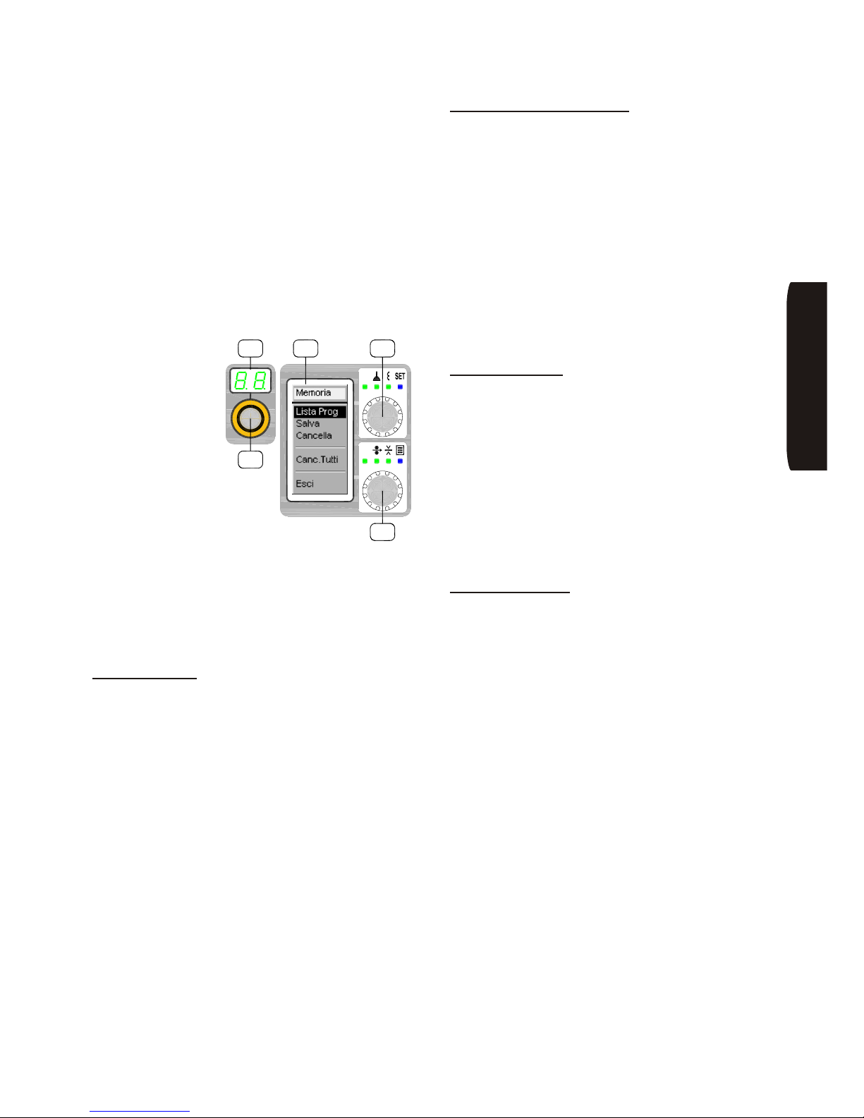
Page 43
INE S.p.A. Via Facca, 10 - 35013 Cittadella - PADOVA - ITALIA Tel. 049/9481111 - Fax 049/9400249 - [email protected] - www.ine.it
Concluding notes
By means of the connector ‘C5’ on the front panel, the
machine may be controlled using optional remote
controls. The selection of the remote control is
automatic when the connector is inserted and remains
in this way until it is physically disconnected.
The screensaver function is activated on the ‘D1’
display when the machine is not being used. To return
to normal viewing, simply turn any selector on the front
or press the torch trigger.
Storing programs
Personal welding
settings can be
stored in all welding
processes utilising
the ‘E5’ selector. Up
to a maximum of 100
programmes can be
stored.
After set all the desired parameters, access the
‘Memory’ menu:
• Press selector ‘E5’ briefly; the blue LED ‘3’ turns on
and the programmes memory management menu is
shown on the ‘D1’ display.
Turn selector ‘E5’ to select the option wanted:
Save a program:
• In the ‘Memory’ menu select ‘Save’.
• Press ‘E5’ and rotate knob ‘E3’ for selecting the
desired memory location (number), shown on
displays ‘D1’ and ‘D2’.
• If such chosen memory number is blinking on ‘D2’, it
means it is free. On the contrary, if it is steady lit, it
means that it is already occupied: in this case, by
continuing the operation, the programme that
existed there will be overwritten.
• Confirm your choice by pressing selector ‘E5’ or
cancel by pressing selector ‘E4’.
To exit from the ‘Memory’ menu press further ‘E4’ or
select ‘Exit’ turning ‘E5’ and confirm with pressing ‘E5’.
Load and modify a program:
• In the ‘Memory’ menu select ‘Load’.
• Press ‘E5’ and select, by turning ‘E3’, the memory
location (number) to be loaded, shown on displays
‘D1’ and ‘D2’ (if the memory number is blinking on
‘D2’, it means that the programme doesn’t exist).
• By pressing selector switch ‘E5’, the programme
present in the selected location will be loaded (it can
be modified and overwritten through the procedure
for saving a programme (described here above).
• Confirm your choice by pressing selector ‘E5’ or
cancel by pressing selector ‘E4’.
To exit from the ‘Memory’ menu press further ‘E4’ or
select ‘Exit’ turning ‘E5’ and confirm with pressing ‘E5’.
Delete a program:
• In the ‘Memory’ menu select ‘Delete’.
• Press ‘E5’ and select, by turning ‘E3’, the memory
location (number) to be deleted, shown on displays
‘D1’ and ‘D2’.
• Press ‘E5’: the programme present in that memory
location will be deleted.
• Confirm your choice by pressing selector ‘E5’ or
cancel by pressing selector ‘E4’.
To exit from the ‘Memory’ menu press further ‘E4’ or
select ‘Exit’ turning ‘E5’ and confirm with pressing ‘E5’.
Delete all program:
• In the ‘Memory’ menu select ‘Clear All’.
• Confirm your choice by pressing selector ‘E5’ or
cancel by pressing selector ‘E4’.
To exit from the ‘Memory’ menu press further ‘E4’ or
select ‘Exit’ turning ‘E5’ and confirm with pressing ‘E5’.
JOB
OK
ESC
V
A
kmp 5000
E3
D2 D1 E4
E5
HSILGNE
Page 46
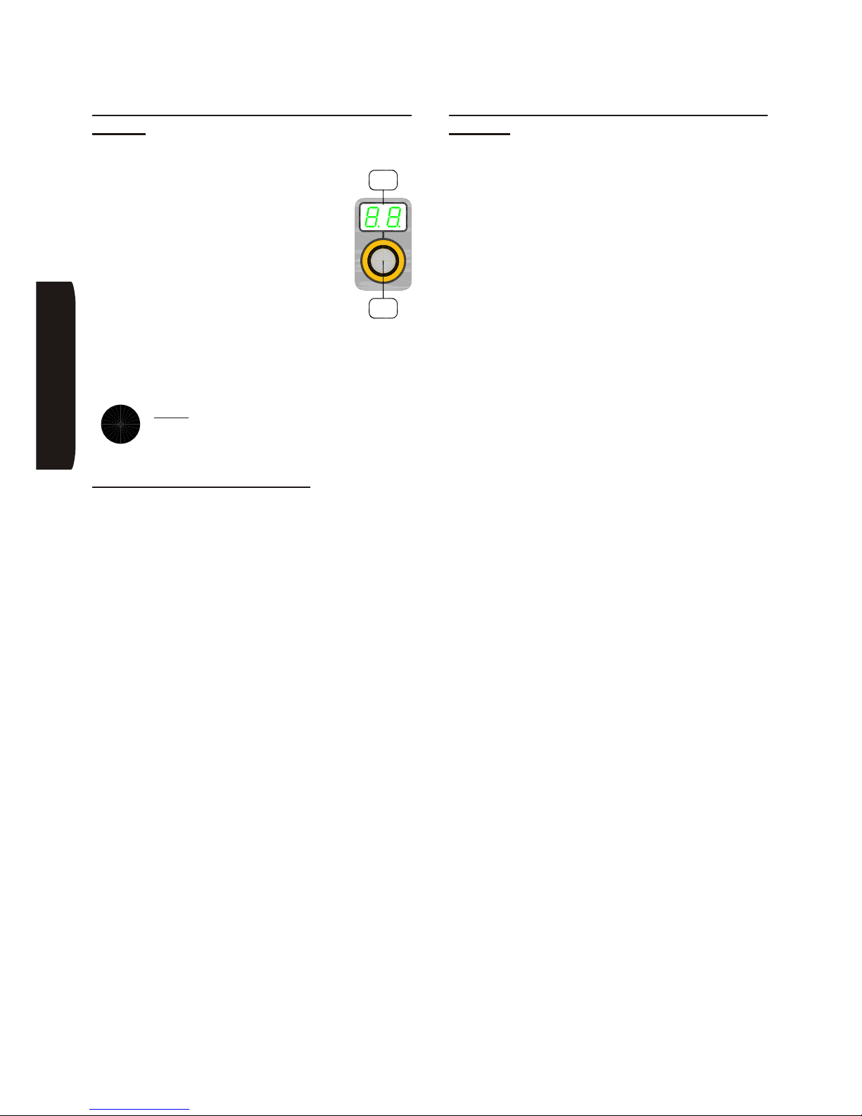
Page 44
INE S.p.A. Via Facca, 10 - 35013 Cittadella - PADOVA - ITALIA Tel. 049/9481111 - Fax 049/9400249 - [email protected] - www.ine.it
15.4 Fast programme selection (JOB
MODE)
To select a stored programme quickly:
• Press selector ‘E3’ for a while, display ‘D2’
shows the number of the first stored
programme available.
• Turn selector ‘E3’ to scroll the stored
programmes; the programme displayed is
automatically selected and immediately
active.
• The machine is blocked on the type of
welding and on the parameters set in the
stored programme.
To return to the normal operating mode, press selector
‘E3’ and 2 bars should appear on the ‘D2’ display
meaning that no programme is selected.
Note: when the machine is switched on it is
automatically set with the parameters that
were selected before it was switched off last.
15.5 Selecting the language
The user interface language can be selected. To
access the language selection menu:
• Press selector ‘E5’ briefly; the blue led ‘3’’ turns on.
• Turn selector ‘E4’ to select the ‘Language’ menu.
• Turn selector ‘E5’ to select the language wanted.
• Confirm your choice by pressing selector ‘E5’;
confirmation is shown when a dot appears near the
language chosen.
• Scroll the menu until you reach ‘Exit’ turning ‘E5’,
press ‘E5’ to exit the menu.
15.6 Software version and general
settings
It is possible to display the software version of the
machine, to zero set all the parameters so that they
become again the standard ones as delivered from the
factory, to manage the water chiller, and to display the
status of the basic counters of the machine, for example
the number of work hours, the number and date of the
alarms. For accessing the ‘SET’ menu:
• Press selector ‘E5’ briefly; the blue led ‘3’ turns on.
• Turn selector ‘E4’ to select the ‘Setup’ menu.
• Turn selector ‘E5’ to select the option wanted.
• To exit the selection function press ‘E5’, to cancel
press ‘E4’.
• Scroll the menu until you reach ‘Exit’ turning ‘E5’,
press ‘E5’ to exit the menu.
i
JOB
E3
D2
HSILGNE
Page 47
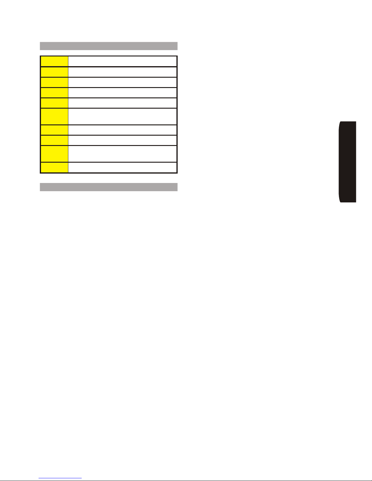
Page 45
INE S.p.A. Via Facca, 10 - 35013 Cittadella - PADOVA - ITALIA Tel. 049/9481111 - Fax 049/9400249 - [email protected] - www.ine.it
16 Description of alarms
AL1 Wire feed motor over current
AL2 Primary inverter module overheat
AL3 Secondary rectifier module overheat
AL4 Input voltage out of range
AL5 Cooling unit error
AL7
Torch pushbutton pressed in the course of
generator switch-on
AL8 Not compatible wire feeder
AL11 Indication of cooling unit voluntarily disabled
AL12
Indication of cooling unit voluntarily enbled is
not present
AL13 Logic board memory fault
17 Troubleshooting
A list of the possible failures of a SKYLINE KMP
generator is reported here below with the indication of
the possible causes.
A) The power source does not weld correctly. Check
that:
• the selector used to choose the type of welding is in
the right position
• the polarity in MIG/MAG welding is the one required
by the type of wire being used.
B) If when starting the machine the green LED ‘L1’ on
the front panel is on but the machine does not weld,
check that:
• check torch cable, power sockets, trolley/power
source extension and work return lead for integrity
C) If the machine stops and the yellow LED ‘L2’, when
welding, shows for over 4 minutes, check that:
• the air flow for the cooling of the components is not
hindered by dust or foreign objects placed in the
vicinity of the air vents
• the fan is working properly
D) It the machine works in MMA mode only, i.e. the red
LED ‘L3’ on the front panel does not show in MIG/MAG
mode, but in MMA mode only, check that:
• the electric contact of the torch trigger is properly
closed
E) Irregular welding:
• make sure there is no draft while welding
• make sure the gas flows regularly by checking gas
regulator, solenoid valve and connecting hoses
F) The wire feeding is irregular. Check:
• the wire spooling
• that the wire feed rollers are suited to the wire
diameter being used
• that the torch inlet is aligned with the wire feed roller
spline
• the torch liner making sure it is suited to the the
length and diameter of the wire being used; if
necessary, replace it
• the spool holder brake; if necessary, replace it
G) The wire sticks to the contact tip each time the
welding is stopped:
• adjust the power delay parameter (BURN-BACK). If
the time is too long, the wire will stick to the contact
tip; if it is too short, the wire will stick to the weld pool
HSILGNE
Page 48
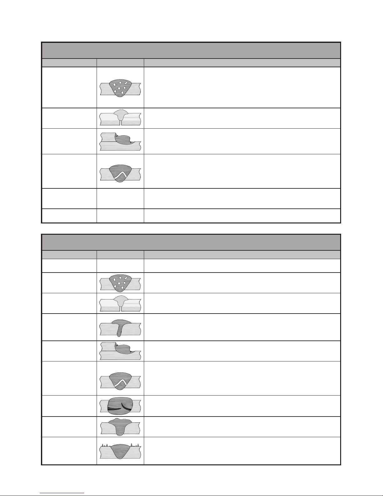
Page 46
INE S.p.A. Via Facca, 10 - 35013 Cittadella - PADOVA - ITALIA Tel. 049/9481111 - Fax 049/9400249 - [email protected] - www.ine.it
18 Possibili difetti di sald. in MMA e TIG
18 MMA & TIG: possible welding faults
Difetto / Fault Effetto / Effect Possibile causa / Possible cause
Porosità
Porosity
Sporcizia e/o ruggine / Dirt and/or rust
Velocità di saldatura e corrente elevate / Fast welding speed with high current
Corrente troppo bassa / Low current
Gas di protezione insufficiente / Insufficient shielding gas
Ugello troppo piccolo / Small nozzle
Arco troppo lungo / Long welding arc
Scarsa penetrazione
Poor penetration
Corrente troppo bassa / Low current
Velocità di saldatura elevata / Fast welding speed
Cianfrino troppo stretto / Narrow chamfer
Incisioni laterali
Lateral nicking
Velocità di saldatura lenta / Slow welding speed
Corrente troppo alta / High current
Diametro dell’elettrodo inadeguato comparato allo spessore del pezzo / Inadequate electrode
diameter compared to piece thickness
Cricche a caldo
Hot tears
Pezzo sporco / Dirty piece
Giunti troppo vincolati / Constrained joints
Saldatura con apporto termico elevato / Excessive heat
Materiale d’apporto non puro / Impure weld material
Materiale del pezzo con impurezze elevate / Workpiece with too many impurities
Inclusioni di tungsteno
Inclusions of tungstene
Affilatura scorretta dell’elettrodo / Incorrect electrode sharpening
Elettrodo troppo piccolo / Thin electrode
Contatto dell’elettrodo con il pezzo / Contact between electrode and workpiece
Ossidazioni
Oxidations
Mancata protezione a rovescio / Non-shielded backwelding
Gas di protezione insufficiente / Insufficient shielding gas
19 Possibili difetti di sald. in MIG/MAG
19 MIG/MAG: possible welding faults
Difetto / Fault Effetto / Effect Possibile causa / Possible cause
Arco instabile
Unstable arc
Controllare il flusso del gas / Check gas flow
Controllare il generatore / Check power source
Porosità
Porosity
Umidità nel gas / Wet gas
Sporcizia e/o ruggine / Dirt and/or rust
Arco troppo lungo / Excessive arc length
Scarsa penetrazione
Poor penetration
Corrente troppo bassa / Low current
Alimentazione del filo non costante / Inconstant wire feeding
Smusso troppo piccolo o lembi troppo distanti / Small bevel or distant edges
Scarsa fusione
Poor fusion
Movimenti oscillatori della torcia / Oscillating movements of the torch
Induttanza non ottimizzata / Non-optimised inductance
Tensione troppo bassa / Low voltage
Pezzo ossidato / Oxidised piece
Incisioni laterali
Lateral nicking
Velocità di saldatura eccessiva / Fast welding speed
Tensione troppo alta / High voltage
Cricche a caldo
Hot tears
Pezzo sporco / Dirty piece
Giunti troppo vincolati / Constrained joints
Saldatura con apporto termico elevato / Excessive heat
Materiale d’apporto non puro / Impure weld material
Materiale del pezzo con impurezze elevate / Workpiece with too many impurities
Rotture
Cracks
Tipo di filo non appropriato / Inadequate type of wire
Pezzi da saldare di scarsa qualità / Low quality workpieces
Difetti di profilo
Profile defect
Corrente troppo bassa / Low current
Sporgenza eccessiva del filo dalla torcia / Excessive protrusion of the wire from the torch nozzle
Spruzzi eccessivi
Excessive spatters
Induttanza non ottimizzata / Non-optimised inductance
Cappuccio sporco / Dirty cap
Torcia eccessivamente inclinata / Excessive slant of the torch
Tensione troppo alta / High voltage
Page 49

Page 47
INE S.p.A. Via Facca, 10 - 35013 Cittadella - PADOVA - ITALIA Tel. 049/9481111 - Fax 049/9400249 - [email protected] - www.ine.it
Page 50
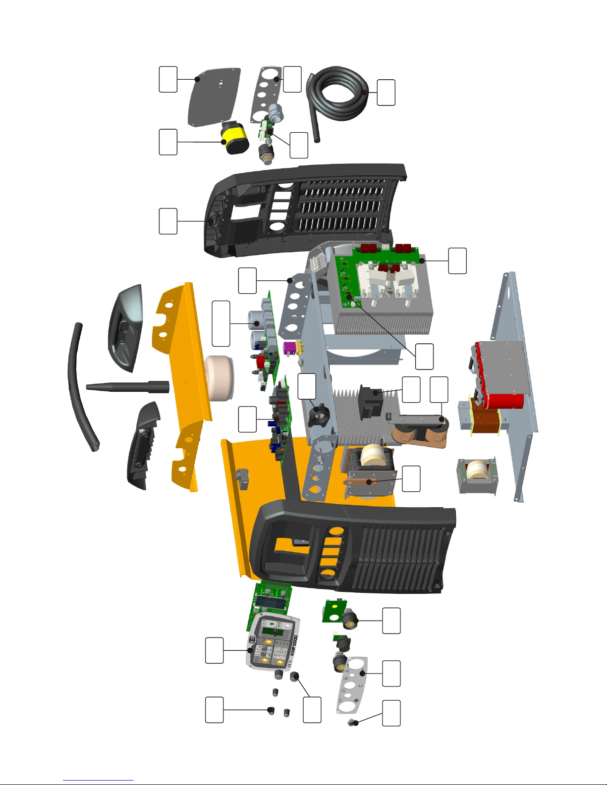
Page 48
INE S.p.A. Via Facca, 10 - 35013 Cittadella - PADOVA - ITALIA Tel. 049/9481111 - Fax 049/9400249 - [email protected] - www.ine.it
1 71 5
6
53
3
04414
33-23
31
91
8
32
03
13
41
73
83
12
22
Page 51
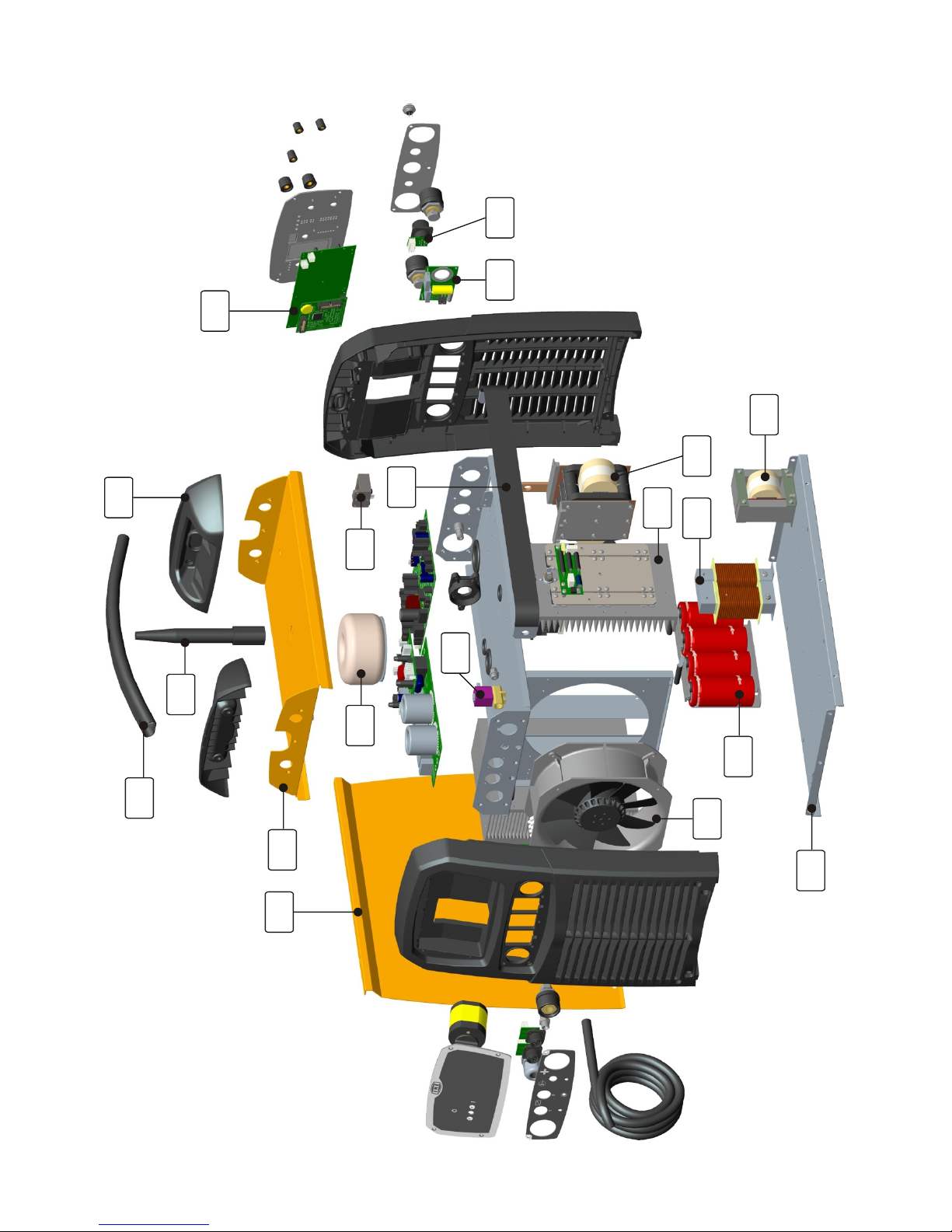
Page 49
INE S.p.A. Via Facca, 10 - 35013 Cittadella - PADOVA - ITALIA Tel. 049/9481111 - Fax 049/9400249 - [email protected] - www.ine.it
53 93
63
13 61
02
9
81
82
7
72
62
52
51
42
21
11
2
01
Page 52
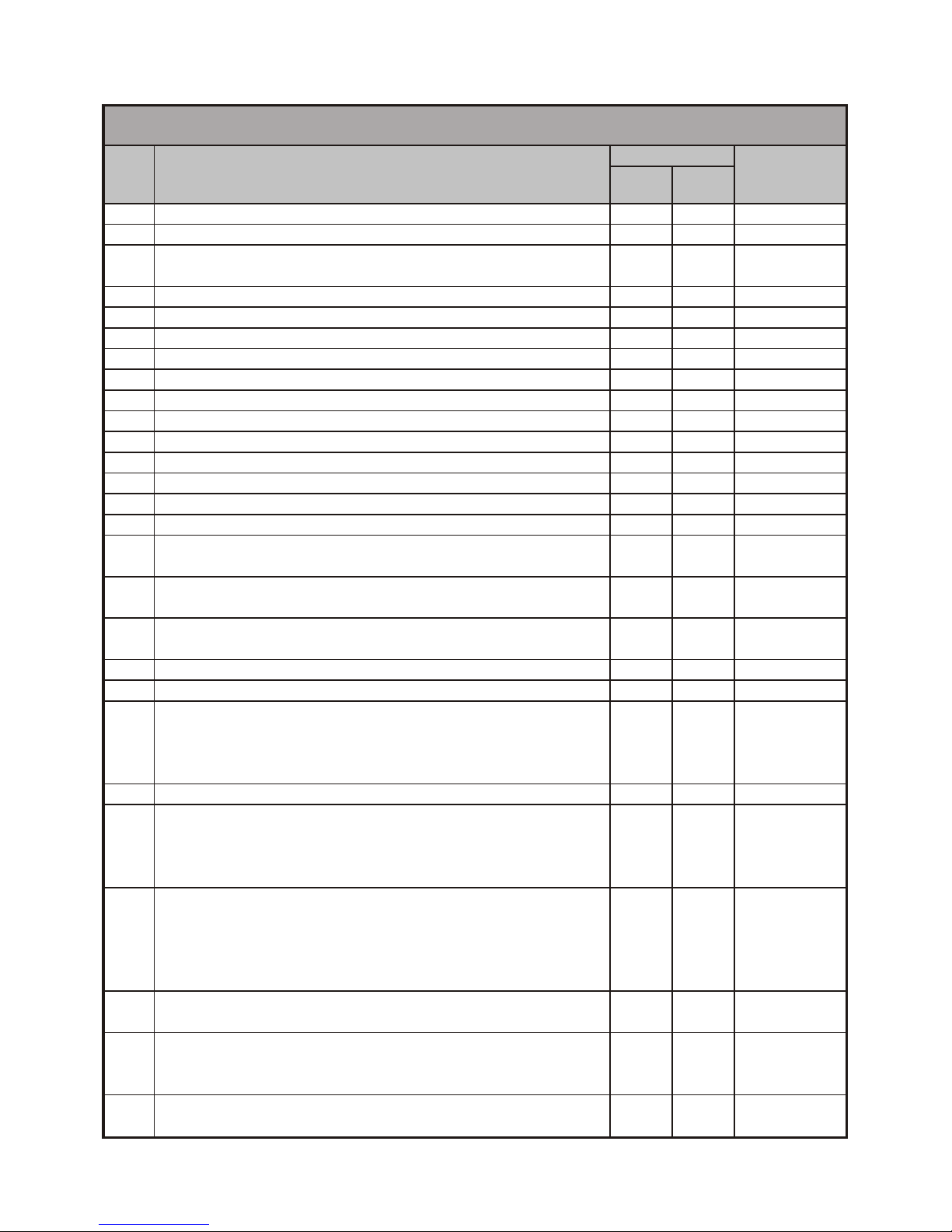
Page 50
INE S.p.A. Via Facca, 10 - 35013 Cittadella - PADOVA - ITALIA Tel. 049/9481111 - Fax 049/9400249 - [email protected] - www.ine.it
20 Parti di ricambio generatore
20 Spare parts for generator
Rif.
Item
Descrizione / Description
Q.tà/Q.ty
Codice/Part
number
MP04
KMP
3200
KMP
5000
1 Pannello frontale-posteriore / Front-rear panel 2 2 1050010
2 Copertura posteriore / Rear cover 2 2 1050015
3
Targa frontale up, KMP3200 / Front plate up, KMP3200
Targa frontale up, KMP5000 / Front plate up, KMP5000
1
-
-
1
0300457
0300448
4 Targa frontale down / Front plate, down 1 1 0300449
5 Targa posteriore up / Rear plate, up 1 1 0300450
6 Targa posteriore down / Rear plate, down 1 1 0300451
7 Pannello inferiore / Bottom panel 1 1 1050030
8 Pannello intermedio / Mid panel 1 1 1050035
9 Pannello laterale / Lateral panel 1 1 1050051
10 Pannello superiore / Top panel 1 1 1050060
11 Manico / Handle 1 1 1050070
12 Perno supporto carrello / Wire feeder pin support 1 1 1050090
13 Isolamento presa potenza HF / Insulation for HF socket 1 1 1050025
14 Barra rame / Copper bar 1 1 1050080
15 Barra presa positivo frontale-posteriore / Front-rear positive socket bar 1 1 1050085
16
Sensore hall 300A / Hall sensor, 300A
Sensore hall 500A / Hall sensor, 500A
1
-
-
1
8456001
8456004
17
Interruttore / Switch
Interruttore / Switch
1
-
-
1
0040119
0040120
18
Ventilatore ø150 / Fan, ø150
Ventilatore ø200 / Fan, ø200
1
-
-
1
0070048
0070049
19 Connettore femmina 6 poli / 6-pin connector, female 1 1 0050557
20 Elettrovalvola / Solenoid valve 1 1 0040290
21 Pressacavo / Cable clamp
Dado / Nut
Cavo alimentazione 4x4 mmq / Input cable, 4x4 mm
2
Cavo alimentazione 4x6 mmq / Input cable, 4x6 mm
2
1
1
1
-
1
1
-
1
0020238
0020239
0060610
0060615
22 Scheda ponti raddrizzatori / Rectifier bridges board 1 - 0050561
23A Modulo inverter primario / Primary inverter module
Scheda driver / Driver board
Modulo potenza / Power module
Condensatore / Condenser
1
1
2
2
-
-
-
-
2260200
0050518
8307003
8116482
23B Modulo inverter primario / Primary inverter module
Scheda ponti raddrizzatori / Rectifier bridges board
Scheda driver / Driver board
Modulo potenza / Power module
Condensatore / Condenser
-
-
-
-
-
1
1
1
2
2
1050200
0050561
0050518
8307003
8116482
24A Modulo raddrizzatore secondario / Secondary rectifier module
Diodo / Diode
1
3
-
-
1050210
8304000
24B Modulo raddrizzatore secondario / Secondary rectifier module
Diodo / Diode
Scheda snubber-clamp / Snubber-clamp board
-
-
-
1
6
1
2265210
8304000
0050547
25 Trasformatore / Transformer
1
-
-
1
1050270
1050260
Page 53
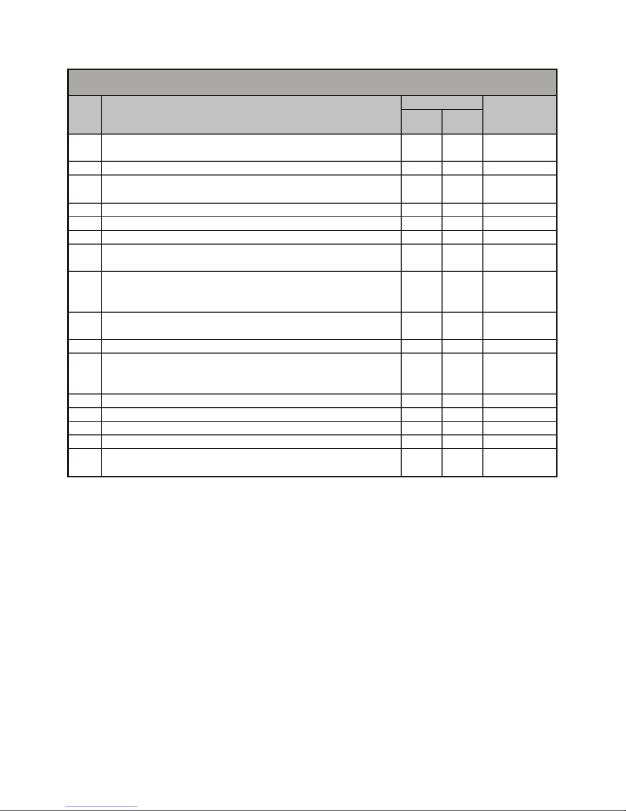
Page 51
INE S.p.A. Via Facca, 10 - 35013 Cittadella - PADOVA - ITALIA Tel. 049/9481111 - Fax 049/9400249 - [email protected] - www.ine.it
20 Parti di ricambio generatore
20 Spare parts for generator
Rif.
Item
Descrizione / Description
Q.tà/Q.ty
Codice/Part
number
MP04
KMP
3200
KMP
5000
26 Induttanza / Inductance
1
-
-
1
2260225
2265225
27 Induttanza primario / Inductance for primary 1 1 1050160
28
Condensatore / Condenser
Resistore 22kW 10W / Resistor, 22KW 10W
1
1
4
2
0050057
8232320
29 Scheda H.F. / H.F. board 1 1 0050007
30 Trasformatore H.F. / H.F. Transformer 1 1 2266210
31 Trasformatore ausiliario / Auxiliary transformer 1 1 0040024
32 Scheda ingresso / Entrance board
1
-
-
1
0050568
0050562
33 Scheda allarmi / Alarm board
Fusibile 5x20 - 3,15A / Fuse, 5x20 - 3.15A
Fusibile 5x20 - 6,3A / Fuse, 5x20 - 6.3A
1
2
1
1
2
1
0050563
0040350
0040351
34 Scheda logica / Logic board
Fusibile 5x20 - 1A / Fuse, 5x20 - 1A
1
1
1
1
0050534
0040345
35 Scheda filtro / Filter board 1 1 0050560
36 Scheda frontale / Front board
Scheda interfaccia uP / uP interface board
Display grafico / Graphical display
1
1
1
1
1
1
0050538
0050515
8402005
37 Manopola ø22 / Knob, ø22 2 2 0040168
38 Manopola ø15 / Knob, ø15 3 3 0040169
39 Connettore femmina 10 poli / 10-pin connector, female 1 1 0050558
40 Presa attacco rapido 70 mmq / Quick connection, 70mm
2
3 3 0040266
41 Connettore femmina 3 poli / 3-pin connector, female
Connettore maschio 3 poli / 3-pin connector, male
1
1
1
1
0040249
0040248
Page 54
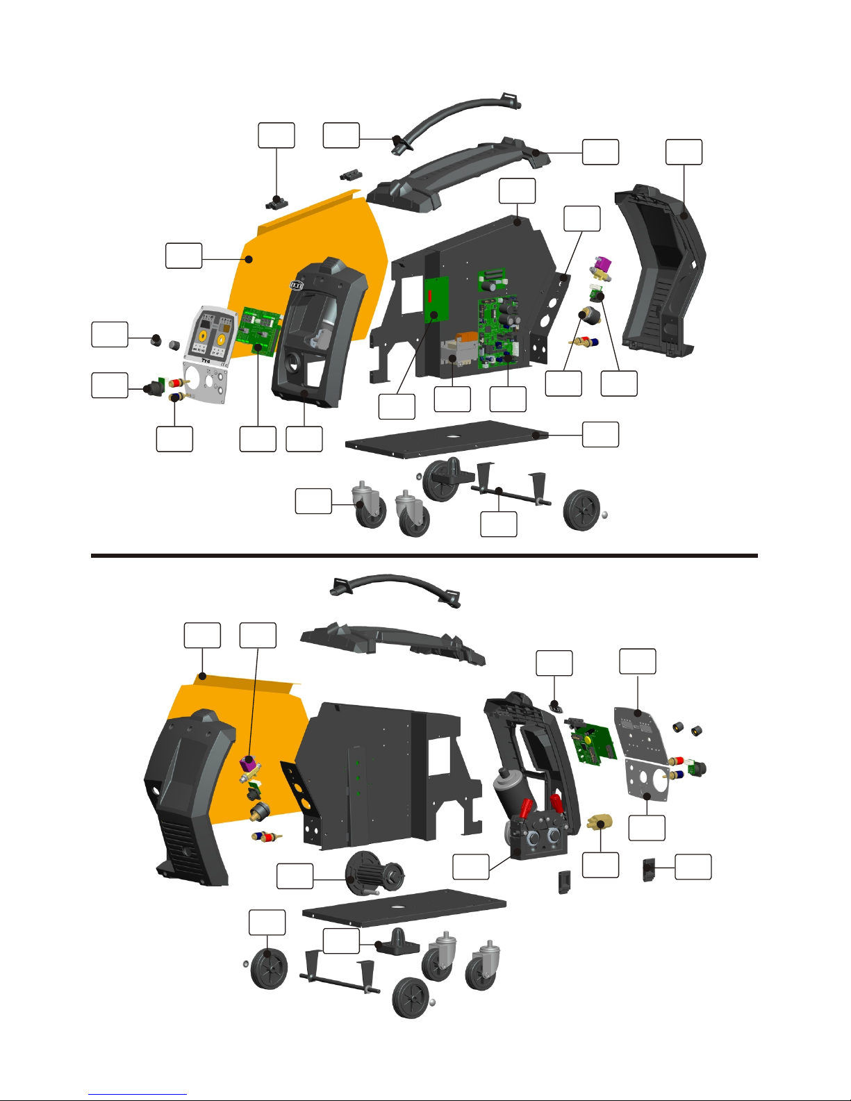
Page 52
INE S.p.A. Via Facca, 10 - 35013 Cittadella - PADOVA - ITALIA Tel. 049/9481111 - Fax 049/9400249 - [email protected] - www.ine.it
13 6
5
12
27
4
31
28
126
7
3
10
23 24
9
17
16
18
20
11
25
19
8
14
2
15
22
30
29
21
Page 55
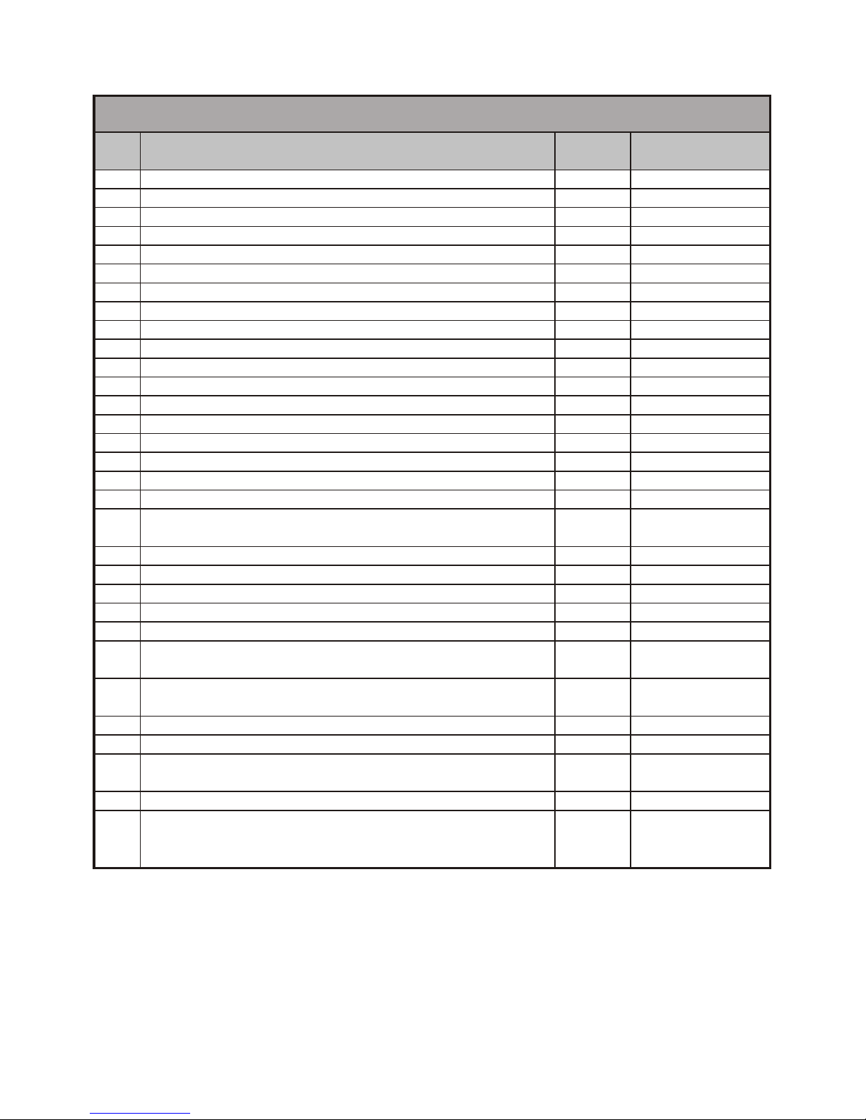
Page 53
INE S.p.A. Via Facca, 10 - 35013 Cittadella - PADOVA - ITALIA Tel. 049/9481111 - Fax 049/9400249 - [email protected] - www.ine.it
21 Parti di ricambio trainafilo TY4
21 Spare parts for TY4 wire feeder
Rif.
Item
Descrizione / Description
Q.tà/Q.ty
Codice/Part number
(MP04)
1 Pannello frontale / Front panel 1 1460010
2 Etichetta adesiva INE / INE sticker 1 0300306
3 Targa frontale up / Front plate, up 1 0300454
4 Targa frontale down / Front plate, down 1 0300455
5 Pannello superiore / Top panel 1 1460015
6 Manico / Handle 1 1460070
7 Pannello posteriore / Rear panel 1 1460020
8 Boccola isolante / Insulation washer 1 1460025
9 Basamento / Base 1 1460030
10 Pannello intermedio / Partition panel 1 1460040
11 Supporto prese / Sockets support 1 1460045
12 Pannello laterale Dx / Lateral panel, right 1 1460051
13 Cerniera / Hinge 2 0300160
14 Chiusura a spinta / Slide latch 2 0020258
15 Pannello laterale Sx / Lateral panel, left 1 1460061
16 Alberino per ruota / Wheel shaft 1 1460080
17 Ruota fissa / Fixed wheel 2 0020120
18 Ruota girevole / Shivel wheel 2 0020110
19 Rocchetto portabobina / Spool holder
Ghiera filettata / Ring nut
1
1
0020200
0020202
20 Connettore femmina 6 poli / 6-pin connector, female 1 0050557
21 Elettrovalvola / Solenoid valve 1 0040290
22 Spina da pannello 70 mmq / Panel plug, 70 mm
2
1 0040269
23 Trasformatore / Transformer 1 0040005
24 Scheda logica di controllo / Logic control board 1 0050565
25 Scheda modalità / Mode board
Serigrafia adesiva TY4-KMP / Self-sticking serigraphy, TY4-KMP
1
1
0050564
0300456
26 Scheda frontale / Front board
Scheda interfaccia uP / uP interface board
1
1
0050559
0050515
27 Manopola ø22 / Knob, ø22 2 0040168
28 Connettore femmina 10 poli / 10-pin connector, female 1 0050558
29 Attacco torcia EURO / Torch connection, EURO
Tubetto 5x2x51 / Tube 5x2x51
1
1
0072080
0072090
30 Motoriduttore completo 4R / 4R gearmotor, complete 1 0072045
31 Raccordo rapido femm. x acqua / Quick water connection, female
Fascetta / Strip
Tubo retinato ø11 / Grid hose, ø11
4
4
*
0020407
0020454
0300002
Page 56
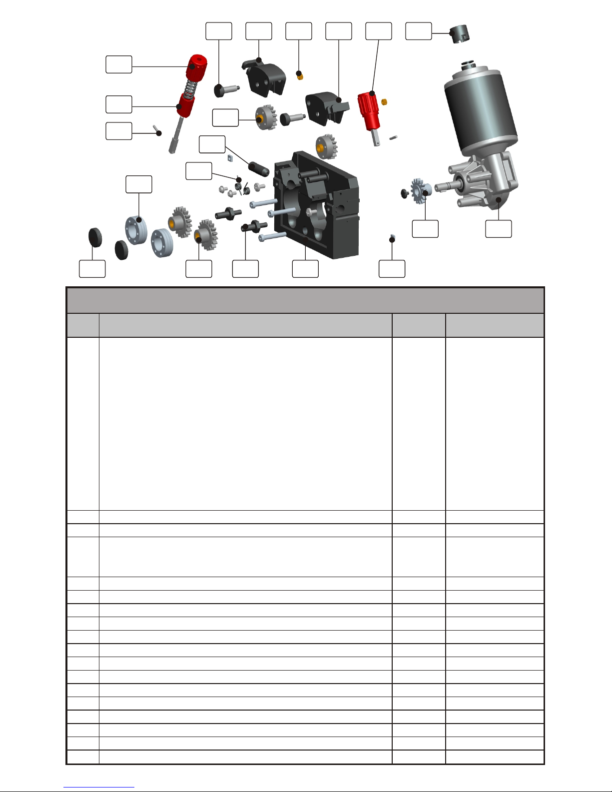
2
4
1
6
3
5
4.1
4.2
7
8 910
11
12
13
14 15 16
17
18
22 Ricambi trainafilo 4 rulli
22 Spare parts for 4-roller wire feed
Rif.
Item
Descrizione / Description Q.tà/Q.ty
Codice/Part number
(MP04)
1 Rullino ø0.6-0.8 / Roller, ø0.6-0.8
Rullino ø0.8-1.0 / Roller, ø0.8-1.0
Rullino ø1.0-1.0 / Roller, ø1.0-1.0
Rullino ø1.0-1.2 / Roller, ø1.0-1.2
Rullino ø1.2-1.2 / Roller, ø1.2-1.2
Rullino ø1.2-1.6 / Roller, ø1.2-1.6
Rullino per alluminio ø0.8-1.0 / Roller for aluminium, ø0.8-1.0
Rullino per alluminio ø1.0-1.2 / Roller for aluminium, ø1.0-1.2
Rullino per alluminio ø1.2-1.6 / Roller for aluminium, ø1.2-1.6
Rullino per alluminio ø1.6-2.4 / Roller for aluminium, ø1.6-2.4
Rullino per filo animato ø0.9-1.2 / Roller for cored wire, ø0.9-1.2
Rullino per filo animato ø1.2-1.4 / Roller for cored wire, ø1.2-1.4
Rullino per filo animato ø1.6-2.4 / Roller for cored wire, ø1.6-2.4
2
2
2
2
2
2
2
2
2
2
2
2
2
0072100
0072101
0072102
0072103
0072104
0072105
0072110
0072111
0072112
0072113
0072120
0072121
0072122
2 Bussola guidafilo / Wire guide bush 1 0072150
3 Dado quadro M5 / Square nut M5 2 0072160
4
4.1
4.2
Gruppo pressione completo / Wire pressure unit, complete
Manopola rossa / Red knob
Base graduata per manopola / Base graduated knob
2
2
2
0072170
0072172
0072174
5 Spina 3x16 / Pin 3x16 2 0072180
6 Inserto ottone M5 / Brass insert M5 2 0072190
7 Base plastica traino 4R / Plastic base wire feed 4R 1 0072250
8 Braccio premifilo Sx / Pressure arm left 1 0072252
9 Braccio premifilo Dx / Pressure arm right 1 0072254
10 Vite supporto rullo superiore 4R / Top roller support screw 4R 2 0072256
11 Molla braccio premifilo / Pressure arm spring 2 0072258
12 Rullo + ingranaggio superiore ø30 / Top roller + gear ø30 2 0072260
13 Ingranaggio centrale ø30 / Central gear ø30 1 0072262
14 Vite bloccaggio rullo inferiore / Fixing screw bottom roller 2 0072264
15 Ingranaggio inferiore ø37 / Bottom gear ø37 2 0072266
16 Asse ingranaggio inferiore / Axle bottom gear 2 0072268
17 Motore 42V-100W con encoder / 42V-100W motor with encoder 1 0072280
18 Encoder / Encoder 1 0072290
Page 57
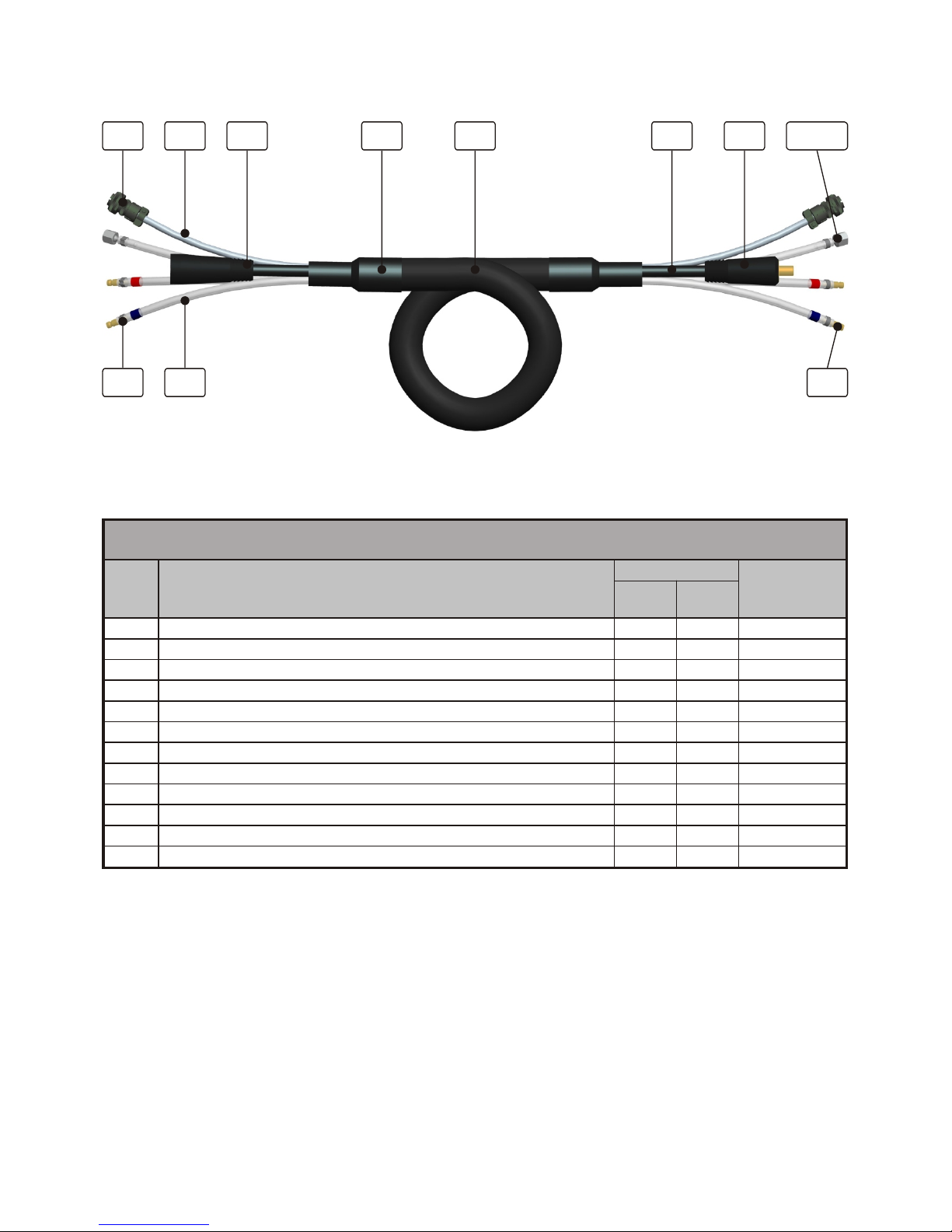
Page 55
INE S.p.A. Via Facca, 10 - 35013 Cittadella - PADOVA - ITALIA Tel. 049/9481111 - Fax 049/9400249 - [email protected] - www.ine.it
23 Parti di ricambio prolunga generatore-carrello
23 Spare parts for generator-wire feeder extension
Rif.
Item
Descrizione / Description
Q.tà/Q.ty
Codice/Part
number
MP04
AIR H2O
1 Spina 70mmq / Socket, 70 mm
2
1 1 0040276
2 Presa 70 mmq / Plug, 70 mm
2
1 1 0040279
3 Corda saldatrice 70 mmq / Welding cable, 70 mm
2
* * 0060204
4 Portagomma / Rubber holder 2 2 0020381
5 Dado per portagomma / Nut for rubber holder 2 2 0020382
6 Tubo retinato ø11 / Grid pipe, ø11 * * 0300002
7 Fascetta / Strip 2 6 0020454
8 Raccordo rapido maschio x acqua / Quick water connection, male - 4 0020409
9 Connettore maschio 6 poli / 6-pin connector, male 2 2 0040233
10 Cavo 7 vie / Cable, 7-way 1 1 0060061
11 Guaina per prolunga / Sheath for extension * * 0300012
12 Guaina termorestringente / Sheath for extension 2 2 0300005
* La quantità va specificata insieme al codice di ordinazione / Quantity and article number to be specified in the purchase order
9
8
2 4-5112 11 310
67
Page 58
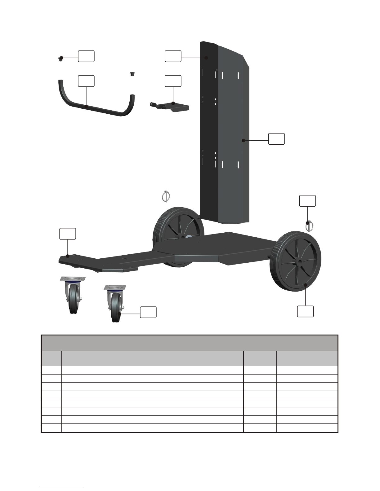
Page 56
INE S.p.A. Via Facca, 10 - 35013 Cittadella - PADOVA - ITALIA Tel. 049/9481111 - Fax 049/9400249 - [email protected] - www.ine.it
24 Ricambi carrello portageneratore PR8 (cod. PFCS1000160)
24 Spare parts for PR8 generator trolley (P/N PFCS1000160)
Rif.
Item
Descrizione / Description Q.tà/Q.ty
Codice/Part number
(MP04)
1 Basamento / Base 1 1480010
2 Supporto bombola / Bottle support 1 1480020
3 Distanziale / Spacer 1 1480030
4 Ruota fissa ø250 / Fixed wheel, ø250 2 0020150
5 Copiglia ø4 / Split pin, ø4 2 0201075
6 Ruota girevole ø125 / Shivel wheel, ø125 2 0020020
7 Supporto per cavi / Cables support 1 1480040
8 Tappo / Stopper 2 0300201
5
1
5
3
4
2
6
7
8
Page 59

Page 57
INE S.p.A. Via Facca, 10 - 35013 Cittadella - PADOVA - ITALIA Tel. 049/9481111 - Fax 049/9400249 - [email protected] - www.ine.it
Page 60
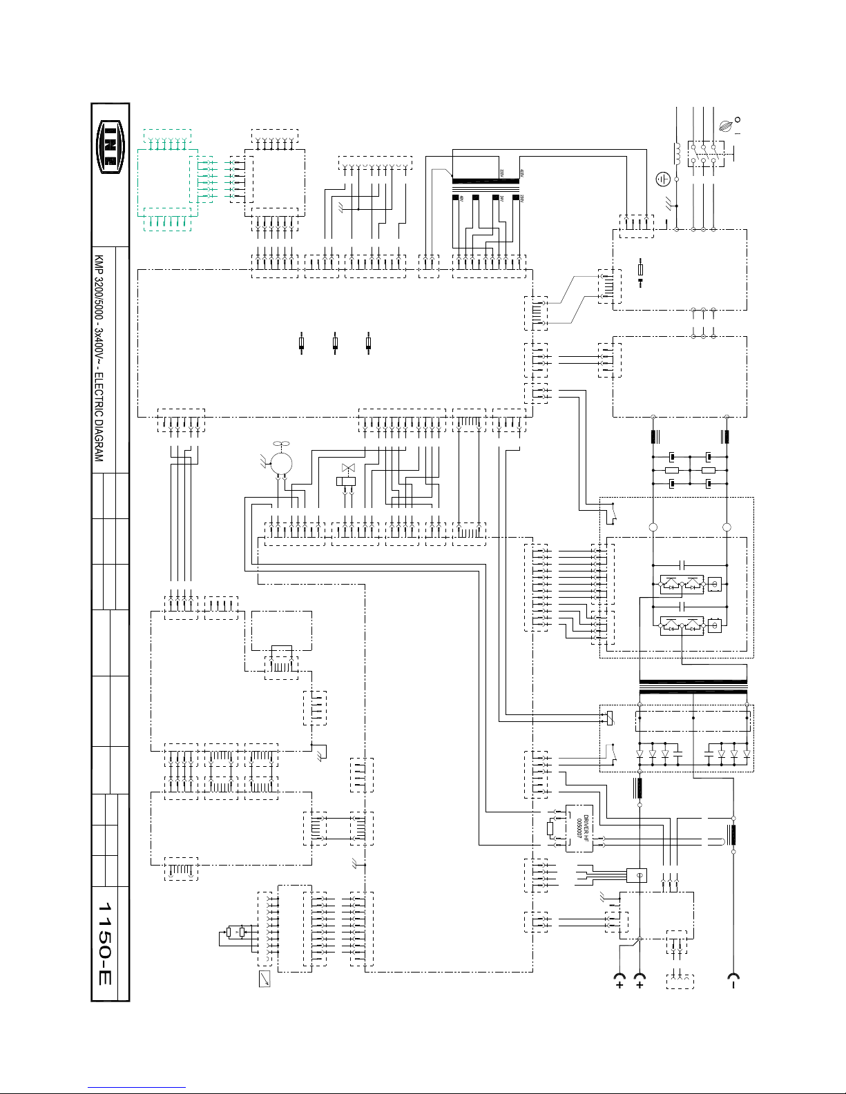
Page 58
INE S.p.A. Via Facca, 10 - 35013 Cittadella - PADOVA - ITALIA Tel. 049/9481111 - Fax 049/9400249 - [email protected] - www.ine.it
25 Schemi elettrici 25 Electric diagrams
Cod.
Title
MODIFY DESIGNER CONTROLLER
REPLACES
REPLACES BY N.
DESIGNER
SUPERVISOR
DATE
DATE
PAGING
FIRST P.THIS P. LAST P.
PLAN NUMBER
THIS PLAN IS OWNED BY I .N.E s.p.a. UNAUTHORIZED REPRODUCTION OR DIFFUSION PROHIBITED.
INDUSTRIA
NAZIONALE
ELETTRODI
20.01.2014
A A A
PFCSKP320A00 - PFCSKP500A00
Camilli L.
Tombolato A.
3
1
3
2
6
46
6
EL1
~
PE
CN10
2
1
21
CN5
1~
M
42
21
CN12
41
43
5
4443 45
21
T1
43
5
-VBUS
+VBUS
PE
CN4
0050538 BOARD
CN5
CN1
1
40
4
2
3 3
412
40
CN7
CN2
CN3
1
26
CN2
CN4
1
20
0050570 BOARD (KMP3200)
4 1
CN2
20
1
1
40
1
40
1
CN1
1
CN3
3
2 4
DISPLAY
128x64
1
30
CN5
3
4
2
1
1
10
50
87 9
4847 49
1211
5251
TM-
CN1
8
CN2
7 1 2 3 4
2
TR2
3
5
6
CN3
4
3938 53
12
54
GRAY
YELLOW
VIOLET
BROWN
1
CN1
32 4
T2
L3
HALL
TM+
3
230Vac
1
CN4
2
6362
58 59
21
CN2
5756
HF
0050568 BOARD (KMP3200)
1
CN1
10
1
432
FT31.5
6 SPIRE
PE
W
5 6
U
V
3
1
I1
2
4
S-INPET-IN
R-IN
FN1
+VBUS
SOUT
TOUT
ROUT
11
12
10
SIN
TIN
RIN
+
--VBUS
CN2
CN11
1
2
10
CN6
1
2
1
CN5
4
3
CN3
1 2
3 4
CN2
33
1 2
32
3 4
587
6
1
432
CN12
5886
1
2
3
4
CN8
848587
10
98765
12
11
4
3
2
1
9
1
2
876
5
4
3
10
CN9
F1 (10AT)
F4 (3.15AT)
F6 (3.15AT)
PE
NEG.
POS.
POS
PE.
55
0050560 BOARD
61
60
CN1
1
2
PT-TIG
2
1
3
NEG
54
53
55
F
E
GNDCAN
048VAC
C
B
A
D
48VAC
+VCAN
CANH
CANL
0V
TR1
0V0V0V
0V
8V
0050561 BOARD
CN10
89
10230V_PUMP
230V_PUMP
230V_VENT
0230V_VENT
8
CONTROL
COOLING
PE
9105
FL2
6
7
FL1
3
2
4
868370
40
90 90
898683
412
3
70
40
1
10
CN3
10
1
CN13
0050563 BOARD
4
3
1
2
CN4
CN9
82 80
3
4
1
2
CN6
6
5
6
543
2
1
CN11
8
7
653
4
CN7
2
1
64
3
4
CN6
2
1
888587
84
2
35
1
34
CN1
0050518 BOARD
6
4
3
5
2
1
CN1
PT1
0050515 BOARD
6566676869
81
80
79777674737175
37
36
74
768275
81
797330
25
71
7859777258
POT.EXT.
GNDCAN
CANL
CANH
+VCAN
2K5
MAX
*
MIN
2K5
MAX
MIN
0050558 BOARD
CN1
A B C D E F G H
1 2
3
4
5
6 7 8
CN7
9291 9493 95 96 9897
1 2
3
4
5
6 7 8
I
J
9 10
99
9 10
PE
WIRE FEEDER
COOLING PUMP
COOLING FAN
22
23
21
TRANSFORMER
PRIMARY AUX
F1 (3.15AT)
2
1
5
3 4
2
6
CN2
0050557 BOARD
CANL
CANH
GNDCAN
+VCAN
48VAC
048VAC
0050557 BOARD
F
D
E
C
1
A
B
6
345
CN1
1
2
CN2
1 2
3
5
4
6
13 1614 15 17 18
L1
L1
0050562 BOARD (KMP5000)
0050571 BOARD (KMP5000)
(only on KME5000)
0050547 BOARD
Page 61
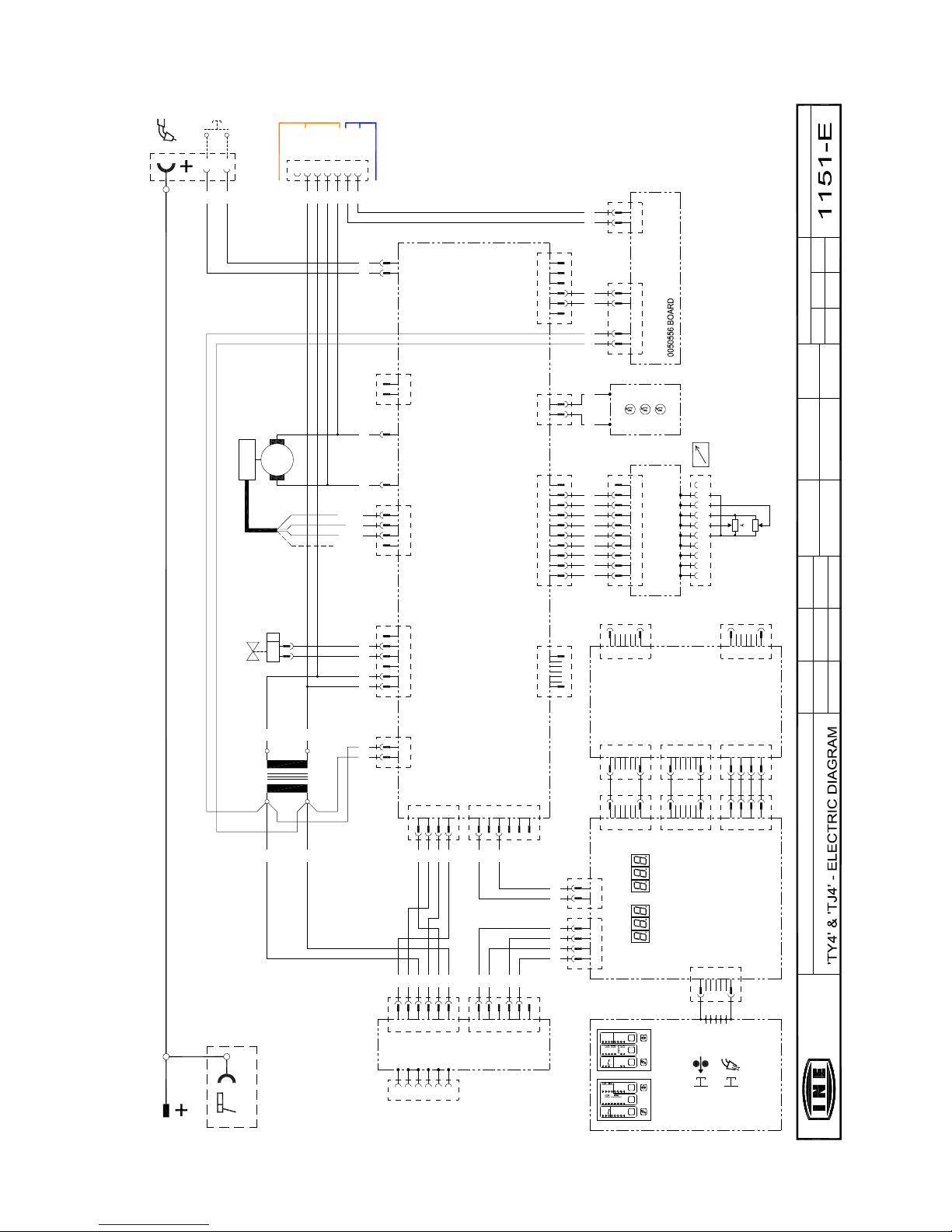
Page 59
INE S.p.A. Via Facca, 10 - 35013 Cittadella - PADOVA - ITALIA Tel. 049/9481111 - Fax 049/9400249 - [email protected] - www.ine.it
Cod.
Title
MODIFY DESIGNER CONTROLLER
REPLACES
REPLACES BY N.
DESIGNER
SUPERVISOR
DATE
DATE
PAGING
FIRST P.THIS P. LAST P.
PLAN NUMBER
THIS PLAN IS OWNED BY I.N.E s.p.a. UNAUTHORIZED REPRODUCTION OR DIFFUSION PROHIBITED.
INDUSTRIA
NAZIONALE
ELETTRODI
03.12.2014
A A A
PFCS 128414-1280524-1300414-1300524
Camilli L.
Tombolato A.
98 99
9 10
94 96 979592 9391
4
5
76 8
1
3
2
CN1
7 8 1096
5
42
3
1
2K5
GNDCAN
POT.EXT.
MIN
2K5
*
MAX
G H I
J
MIN
E FD
MAX
A CB
CANL
+VCAN
CANH
0050558 BOARD
33
32
1
2
PT
70 mm2
CN2
1 2
2623
CN2
1
20
CC
M
30
+MOT
31
-MOT
18 17
EL1
~
2827
CN7
1 2
3
4
5
6
PT1
PT2
CN8
3332
212
CN1
1
3
4
ENCODER
0050565 BOARD
19
10
17
18
2
CN3
1
10 19
CN2
41 2
3
61 60
1
2
3
1
3
2
CPP
19 10
31
173018
4
567
PUSH-PULL RITTER
PUSH-PULL BINZEL
042Vcc
024Vac
48Vcc
048Vcc
24Vac
42Vcc
62
2
CN1
1
63
62
63
YELLOW
BLACK
RED
GREEN
CN6
CANL
CANH
+VCAN
48VAC
048VAC
GNDCAN
5
3
4
6
0050557 BOARD
C
D
E
F
A
B
3
CN2
1
2
5
4
6
CN1
1
2
25
242122
0050559 BOARD
20
CN1
2
3
4
CN6
CN5
CN4
40
1
1
40
1
1
2
4
3
26
CN5
CN1
40
1
1
CN3
40
1
CN2
1
20
CN4
1
0050515 BOARD
0050564 BOARD
20
1
3
2
1
4
CN5
1
2
23
26
11
14
CN0
4
CN3
21
3
25 2122 24
3
4
5
6
15
12
AV
191510
141112
48V
0V
24V
0V
T1
4
+LED
CN4
BLACK RED
1 2
LED
-LED
5
6
only TJ4
PRG
KME
ø0.8
AlMg
1
MIG
MMA
2 3
Metal
Rutil
ø1.6
ø1.2
ø1.0
2T
4T
SP1
COSG2/3
2
CrNi
AlSi
SG2/3
SP3
SP4
SP2
PRG
KMP
ø0.8
AlMg
MIG1SPECIAL
MIGDP
MIGP
2 3
ArHeNiCr
CuAl
CuSi
ø1.6
ø1.0
ø1.2
2T
MMA
4T
COSG2/3
2
Rutil
CrNi
AlSi
SG2/3
Metal
CrNi
Basic
Page 62
Page 60
INE S.p.A. Via Facca, 10 - 35013 Cittadella - PADOVA - ITALIA Tel. 049/9481111 - Fax 049/9400249 - [email protected] - www.ine.it
26 DATI TECNICI
KMP 3200 KMP 5000
26 TECHNICAL DATA
Tensione di alimentazione
3x400V~ (±15%)
50-60Hz
3x400V~ (±15%)
50-60Hz
Main voltage
Fusibile di rete ritardato
16A - 400V~ 32A - 400V~
Delayed line fuse
Potenza massima assorbita
11.9 kW 23.4 kW
Max. absorbed power
Corrente efficace assorbita (Ieff)
12.8A 23.1A
Effective absorbed current (Ieff)
Corrente massima assorbita (Imax)
18.2A 36.6A
Maximum absorbed current (Imax)
Gamma di regolazione della corrente
6÷320A 6÷500A
Current range
Corrente di saldatura - Fattore di servizio
45% 320A
60% 280A
100% 240A
40% 500A
60% 410A
100% 350A
Welding current - Duty factor
Tensione a vuoto
55V 70V
Open circuit voltage
Dispositivo di accensione d’arco manuale
Tensione nominale di picco
13kV 13kV
Manual arc ignition device
Rated peak voltage
Diametro elettrodi MMA utilizzabili
1.6÷5.0 1.6÷7.0
Diameter of usable MMA electrodes
Diametro elettrodi TIG utilizzabili
1.0-1.6-2.4-3.2 1.0-1.6-2.4-3.2
Diameter of usable TIG electrodes
Diametro fili utilizzabili MIG-MAG
ø 0.6-0.8-1.0 - (1.2 AL)) ø 0.6-0.8-1.0-1.2-1.6
Diameter of usable MIG-MAG wires
Grado di protezione
IP23S *** IP23S ***
Protection class
Peso
40Kg / 77Kg* / 93Kg** 46Kg / 83Kg* / 99Kg**
Weight
Dimensioni (LxPxH)
302x645x525 mm
554x1015x910 mm*
554x1015x1436 mm**
302x645x525 mm
554x1015x910 mm*
554x1015x1436 mm**
Dimension (WxDxH)
Peso trainafilo TY4
16Kg 16Kg
TY4 wire feeder weight
Dimensioni trainafilo (LxPxH)
230x615x432 mm
299x615x527 mm (with
wheels)
230x615x432 mm
299x615x527 mm (with
wheels)
Wire feeder dimensions (WxDxH)
Dimensioni bobina filo
ø300 max. ø300 max.
Dimension spool wire
Peso prolunga generatore-carrello 5mt
6Kg 6Kg
Generator-wire feeder extension weight, 5m
Norme costruttive
EN 60974
(-1,-3,-5,-10)
EN 60974
(-1,-3,-5,-10)
Construction standards
* Versione con PR8+CW8+KMP - Version with PR8+CW8+KMP
** Versione completa (PR8+CW8+KMP+TY4) - Full version (PR8+CW8+KMP+TY4)
*** IP23S: Involucro protetto contro l’accesso a parti pericolose con un dito e contro corpi solidi estranei di diametro
maggiore/uguale a 12.5 mm (IP2xx). Involucro protetto contro la pioggia a 60° dalla verticale (IPx3x). Con il ventilatore spento
(IPxxS).
Casing protected against access to dangerous parts with fingers and against solid foreign bodies with diameter greater
than/equal to 12.5 mm (IP2xx). Casing protected against rain hitting it at 60° by the vertical (IPx3x). With the fan off (IPxxS).
Page 63

Page 64

INE S.p.A. Via Facca, 10 - 35013 Cittadella - PADOVA - ITALY
Tel. +39 049 9481111 - Fax +39 049 9400249
[email protected] - www.ine.it
 Loading...