

Page 1
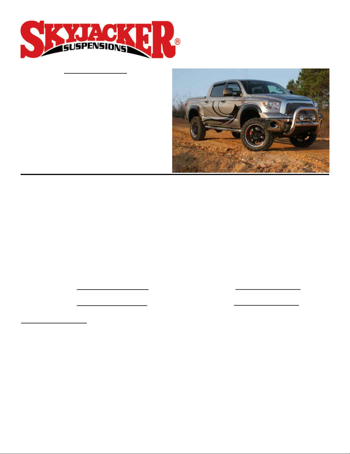
2007 - 2012 Toyota Tundra
6” Suspension Lift
Installation Instructions
www.skyjacker.com
REQUIRED TOOL LIST:
* Safety Glasses
* Metric / Standard Wrenches & Sockets
* Allen Wrenches
* Assorted Drill Bits
* Floor Jack
* Jack Stands
* Measuring Tape
* Torque Wrench
* Reciprocating Saw (4WD Models)
* Grinder (4WD Models)
* Welding Machine (4WD Models)
Before beginning the installation, thoroughly & completely read these instructions & the enclosed
driver’s WARNING NOTICE. Affix the WARNING decal in the passenger compartment in clear view
of all occupants. Refer to the Parts List to insure that all parts & hardware are received prior to the
disassembly of the vehicle. If any parts are found to be missing, contact SKYJACKER® Customer
Service at 318-388-0816 to obtain the needed items. If you have any questions or reservations
about installing this lift kit, contact SKYJACKER® Technical Assistance at 318-388-0816.
Make sure you park the vehicle on a level concrete or asphalt surface. Many times a vehicle is not
level (side-to-side) from the factory & is usually not noticed until a lift kit has been installed which
makes the difference more visible. Using a measuring tape, measure the front & rear (both sides)
from the ground up to the center of the fender opening above the axle. Record this information
below for future reference.
Driver Side Front: Passenger Side Front:
Driver Side Rear: Passenger Side Rear:
IMPORTANT NOTES:
• OEM wheels can not be reused in the installation of this suspension lift. 17" diameter or larger
wheels must be used to install this suspension lift.
• This lift is determined from the amount of lift to the front of the vehicle, while only lifting the rear to
a position level with the front.
• If larger tires (10% more than the stock diameter) are installed, speedometer recalibration will be
necessary. Contact your local Toyota dealer or an authorized dealer for details.
• After installation, a qualified alignment facility is required to align the vehicle to the OEM
specifications.
I-TU761 REV5 7-12 Pg 1
Page 2

Kit Box Breakdown:
TU761A:
ITEM# DESCRIPTION QTY
TU756STS Tundra Performance Strut 2
TU76L Tundra Driver Knuckle 1
TU76R Tundra Passenger Knuckle 1
TU76FCM-B Tundra Front Cross Member 1
TU76RCM-B Tundra Rear Cross Member 1
TU76BSB-D Tundra Driver Bump Stop Bracket 1
TU76BSB-P Tundra Passenger Bump Stop Bracket 1
TU76SBL Sway Bar Endlinks, Pair 1
TUCBL214 2.25” Carrier Bearing Lowering Spacers 1
SBL20 Sway Bar Lowering Brackets, Pair 1
HB-TU746-BLE Brakeline Extension Bracket Hardware Bag 1
HB-TU76-BS/DB Bump Stop / Differential Hardware Bag 1
HB-TU76C Rear Cross Member Caps, Pair 1
HB-TU76-CM Frontt & Rear Cross Member Hardware Bag 1
HB-TU76SSE Steering Stop Extensions, Pair 1
Hardware Bag Breakdown:
HB-TU746-BLE
ITEM# DESCRIPTION QTY
F460BLE-F Front Brake Line Ext Bracket 2
RBLE03-S Rear Brake Line Ext Bracket 1
RBLE10-S ABS Line Ext Bracket 1
RBLE60U-S E-brake Ext Bracket 2
VH1410 Vent Hose 1/4" X 10" 1
516X34CTBG5 5/16" X 3/4" Coarse Thread Bolt 6
516CTN 5/16"-18 Lock Nut 6
HB-TU76-BS/DB
ITEM# DESCRIPTION QTY
10x25MMB-1.25 10MM x 25MM - 1.25 TPI Bolt 4
10MMN-1.25 10MM - 1.25 TPI Lock Nut 4
38SAEW 3/8” SAE Washer 8
916x6FTB 9/16” x 6” Fine Thread Bolt 2
916x212FTB 9/16” x 2 1/2” Fine Thread Bolt 1
916FTN 9/16”- 18 Lock Nut 3
12USSW 1/2” USS Washer 2
916SAEW 9/16” SAE Washer 4
HB-TU76C
ITEM# DESCRIPTION QTY
TU76C-DS Driver Cross Member Cap 1
TU76C-PS Pass Cross Member Cap 1
Pg 2I-TU761
Page 3
HB-TU76-CM
ITEM# DESCRIPTION QTY
18x50MMB 18MM x 50MM- 2.5” TPI Bolt 4
18MMFW 5/8” - A325 Flat Washer 8
18MMN 18MM-2.5 TPI Lock Nut 4
24x50MMB 24MM x 50MM- 3.0 TPI Bolt 4
24MMFW 24MM Flat Zinc Washer 8
24MMN 24MM- 3.0 TPI Lock Nut 4
HB-TU76SSE
ITEM# DESCRIPTION QTY
TU76SSE-D Driver Steering Stop Plate 1
TU76SSE-P Pass Steering Stop Plate 1
Kit Box Breakdown:
TU761PR:
ITEM# DESCRIPTION QTY
916x212x12U 9/16” x 2 1/2” x 12” Square U-bolt 4
HB-916 8- 9/16” Lock Nut 1
RBF425 4.25” Flat Block 2
TU761PRS:
ITEM# DESCRIPTION QTY
916x212x734U 9/16” x 2 1/2” x 7 3/4” Square U-bolt 4
HB-916 8- 9/16” Lock Nut 1
Hardware Bag Breakdown:
HB-916
ITEM# DESCRIPTION QTY
916FTN 9/16-18 Lock Nut 8
I-TU761 Pg 3
Page 4
Front Installation:
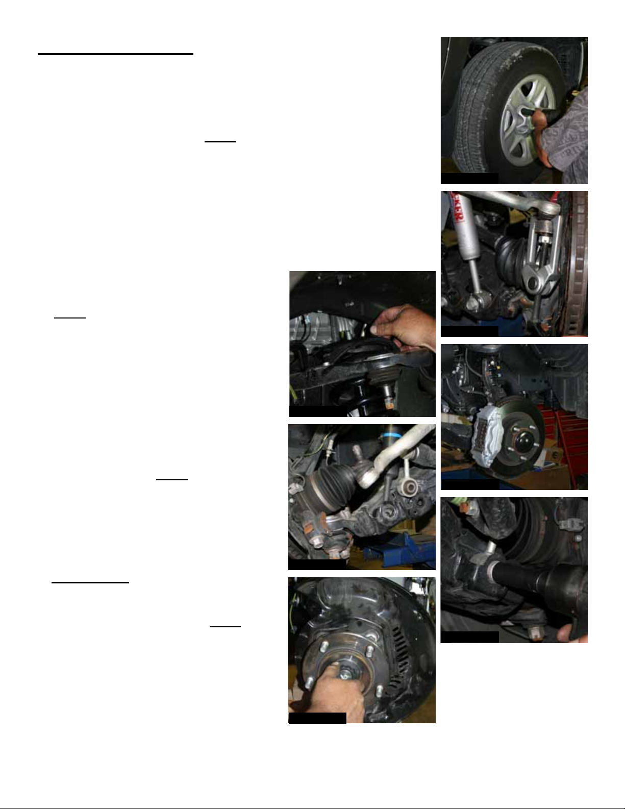
1. With the vehicle on flat level ground, set the emergency brake
& block the rear tires / wheels. Place a floor jack under the lower
control arm’s front cross member & raise the vehicle. Place jack
stands under the frame rails, behind the front wheel wells & lower the
frame onto the jack stands. Note: If the vehicle is equipped with a skid
plate, remove it at this time. This is in preparation for Step # 8.
2. Remove the front tires / wheels. (See Photo # 1)
3. Remove the tie rod end nut from the steering knuckle & remove the tie
rod end from the steering knuckle using a tie rod puller or similar tool.
(See Photo # 2)
4. Disconnect the brake caliper from the
brake rotor & disconnect the brake line
from the upper A-arm. (See Photo # 3)
Note: Simply wire the brake caliper out of
the way, it will not be necessary to
disconnect the brake line from the brake
caliper.
5. Disconnect the sway bar end links &
remove the sway bar. (See Photo # 4)
Disconnect the three upper strut retaining
nuts. (See Photo # 5)
6. Disconnect the upper A-arms from the
steering knuckles. Note: It may be
necessary to strike the side of the steering
knuckle with a dead blow hammer to
dislodge the upper ball joint. Be careful
not to damage the ball joint itself. (See
Photo # 6)
7. 4WD Models: Disconnect the CV-shafts.
(See Photo # 7)
8. Disconnect the lower A-arm. Note: Be
careful to place a jack under the A-arm for
support. Disconnect the lower strut mount
& remove.
Photo # 5
Photo # 6
Photo # 1
Photo # 2
Photo # 3
Photo # 4
Photo # 7
I-TU761 Pg 4
Page 5
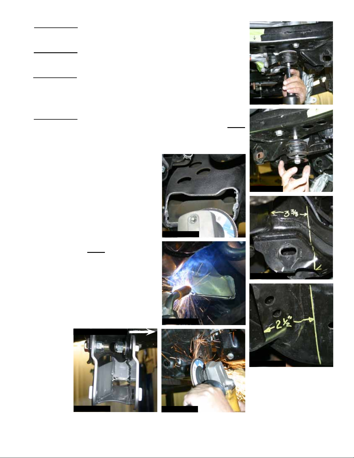
9. 4WD Models: Support the front differential with a transmission jack.
(See Photo # 8)
10. 4WD Models: Remove the differential mounting bolts & remove the
differential brackets. (See Photo # 9)
11. 4WD Models: It will be necessary to cut the rear cross member with
a reciprocating saw. The driver side will need to be cut for front
driveshaft clearance. The measurement is 3 3/8” from the inside of
the frame rail. (See Photo # 10)
12. 4WD Models: It will be necessary to cut the passenger side cross
member 2 1/2” from the lower A-arm mount. (See Photo # 11) Note:
It will be necessary to grind down this area after cutting for the new
Skyjacker cross member caps to be welded in place. (See Photos
# 12 & # 13)
13. The OEM alignment cam brackets
(alignment ears) will need to be ground
down for the installation of the new
Skyjacker cross members. This will have
to be done on the front side of both front
& rear lower A-arm mounts. (See Photo
# 14)
Photo # 8
Photo # 9
14. Install the new Skyjacker front cross
member using the supplied 24MM bolts,
washers, & nuts. Note: Do not tighten
the hardware completely at this time.
The cross member should be installed
with the bolt flanges on the front side of
the OEM cross member flanges. (See
Photo # 15)
Front of Vehicle
Photo # 12
Photo # 10
Photo # 13
Photo # 11
Photo # 15
I-TU761 Pg 5
Photo # 14
Page 6
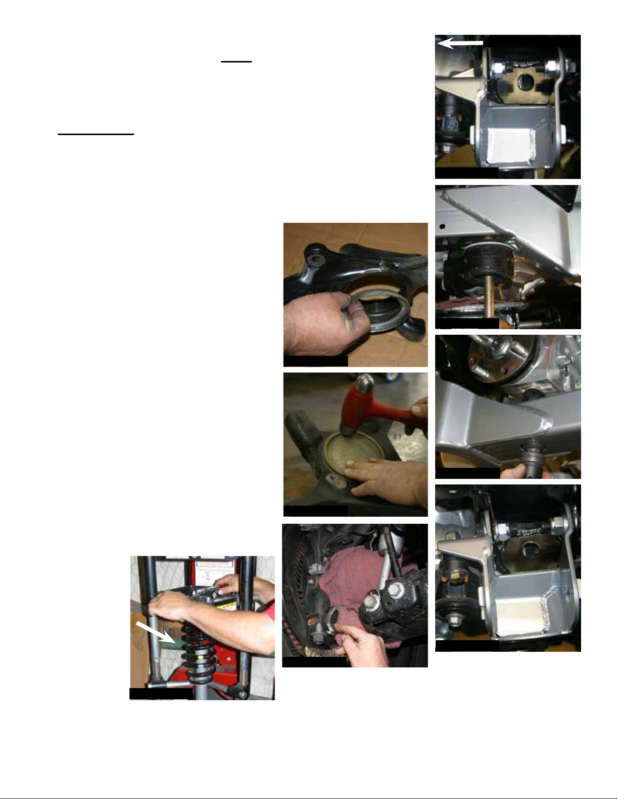
15. Install the new Skyjacker rear cross member using the supplied
18MM bolts, washers, & nuts. Note: Do not tighten the hardware
completely at this time. The cross member should be installed with
the bolt flanges on the front side of the OEM cross member flanges.
(See Photo # 16)
16. 4WD Models: Raise & safely support the front differential into place
using the supplied 9/16" x 6" bolts, washers, & nuts. Loosely bolt the
differential to the new front cross member. (See Photo # 17) Attach
the differential pinion support bracket, under the pinion, to the new
rear cross member using the OEM hardware & the supplied 9/16" x
2 1/2" bolt, washers, & nut. (See Photos # 18 & # 19) Install the new
Skyjacker differential vent hose & tighten all cross member &
differential hardware at this time.
17. Remove the hub bearing assembly from
the OEM knuckle & reinstall to the new
Skyjacker steering knuckle using the
OEM hardware. Make sure the OEM seal
(4WD Models) or OEM hub plug (2WD
Models) is reinstalled square in the new
Skyjacker steering knuckle. (See Photos
# 20 & # 21)
Photo # 20
Front of Vehicle
Photo # 16
Photo # 17
18. Weld in place the new Skyjacker steering
stop spacers. Match these new steering
stop spacers with the contour of the
OEM steering stops. Weld in place by
placing a weld across the top & bottom
of the supplied spacers. (See Photo
# 22)
19. Disassemble the OEM strut assembly
using a strut spring compressor. (See
Photo # 23)
Photo # 18
Photo # 21
Photo # 19
Photo # 22
Photo # 23
I-TU761 Pg 6
Page 7
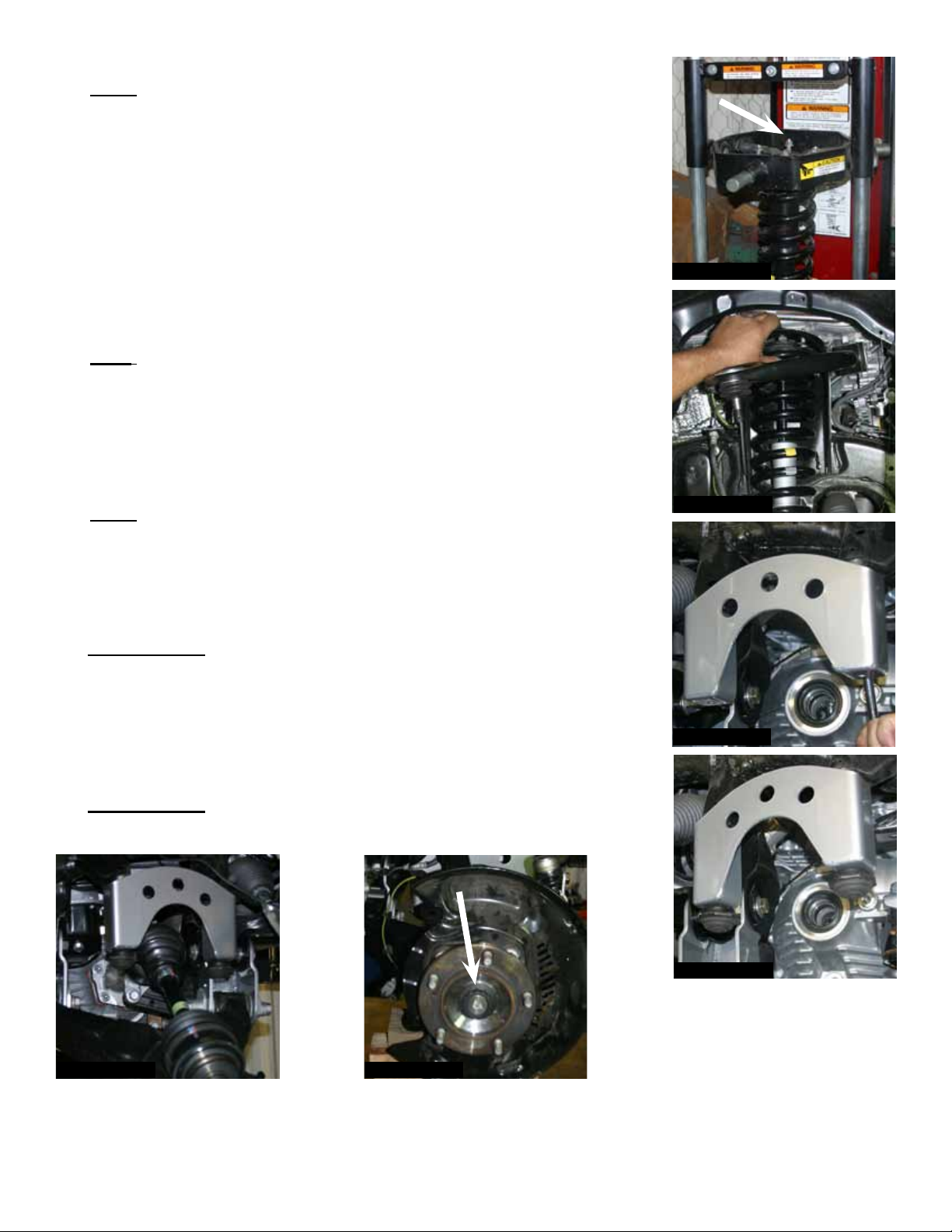
20. Install the OEM coil & top assembly to the new Skyjacker strut.
Note: There are four snap ring grooves located on the new Skyjacker
strut body. The ring is installed in the third groove from the bottom of
the strut when shipped. This will yield 6" of lift. The top upper groove
is only to be used when 6" of lift is desired, but aftermarket
accessories have been added that weigh the front end down, ie.
Winch, After Market Bumper, & etc. The lower ring grooves may be
used if you would like to keep the OEM rake. (Front of vehicle lower
than the rear). Once the coil spring seat retaining ring has been
placed, check all suspension components for any contact or
interference. If suspension component contact or interference is
present, lower the coil spring seat by lowering the coil spring
seat retaining ring until no contact or interference is present.
Note: Skyjacker provides a new upper strut retaining nut for the new
replacement strut. (See Photo # 24) Install the new Skyjacker strut
using the OEM upper hardware. (See Photo # 25)
21. Install the new Skyjacker bump stop brackets using the supplied
10mm x 25mm bolts. (See Photo # 26) Attach the OEM bump stops
to the new bump stop brackets using the supplied 10mm nuts.
Note: The bump stop brackets are side specific for passenger &
driver side. (See Photo # 27)
Photo # 24
Photo # 25
22. Reinstall the lower A-arms to both the driver & passenger sides.
Reinstall the lower strut mount to the lower A-arm.
23. 4WD Models: Install the CV axles. (See Photo # 28) Attach the new
Skyjacker steering knuckle to the upper & lower A-arm using the
OEM hardware.
24. Attach the OEM ABS line to the upper A-arm & relocate the ABS line
to the new Skyjacker steering knuckle.
25. 4WD Models: Attach the CV axle to the new Skyjacker steering
knuckle. (See Photo # 29)
Photo # 26
Photo # 27
Photo # 28
I-TU761 Pg 7
Photo #29
Page 8
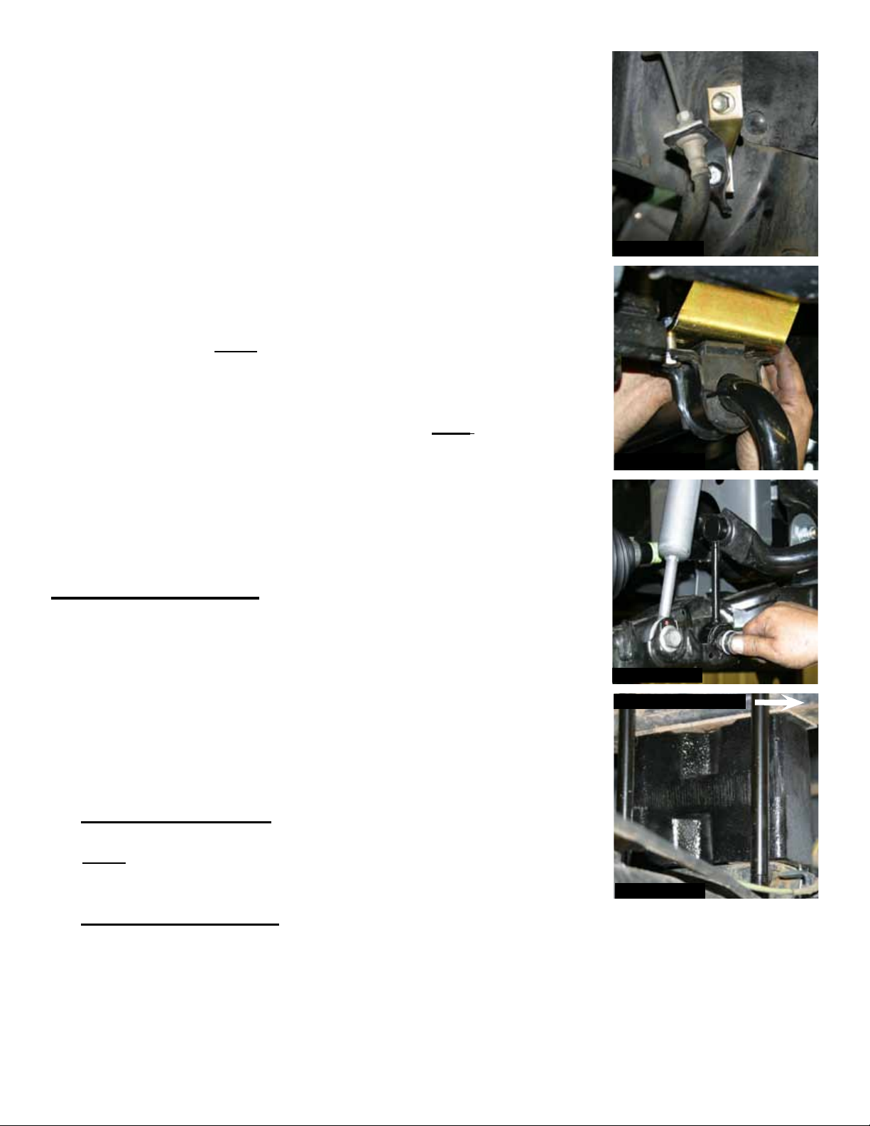
26. Install the new Skyjacker front brake line extension brackets using
the OEM hardware & the supplied 5/16" x 3/4" bolts & nuts. (See
Photo # 30)
27. To install the tie rod end to the new Skyjacker steering knuckle the tie
rods will need to be swapped from driver to passenger & passenger
to driver side. Attach the outer tie rod to the new Skyjacker steering
knuckles using the OEM hardware. Reinstall the brake rotors, brake
calipers, & etc.
28. Reinstall the sway bar using the new Skyjacker drop brackets. The
new sway bar brackets will install between the sway bar & the OEM
mount on the frame using the OEM hardware. The sway bar will be
attached to the new brackets using the supplied 7/16" x1 1/2” bolts,
washers, & nuts. Note: The brackets should offset the sway bar
towards the front of the vehicle. (See Photo # 31)
29. Install the new Skyjacker sway bar end links. Be sure to install the
end link with the pivoting end at the sway bar. Note: The sway bar
end links are side specific. (See Photo # 32)
30. Install the front tires / wheels & lower the front of the vehicle to the
ground.
Rear Installation:
1. With the vehicle on flat level ground, block the front tires / wheels.
Raise the rear of the vehicle & properly support using jack stands.
Remove the rear tires / wheels.
Photo # 30
Photo # 31
Photo # 32
2. Disconnect the E-brake cables, ABS line, & rear brake lines from the
differential.
3. Support the rear differential & remove the rear shocks & u-bolts.
4. Rear Block Installation:
Install the new Skyjacker rear blocks & new Skyjacker u-bolts.
Note: Install the new rear blocks with the female hole of the new rear
block offset towards the front of the vehicle. (See Photo # 33)
5. Rear Spring Installation:
Install the new Skyjacker rear leaf springs using the OEM hardware.
I-TU761 Pg 8
Front of Vehicle
Photo # 33
Page 9
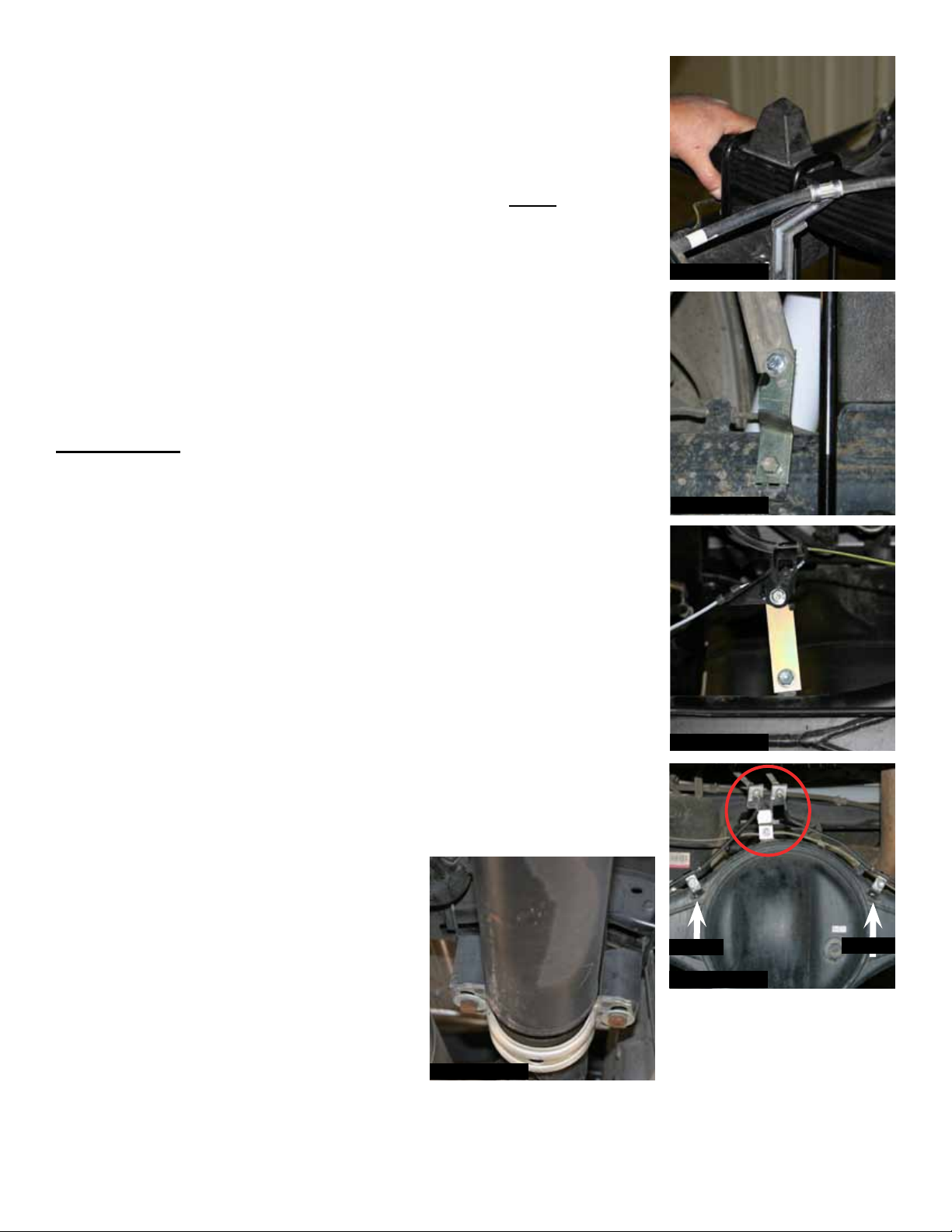
6. Install the new Skyjacker u-bolts. (See Photo # 34)
7. Install the new Skyjacker rear shocks using the OEM hardware.
8. Install the new Skyjacker E-brake cable brackets, ABS line bracket, &
rear brake line bracket to the differential using the supplied 5/16" x
3/4" bolts & nuts. (See Photos # 35, # 36, & # 37) Note: The OEM
rear brake line cable clamps must be inverted to raise the OEM
brake line up from the differential. (See Photo # 37)
9. Models equipped with an OEM carrier bearing will need to install the
new Skyjacker carrier bearing lowering spacers using the supplied
10mm x 80mm bolts & washers. (See Photo # 38)
10. Install the rear tires / wheels & lower the rear of the vehicle to the
ground.
FINAL NOTES:
• After the installation is complete, double check that all nuts & bolts are
tight. Refer to the following chart for the proper torque specifications.
(Do not retighten the nuts & bolts where thread lock compound was
used.)
• With the vehicle on the ground, cycle the steering lock to lock &
inspect the steering, suspension, brake lines, front & rear drivelines,
fuel lines, & wiring harnesses for proper operation, tightness, &
adequate clearance.
• H a v e t h e h e a d l i g h t s r e a d j u s t e d t o t h e p r o p e r s e t t i n g s .
• Have a qualified alignment center realign the vehicle to the OEM
specifications.
• Retorque all the bolts after the first 100 miles.
Photo # 34
Photo # 35
Photo # 36
Invert
Photo # 37
Photo # 38
I-TU761 Pg 9
Invert
Page 10
TORQUE SPECIFICATIONS
INCH SYSTEM
Bolt Size Grade 5 Grade 8
5/16 15 FT LB 20 FT LB
3/8 30 FT LB 35 FT LB
7/16 45 FT LB 60 FT LB
1/2 65 FT LB 90 FT LB
9/16 95 FT LB 130 FTLB
5/8 135 FT LB 175 FT LB
3/4 185 FT LB 280 FT LB
• The above specifications are not to be used when the bolt is being installed with a bushing.
Bolt Size Class 8.8 Class 10.9
6MM 5 FT LB 9 FT LB
8MM 18 FT LB 23 FT LB
10MM 32 FT LB 45 FT LB
12 MM 55 FT LB 75 FT LB
14MM 85 FT LB 120 FT LB
16MM 130 FT LB 165 FT LB
18MM 170 FT LB 240 FT LB
METRIC SYSTEM
Seat Belts Save Lives, Please Wear Your Seat Belt.
I-TU761 Pg 10
 Loading...