

Page 1
Before beginning the installation, read these instructions and the enclosed driver’s WARNING
NOTICE thoroughly and completely. Also affix the WARNING decal in passenger compartment in
clear view of all occupants. If any of these items are missing from this instruction packet, do not proceed with installation, but call SKYJACKER®to obtain needed items. If you have any questions or
reservations about installing this lift kit, call SKYJACKER®at 318-388-0816 for Technical Assistance
or Customer Service departments.
Make sure you park the vehicle on a level concrete or asphalt surface. Many times a vehicle is
uneven (side-to-side) from the factory, but usually not noticed until a lift kit has been installed which
makes the difference more visible. Using a measuring tape, measure the front and rear (both sides)
from the ground up to the center of the fender opening above the axle. Record below for future reference.
IMPORTANT NOTES:
• Please refer to Parts List to insure that all parts and hardware are received prior to disassembly of
vehicle. If any parts are found to be missing, contact your dealer as soon as possible.
• If larger tires (10% more than stock diameter) are installed, speedometer recalibration is necessary
(see Toyota dealer or Tire Store).
• After installation, a qualified alignment facility is required to align the vehicle to factory specs.
Kit Box Breakdown:
TU720MS: Main Component Box
ITEM# DESCRIPTION QTY
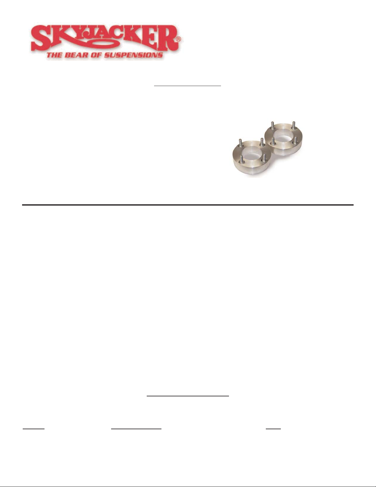
TU720MS-S 07 TUNDRA 2" ALUM FRONT SPACER 2
10X10MMSE 10X10MM STUD EXTENSION 8
LT100 LOCTITE 1 ML TUBE 1
2007 Toyota Tundra
2” Leveling Kit
Installation Instructions
Part # TU720MS
REQUIRED TOOL LIST:
• Metric/Standard Wrenches & Sockets
• Floor Jack
• Jack Stands
• Measuring Tape
• Torque Wrench
www.skyjacker.com
I-TU720MS Pg 1
Page 2
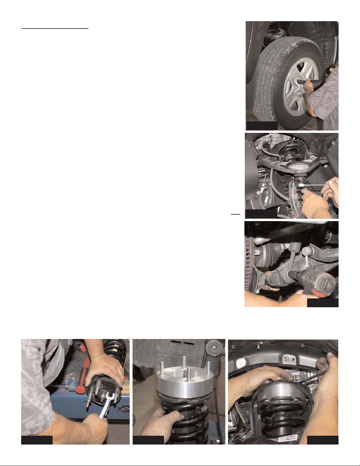
Photo #2
I-TU720MS Pg 3
Photo #3
Photo #6Photo #4 Photo #5
Photo #1
Front Installation:
1. Secure and properly block the tires of vehicle on a level concrete or
asphalt surface.
2. Raise the vehicle from the front center cross member and remove
tires and wheels. (See Photo #1)
3. Disconnect outer tie rod from steering knuckle. Disconnect the
Upper A-Arm ball joint from the top of the steering knuckle. (See
Photo #2)
5. Disconnect Strut from upper tower mount. Disconnect the lower
strut mounting bolts from the lower A-Arm. Disconnect sway bar
end link. (See Photo #3). Remove Struts from vehicle.
6. With Struts removed, apply thread locking compound to the
threads. Install and tighten the supplied stud extensions. (See
Photo #4)
7. Install aluminum spacer on to the top of the factory strut. (See
Photo #5). Install strut assembly. Attach to the factory upper tower
mount using the factory fasteners. (See Photo #6)
8. Re-Attach lower strut mount @ A-Arm, upper ball joint, outer tie rod
end and sway bar link. Re-Install tires and wheels.
FINAL NOTES:
* After installation is complete, double check that all nuts and bolts are tight. Do Not
re-tighten nuts/bolts where thread locking compound was applied.
* Check to ensure there is adequate clearance between All rotating, mobile and
fixed members. Check clearance between inner side wall of tires.
* Ensure there is adequate clearance between exhaust and brake lines, fuel lines,
fuel tank, floor board, and wiring harnesses. Check steering gear for interference
and proper working order. Inspect brake lines for damage and adequate clearance. Test brake system.
* With the vehicle on the floor, cycle steering lock to lock and inspect steering, sus-
pension, drive line and brake line systems for proper operation, tightness and
adequate clearance.
* Have headlights readjusted to proper settings.
* Front end realignment is necessary so have a qualified alignment center
realign front end to factory specifications.
 Loading...