

Page 1
Toyota 4x4 IFS
86-95 Pickup, 86-89 4 Runner
4” Lift Kit
www.skyjacker.com
REQUIRED TOOL LIST:
* Metric / Standard Wrenches and Sockets
* Floor Jack
* Jack Stands
* Measuring Tape
* Torque Wrench
1. Before beginning the installation, read these instructions and the enclosed driver’s
WARNING NOTICE thoroughly and completely. Also affix the WARNING decal in passenger compartment in clear view of all occupants. If any of these items are missing from this instruction packet,
do not proceed with installation, but call SKYJACKER® to obtain needed items. If you have any
questions or reservations about installing this lift kit, call SKYJACKER® at 318-388-0816 for
Technical Assistance or Customer Service departments.
Make sure you park the vehicle on a level concrete or asphalt surface. Many times a vehicle is
uneven (side-to-side) from the factory, but usually not noticed until a lift kit has been installed which
makes the difference more visible. Using a measuring tape, measure the front and rear (both sides)
from the ground up to the center of the fender opening above the axle. Record below for future reference.
Installation Instructions
Driver Side Front: Passenger Side Front:
Driver Side Rear: Passenger Side Rear:
IMPORTANT NOTES:
• Please refer to Parts List to insure that all parts and hardware are received prior to disassembly of
vehicle. If any parts are found to be missing, contact your dealer as soon as possible.
• If larger tires (10% more than stock diameter) are installed, speedometer recalibration is necessary
(see Toyota dealer or Tire Store).
• Only wheels with no more than 3 3/4” backspacing can be used with this lift.
• After installation occurs, a qualified alignment facility is required to align the vehicle to factory
specs.
• After installation occurs, realign headlights to proper position.
IT422/432 REV1 4-10 Pg 1
Page 2

Kit Box Breakdown:
T422:
ITEM# DESCRIPTION QTY
T4SP-B TOY 4" SKID PLATE BRACKET 1
401-L TOY 4" SPINDLE - LEFT 1
401-R TOY 4" SPINDLE - RIGHT 1
T4FCM-B TOY 4" FRONT A-ARM CROSS MEMBER 1
T4RCM-B TOY 4"REAR A-ARM CROSS MEMBER 1
T4DDB-B TOY 4" DRIVER DIFF DROP BRKT 1
T4CDB-B TOY 4" CENTER DIFF DROP BRACKET 1
T4PDB-B TOY 4" PASS DIFF DROP BRACKET 1
T4BP-B TOY 4" BUMP STOP SPACER BRACKET 4
T4SBL-L TOY 4" SWAY BAR LWR BRKT-LEFT 1
T4SBL-R TOY 4" SWAY BAR LWR BRKT-RIGHT 1
BK-T421 BRAKE LINE HARDWARE 1
HB-T421 KIT HARDWARE BAG 1
Hardware Bag Breakdown:
BK-T421 Brakeline Hardware
ITEM# DESCRIPTION QTY
TFBE-2 TOYOTA FRONT BRAKE LINE EXTENSION 2
TRBE-1 TOYOTA REAR BRAKE LINE EXTENSION 1
T4RPV-B TOY 4"REAR PROP.VALVE BRACKET 1
38X1FTB 3/8 X 1 FINE THREAD BOLT 3
516X1FTB 5/16 X 1 FINE THRD BOLT 2
38FTN 3/8-24 FINE N/I LOCK NUT 3
516FTN 51/6-24 FINE N/I LOCK NUT 2
38SAEW 3/8 SAE WASHER 3
516SAEW 5/16 SAE WASHER 2
Pg 2IT422/432
Page 3

Hardware Bag Breakdown:
HB-T421 Lift Hardware
ITEM# DESCRIPTION QTY
38X2FTB 3/8 X 2 FINE THREAD BOLT, GR8 4
516X1FTB 5/16 X 1 FINE THREAD BOLT 6
12X112FTB 1/2 X 1 1/2 FINE THREAD BOLT 3
12X214FTB 1/2 X 2 1/4 FINE THREAD BOLT 1
12X212FTB 1/2 X 2 1/2 FINE THREAD BOLT 1
58X212FTB 5/8 X 2 1/2 FINE THREAD BOLT 2
58X412FTB 5/8 X 4 1/2 FINE THREAD BOLT 4
38FTN 3/8-24 FINE N/I LOCK NUT 4
516FTN 51/6-24 FINE N/I LOCK NUT 6
12FTN 1/2-20 FINE N/I LOCK NUT 5
58FSFTN 5/8-18 FLANGE STOVER NUT 2
58FTN 5/8-18 NYLON INSERT LOCKNUT 4
38SAEW 3/8 SAE WASHER 11
516SAEW 5/16 SAE WASHER 14
12SAEW 1/2 SAE WASHER 6
TS250 TOY SLEEVE,IFS .250" LONG 1
TS875 TOY SLEEVE,IFS .875" LONG 1
TS1125 TOY SLEEVE,IFS 1.125" LONG 1
TTS34 TOYOTA TAPERED SLEEVE, 3/4" 2
T4LSP TOY 4" LOCATING SPACER 8
BPBN BUMP STOPS, BUTTON SHAPE 4
LT100 THREAD LOCK COMPOUND 1
Kit Box Breakdown:
T421R:
ITEM# DESCRIPTION QTY
RB35 3.5" REAR BLOCK 2
916X212X1012 1 U-BOLT WITH NUTS 4
Note: T421RS will not consist of lift blocks and the rear U-Bolts will be part # 916x212x7
T431R:
ITEM# DESCRIPTION QTY
RB35 3.5" REAR BLOCK 2
916X318X912 1 U-BOLT WITH NUTS 4
Note: T431RS will not consist of lift blocks and the rear U-Bolts will be part # 916x318x812
IT422/432 Pg 3
Page 4
FRONT :
2. Place floor jack under front axle and raise vehicle. Place jack
stands under frame to support vehicle. Set emergency brake and
block rear wheels, in front and behind tires. Remove front tires
and wheels.
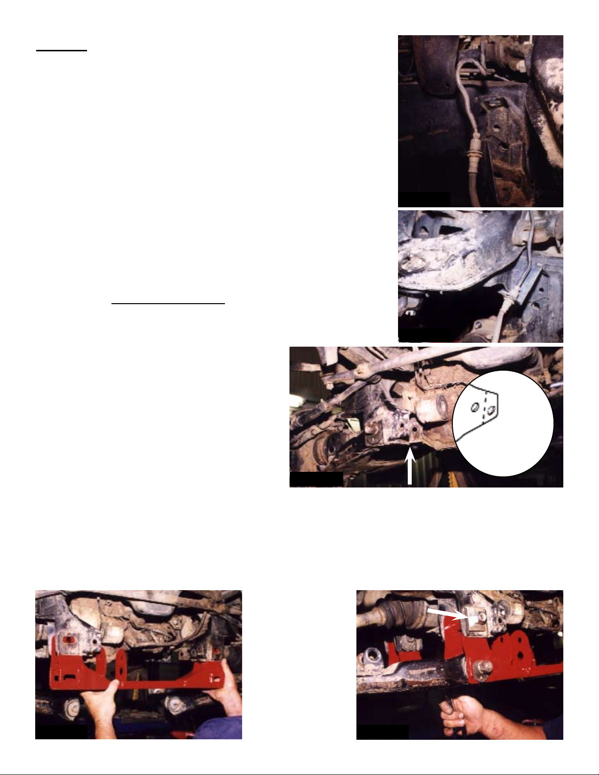
3. Remove clip from front brakeline and bracket. Cut a slot in original
brake line bracket (to center of hole) and remove brakeline out of
bracket. Install new brakeline drop bracket to OEM bracket and
put 3/8” flat washer on top. Insert 3/8 x 1” bolts and washers
through both brackets and tighten with 3/8” lock nuts on bottom.
You may need to reform line slightly. Be sure not to kink or cause
any interference of line. Reinstall OEM brakeline clip to hose at
bracket. See Photo #1 and #2. Note: Extended DOT approved
stainless steel brakelines are available from Skyjacker. (Part #
FBL30)
4. Remove shocks and sway bar plus bump stops on each side (4
bump stops total). Remove eccentric adjustment bolt nuts from
front and rear. Remove front cross member from mounting
bracket. On passenger side only, cut off both existing mounting
tabs between the two bolt holes for differential clearance. See
Arrow in Photo #3. (Shown after tabs have been cut away).
5. Remove eccentric bolts (front and rear) from
the original front lower A-Arms.
6. Install the new front A-Arm drop
crossmember assembly into the OEM
brackets (See Photo #4). Use new 5/8” x 4
1/2” hex bolts and 5/8” lock nuts, placing the
1 7/8” x 2” locating spacers on the outsides
(see arrow in Photo #5) ; torque to 150 ft. lbs.
Reinstall OEM eccentric bolts, OEM Cam
washers, and nuts at bottom; torque to 103 ft.
lbs.
Photo #3
Photo #1
Photo #2
Cut Tab Here
Existing OEM
Bracket
Photo #4 Photo #5
IT422/432 Pg 4
Page 5
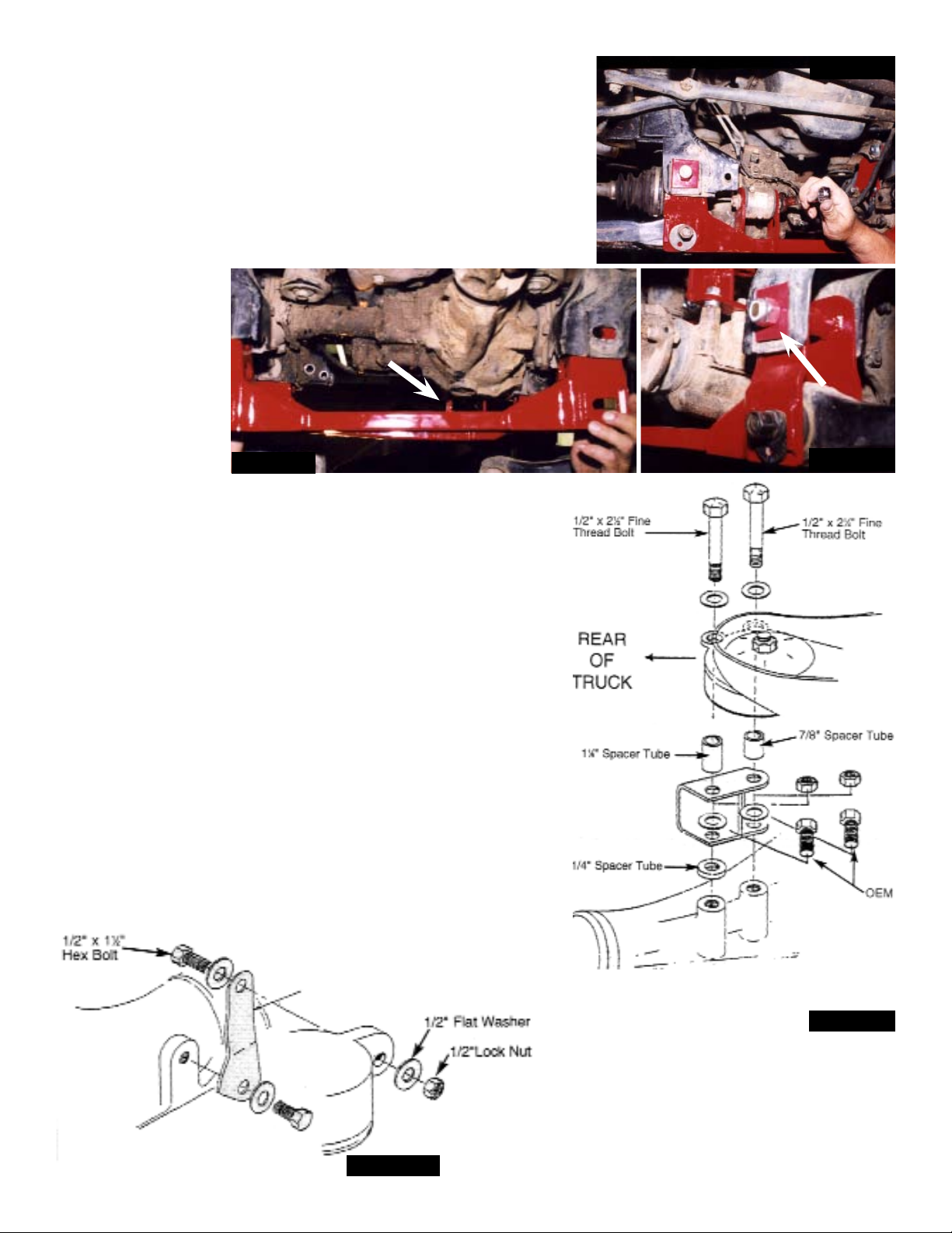
7. Using original bolt and nut, install front differential to new front
cross member and tighten. (See Photo #6)
8. Install new rear A-Arm drop crossmember assembly into OEM
brackets. (See Photo #7). Use new 5/8” x 4 1/2” hex bolts
and 5/8” lock nuts, placing the 1 7/8” x 2” locating spacers on
the outsides (See arrow in Photo #8); torque to 150 Ft. Lbs.
Reinstall OEM eccentric bolts with hole in OEM Cam washer
at bottom; torque to 103 Ft. Lbs. Note: under differential
insert a 3/8” x 2” bolt and washer through hole in new rear
cross member
assembly ( See
Arrow in Photo
#8). Do not install
nut at this time;
there will be
room to install
later.
9. Lower differential
being careful not
to pull out front
driveshaft. Install new center differential as shown in Photo
#9. (A) Install the 1/4” spacer tube at rear lower mounting
between differential and bracket. Install existing OEM bolts
through bracket, spacer and into the two bottom holes
(use loctite), and torque to 70 Ft. Lbs. (B) Install 1 1/8”
spacer tube at rear of upper OEM rubber mount with 1/2”
x 2 1/2” hex bolt, 1/2” flat washer and lock nut. (C) Install
7/8” spacer tube at rear of upper OEM rubber mount with
1/2” x 2 1/4” bolt, 1/2” flat washer and 1/2” lock nut. Torque
1/2” bolts to 85 Ft. Lbs.
10. Install passenger side differential drop bracket using 1/2”
x 1 1/2” hex bolt with two 1/2” flat washers and lock nut
into upper hole of OEM rubber mount. Install bottom using
original bolt and washer (wide part of bracket should be at
bottom with hole towards front). Apply loctite and tighten to
70 Ft. Lbs. (See Photo #10).
Photo #7
Photo #6
Photo #8
Photo #9
Photo #10
IT422/432 Pg 5
Page 6
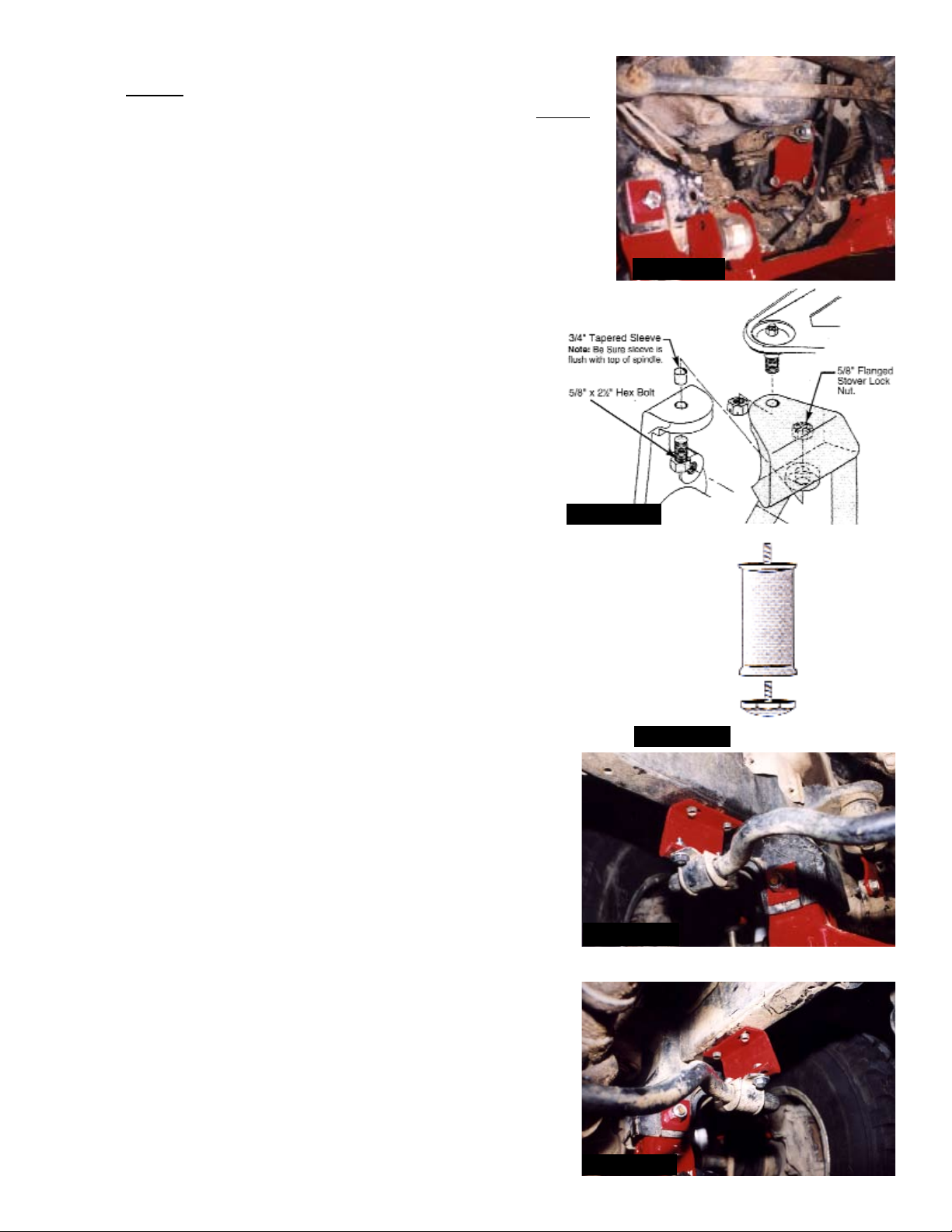
11. Install driver side differential drop bracket using OEM bolts in
two bottom holes. Apply loctite and torque to 70 Ft. Lbs. Use
1/2” x 1 1/2” hex bolts, washers, and lock nuts in two upper
holes. Torque to 85 Ft. Lbs. (See Photo #11).
12. Remove tie rods from steering knuckles. Remove two bolts on
back side (inside) of spindle which hold the metal bracket for
the brake hose.
13. Support lower A-Arms with floor jack and separate upper ball
joint from spindle. Using file, file corners off OEM spindle to
contour with bottom of new spindle adapter so that the bottom
of the new spindle seat surface is in contour with OEM
spindle top surface. Clean out hole on top of steering
knuckle (spindle).
14. As shown in Photo #12, insert tapered spindle sleeves
with small end downward. Be sure tapered sleeves are
flush with top of spindle (if necessary tap with a hammer,
or file down to be flush). Place new spindle adapters
onto original spindles, and install 5/8” x 2 1/2” hex bolts
and 5/8” flanged stover lock nuts. Note: Be sure to use
the special black Grade 8 Flanged Stover Lock Nut
supplied! Torque to 150 Ft. Lbs. Insert upper ball joints
into new spindle adapters and torque to 105 Ft. Lbs.
Reinstall tie rods, and torque to 67 Ft. Lbs. Next reinstall brake
hose brackets to bottom of new spindle adapters using OEM
bolts (apply loctite). Be sure to install cotter pins.
15. Slightly file original bump stop mounting lips on each side (only
the front two) for shock clearance. Install new Skyjacker shocks.
16. Attach new polyurethane bump bump stops to new bump stop
spacers. Then install bump stop spacers to original mounts with
3/8” coarse thread lock nuts. See Photo #13.
17. Install the two new sway bar drop down brackets to frame using
OEM hardware, but adding a 5/16” flat washer under bolt
heads. Install sway bar to bottom of new drop down brackets using new 5/16” x 1” bolts, 5/16” flat washers ( 1 under
bolt heads and 1 under nuts) and 5/16” lock nuts. Torque
all bolts to 25 Ft. Lbs. See Photo’s #14 and #15 (open
side goes inward with slant down and toward the front).
Tighten A-Arm end of sway bar.
Photo #12
Photo #11
Photo #13
Photo #14
Photo #15
IT422/432 Pg 6
Page 7
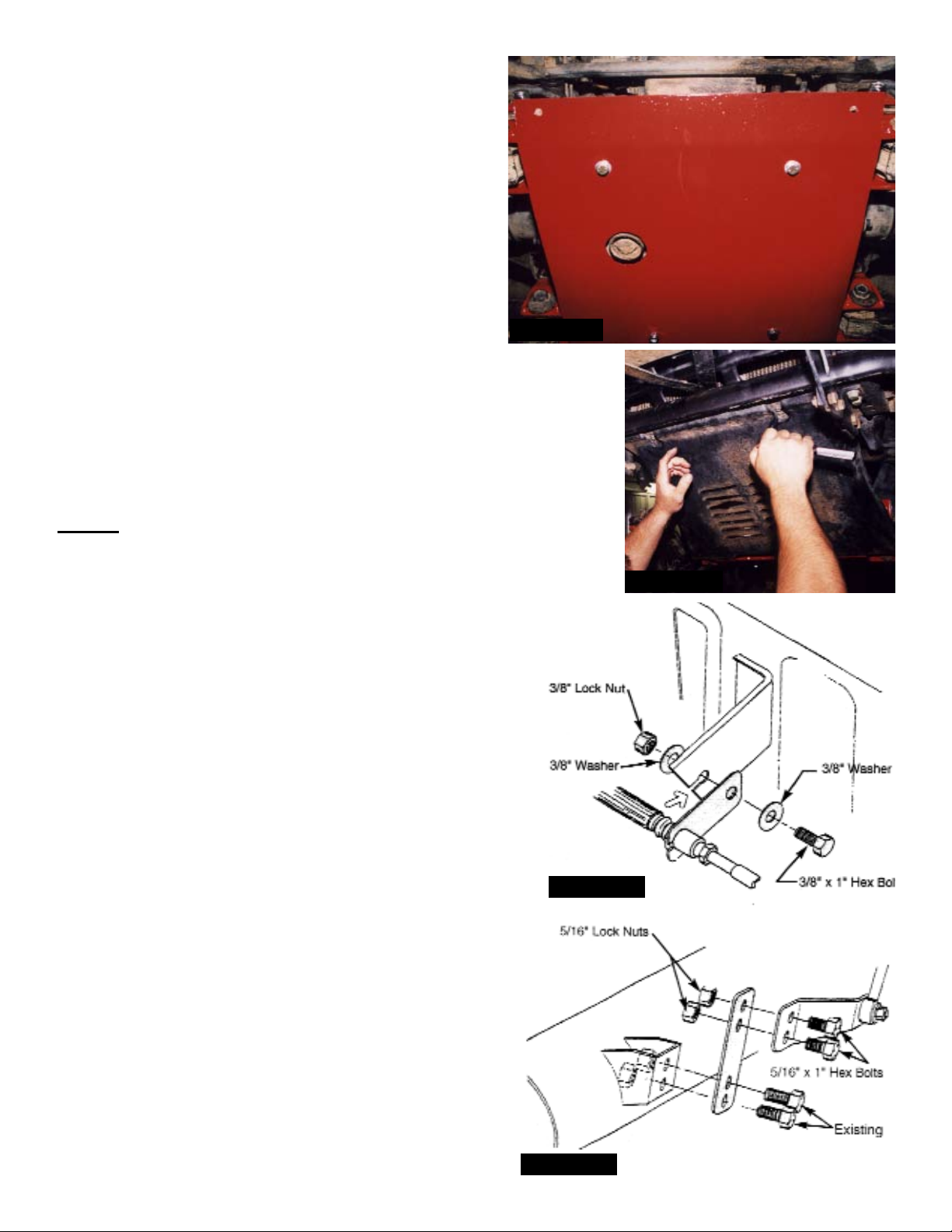
18. Install new lower skid plate to both new front and
rear A-Arms crossmember assemblies using 3/8”
x 2” bolts, 3/8” washers (one under each bolt
head, and 1 under each nut), and 3/8” lock nuts.
Install as shown with bolt head underneath skid
plate, except on the rear at passenger side, bolt
was installed in step #8 from top of cross
member down through the skid plate (install
washer and nut underneath skid plate). Torque
bolts to 37 Ft. Lbs. (See Photo #16).
19. If equipped with original front skid plate, reattach
it to front frame mounts using original hardware.
Attach bottom of OEM skid plate to front holes in
new lower skid plate using 5/16” x 1” bolts with
5/16” washers (1 under each bolt head, and 1 under each nut).
and 5/16” lock nuts. Tighten upper frame bolts. Next tighten
bottom bolts, being careful not to crush OEM mounting tabs.
See Photo #17
20. Install the front tires and lower vehicle to ground.
Photo #16
REAR:
21. Place floor jack under rear axle and raise vehicle. Place jack
stands under frame to support vehicle. Set emergency brake
and block front wheels, in front and behind tires. Remove
wheels and shocks.
22. Cut OEM bracket to center of hole to remove
brakeline/clip from bracket (See arrow in Photo #18).
Attach rear brake line drop down bracket to existing
bracket using 3/8” x 1” hex bolt, 3/8” flat washers and
3/8” lock nut. Torque to 37 Ft. Lbs. Install brake line
into lower bracket hole and reinstall OEM brake line
clip. Note: Extended DOT approved braided
stainless steel hoses are available from Skyjacker.
(Part #RBL30)
23. Unbolt brake equalizer arm bracket from axle. Install
new rear brake cable extension bracket to original axle
mount with OEM hardware. Mount equalizer bracket to
top of new extension bracket using 5/16” x 1” hex
bolts with locknuts. Torque to 20 Ft. Lbs. (See
Photo #19)
24. Loosen emergency brake cables by removing
cotter pin, pulling pin out from back side of brake
backing plate at adjuster.
25. Remove the axle U-Bolts and lower axle down a
few inches. Care should be taken because when
U-Bolts are removed, axle can move freely.
Photo #18
Photo #17
Photo #19
IT422/432 Pg 7
Page 8
If installing a Softride “System” w/ new Rear Springs, Skip To Step # 28.
26. Block Installation: Place the rear lift blocks in position on the axle making sure the pin in the
block is in the hole of the axle housing. Note: The short end of the block goes toward the front of
the vehicle so that the pinion will be rolled upward toward transfer case.
27. Raise the axle housing up until the pins in the spring aligns and seats in the holes in the blocks.
28. New Spring Installation: Remove the spring eye bolts and remove original springs from
vehicle. Install the new SOFTRIDE springs into original mounts.
29. Raise the axle housing up until the pins in the spring aligns and seats into the mounting pad on
the axle. Reinstall emergency brake cable, keeping cable under spring.
30. Re-mount the axle to the springs using the existing spring plates and the new U-Bolts using the
nylon lock nuts. Torque U-Bolts to only 85-90 Ft. Lbs.
31. Install new rear Skyjacker Shocks, and tires then lower vehicle to the ground.
Notes:
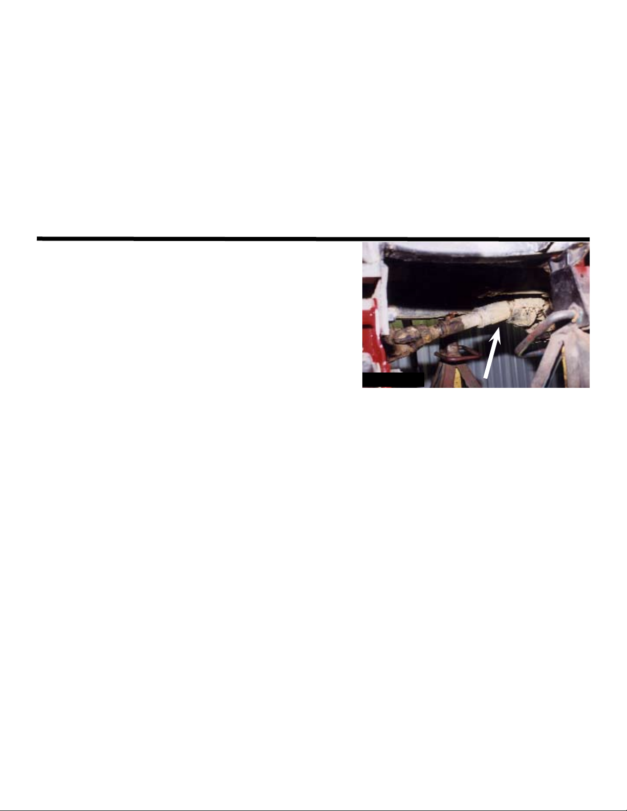
* Check front drive shaft at lower half of clamshell to
assure proper clearance, and grind if necessary. (See
Arrow in Photo #20).
* After installation is completed, double check that all nuts
and bolts are tight. (Do not retighten nuts where loctite
was used).
* After driving the first 50 miles, retorque all nuts and
especially bolts, torque again after another 100 miles
and periodically thereafter.
* Measure from center of Eccentric adjuster bolt to the
ground to ensure proper ride height.
* During alignment, the inner and outer tie rod ends on each side may need to be pulled out of
adjusting sleeve and cut 1/2” off tie rod ends so proper adjustment can be achieved.
* When installing larger tires and wheels, check for clearance of upper A-Arm.
Photo #20
Torques Specifications:
A-Arm Drop Bracket Bolts........................ ...100’ Lbs.
Crossmember Bolts.......................................45’ Lbs.
Eccentric Bolts.............................................103’ Lbs.
Inner Differential Bolts...................................70’ Lbs.
Passenger Differential Bolts..........................70’ Lbs.
Driver Differential Bolts..................................70’ Lbs.
Tapered Spindle Sleeve Bolt....................... 100’ Lbs.
Spindle to Upper Ball Joint..........................105’ Lbs.
Tie Rod Ends.................................................67’ Lbs.
U-Bolts.......................................................85-90’ Lbs.
Seat Belts Save Lives, Please Wear Your Seat Belt.
IT422/432 Pg 8
 Loading...