

Page 1
INSTALLATION INSTRUCTIONS
FOR
Adjustable Drag Link #SDL250
Drop Pitman Arm #FA325
Drop Pitman Arm #SA40
Application Information
Year V ehicle Model Lif t Required Product
77 1/2-79 F250 4WD Low Boy 2-3 FA325 Pitman A r m
3-4 SDL250 Drag Link
5-7 Both - F A325 Pitman Arm and SDL250 Drag Link
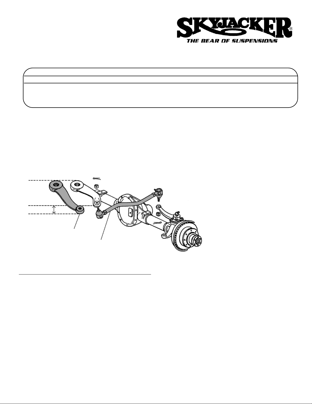
Read these instructions thoroughly and completely before beginning the inst allation. Refer to the dia gram below to aid ln the removal and inst all tion of these product s. If you are unsure of which product is
needed or recommended for your vehicle or you have any questions, call out technical assist ance line
at 318-388-0816.
The amount of lif t st ated above is measured at the center of the front axle.
NOTE: This diagram is shown
for models equipped with Dana
60 front axles. On Dana 44
axles, the #SDL250 drag link
inst alls from the bottom of
steering arm on axle housing
instead of the top as shown in
the diagram at lef t.
SDL250 Drag Link
FA325 Pitman A r m
2 Additional
Drop
Instructions for SDL250 Adjustable Drag Link
1. Place a jack under lef t front (driver s side) of vehicle, and jack up until tire is clear of the ground. Place jack st a nd
under axle supporting it securely, and remove lef t front tire.
2.Starting at the pitman arm end of the drag link, remove cotter pin and loosen the nut (Do Not remove nut at this
time). Now on the steering arm end of drag link, follow the same procedure.
3. If you have a pickle fork tool proceed to remove drag link and skip to step 6. Else continue through steps 4 and 5.
4. Using a ball pein hammer, strike the side of the pitman arm on the end by the drag link until drag link drops down. (If
you have a second hammer, you may find it help ful to hold it on the opposite side of the pitman arm serving as a
back up.)
Page 2
5. Move to the other end of drag link at the steering arm. Using the ball pein hammer, strike the side of steering arm on
the end by the drag link until drag link loosens up. At this time, remove the nut from each end of the drag link. (Note: if
also purchased the new pitman arm, follow the inst allation instructions below for p art #F A325 at this time.)
6. Inst all the drag link in the end of pitman arm and steering arm. Put new nut onto the drag link and
tighten, but Do Not insert cotter pin yet.
7. Inst all the tire, jack up vehicle enough to remove jack st and, remove jack stand and lower vehicle
to ground. Get inside vehicle and be sure steering wheel cross bars are aligned properly (as if
driving straight forward). If not, loosen the jam nut s on the drag link and adjust until steering is
centered.
NOTE: Be sure that there is NOT more than 3 to 6 threads visible past the jam nut.
8. T ighten all nut s securely (tie rod end nut s and jam nut s), and inst all the new cotter pins into tie
rod end studs. Do not forget to grease tie rod ends.
9. Recheck all nut s and inst allation af ter driving approximately 50 miles, again af ter the next 100
miles. Continue to check the drag link periodically for normal wear and grease regularly.
Instructions for F
A325 Pitman Arm
1. Remove cotter pin and loosen nut at drag link end of pitman arm (Do Not remove at this time). Using a ball pein ham m e r , strike the side of the pitman arm on the end by the drag link until drag link drop s down. (If you have a second
hammer, you may find it help ful to hold it on the opposite side of the pitman arm serving as a back up.) Now remove
nut and lower drag link down out of the way.
2. Remove the nut and lock washer from the bottom of the output shaf t. With a pitman arm puller , pull pitman arm of f vehi cle and replace with the new one. Reinst all lockwasher and nut, then tighten securely .
3. Reinst all the drag link in the end of pitman arm. Put nut back on tie rod end, then tighten securely and reinst all cotter
pin.
4. Recheck inst allation and all nut s af ter driving approximately 50 miles, again af ter the next 100 miles. Continue to peri odically check the nut s on the pitman arm and drag link.
NOTE
: Before driving, double check
all nuts
that were loosened to be sure they are tight and that the the cotter
pins
are inst alled
.
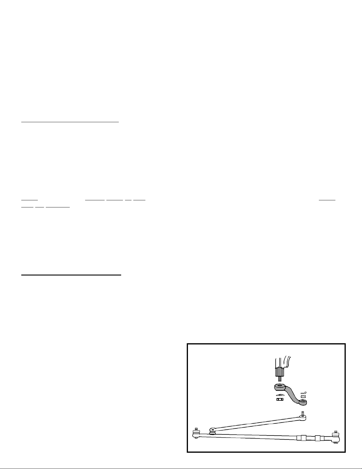
SA40 - International Scout II models. (This new pitman arm is approximately 2” shorter in length
than the original arm, and drops approximately 2” lower.)
T
o install the new pitman arm:
1. Remove the tie rod end from the pitman arm and lower tie rod down.
2. At the upper end of pitman arm, remove the nut and lock washer from the output shaft of the steering box.
3. With a puller, remove the old pitman arm and install the new arm, being sure to install the lock
washer and nut.
4. Install the tie rod back onto lower end of the pitman arm. Be sure to install the cotter pin after tightening the nut.
5. Check and tighten nuts periodically.
(REV. 03 10/93)
Steering Sector
Pitman Arm
Drag Link
Tie Rod
 Loading...