

Page 1
2007- 2012 Toyota FJ Cruiser 2.5"- 3”
Platinum Series Coil Over
Installation Instructions
Part # FJ730K
www.skyjacker.com
Part # Description Qty
TOY20153-S 2.5-3" COIL-2" COIL 2
SKY201-S SKYJACKER 2" SHOCK 2
T5USM-B UPPER SHOCK MOUNT 2
T5SBB-S SWAY BAR LWRG BLOCK 2
FJ25R 2.5" REAR COILS FJ 1
SBE702 END LINKS REAR 1
IMPORTANT NOTES
-Skyjacker strongly advises taking extreme caution when working with loaded coil springs to
prevent accident or harm.
-Trucks w/o manual locking hubs, the height must not be adjusted over 2" above OEM height.
-Both coil over assemblies should be adjusted to the same length (19 7/8" center to center)
after installation. It is VERY IMPORTANT that after installation, the coil does not have any
slack between the mounting cups. At no time during axle travel should the coils lose
contact with the mounting points.
-When final adjustments are made, the set screw MUST be tightened. At no time should the
coil over assembly be ran without the set screw being tight.
Front Installation:
1. With the vehicle on flat level ground, measure from center of the
front spindle to the top of the fender opening. Record this
measurement for later use.
2. Raise the front of the vehicle in the center of the front cross member,
using a floor jack.
3. Support the vehicle on the frame cross member so that the front tires
/ wheels are off the ground & remove the front tires / wheels.
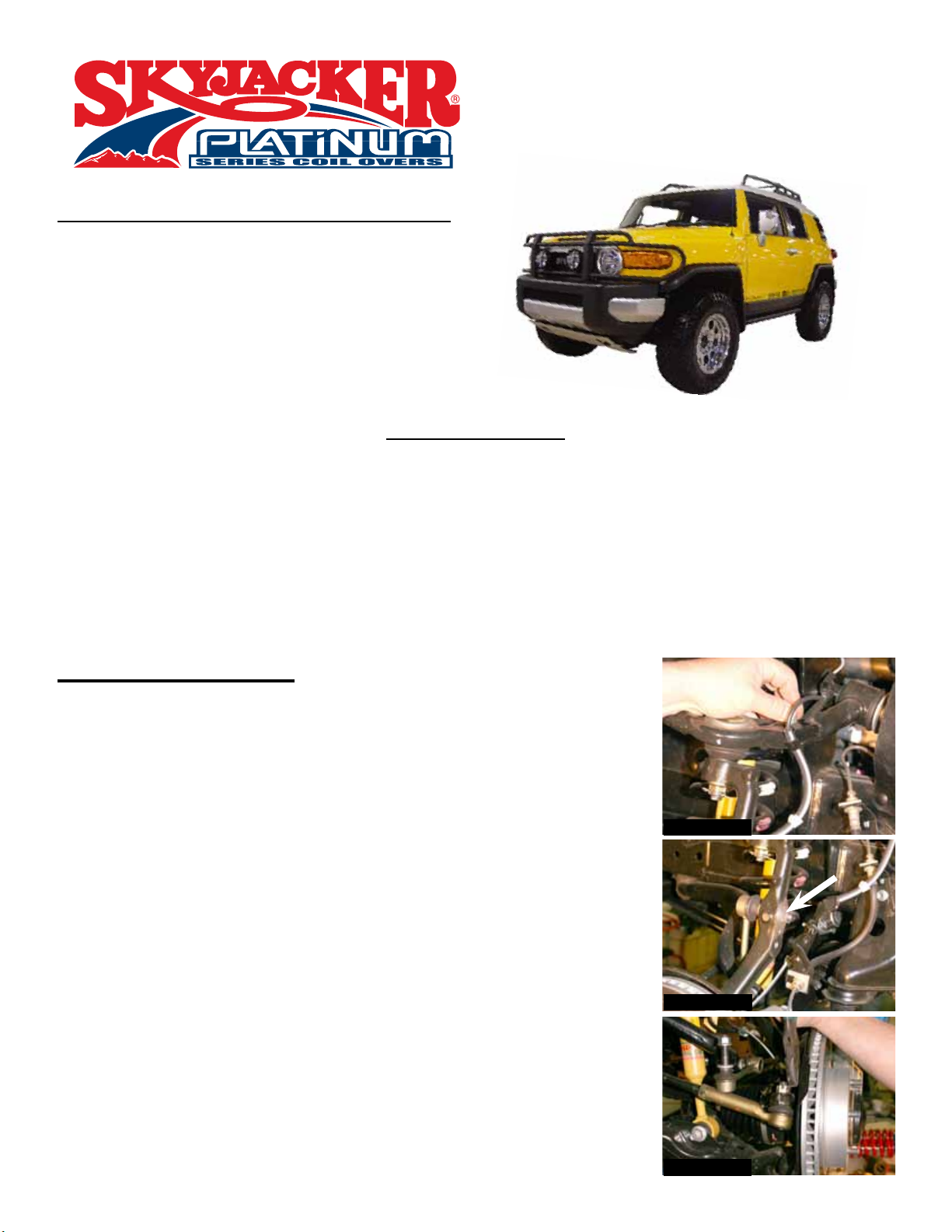
4. Remove the ABS line from the upper A-arms using a 10mm wrench.
(See Photo # 1) Disconnect ABS / brake line from the steering
knuckle.
5. Remove the sway bar end links using 17mm. (See Arrow in Photo
# 2)
6. Remove the cotter pin from the outer tie rod & disconnect tie rod
using a 12 mm socket. (See Photo # 3)
Photo # 1
Photo # 2
I-FJ730 REV2 12-12
Photo # 3
Pg 1
Page 2
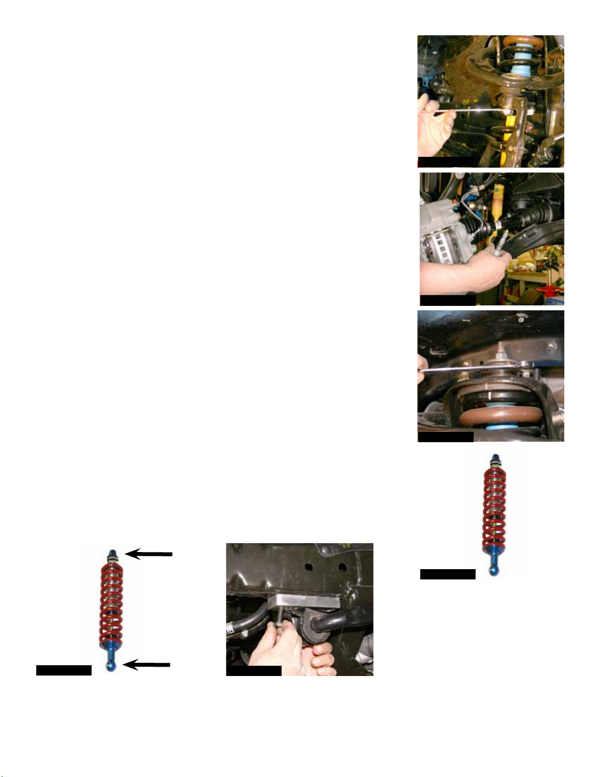
7. Remove the cotter pin from the upper ball joint & remove using a
19mm socket. (See Photo # 4)
8. Locate the lower shock mounting bolt & remove the lower shock
mounting bolt using a 19mm socket. (See Photo # 5)
9. Disconnect the upper shock assembly from the frame using a
14mm wrench. (See Photo # 6)
10. Disconnect the front sway bar from the frame.
11. Assemble the new Skyjacker coil over. (See Photo # 7) Attach the
new coil over to the new Skyjacker upper mounting bracket using
the 1/2" x 2 1/2” fine thread bolt, washers, & nut. Attach the new
coil over assembly to the OEM upper mount using the 7/16" x 1”
fine thread bolts, washers, & nuts. (See Photo # 8)
12. Attach the lower shock mount to the OEM location using the OEM
hardware. With the new coil over installed, use the supplied
spanner wrench to adjust the new coil over to measure 19 7/8"
center to center this should yield 2.5”- 3” of lift. (See Arrows in
Photo # 8)
13. Locate the new Skyjacker aluminum sway bar relocation brackets.
Attach new aluminum bracket to the OEM location in the frame
using the OEM hardware. The OEM bolts will mount through the
counter-sunk holes. Attach the sway bar in the new forward holes
using the supplied 10 x 20 mm bolts & 3/8” flat washers. (See Photo
# 9)
Photo # 4
Photo # 5
Photo # 6
14. Disconnect the sway bar end links from the sway bar. Place one
9/16” thick washer onto the threads & reattach the link to the sway
bar. This will allow adequate clearance between the sway bar link &
the new coil springs.
19 7/8"
Photo # 8
I-FJ730
Photo # 9
Photo # 7
Pg 2
Page 3
15. Reattach the ABS line / brake line & sway bar end links.
16. Reinstall the front tires / wheels & lower the vehicle to the ground.
Rear Installation:
17. Raise the rear of the vehicle & properly support the frame rails using
jack stands.
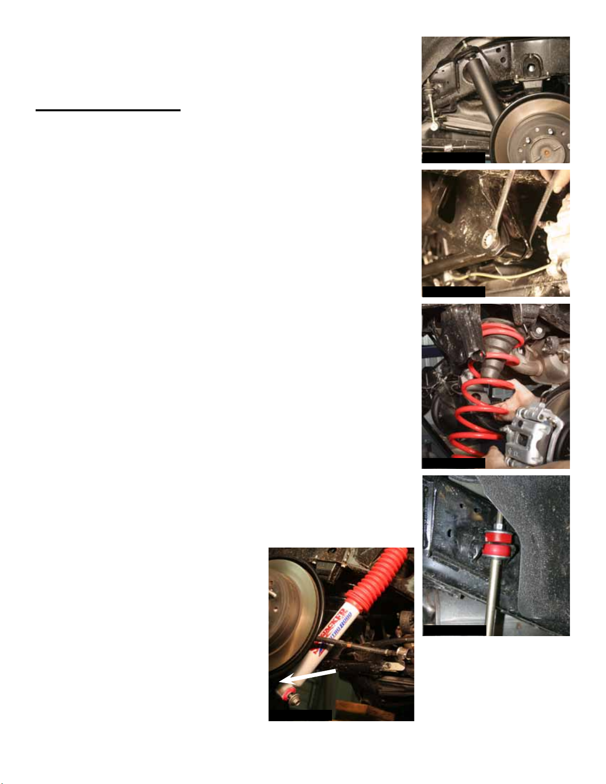
18. Remove the rear tires / wheels & rear shocks. (See Photo # 10)
19. It will be necessary to disconnect the brakeline brackets & sway bar
end links from the axle to allow for the installation of the new
Skyjacker rear coil springs. Disconnect the track bar from the frame.
(See Photo # 11)
20. Remove the OEM rear coil springs & replace with the new
Skyjacker rear coil springs. Be sure to retain the OEM upper bump
stop. (See Photo # 12)
Photo # 10
Photo # 11
21. Reattach the track bar & brakelines. Install the new Skyjacker sway
bar end links using the supplied bushings & hardware. (See Photo
# 13)
22. Install the new Skyjacker rear shocks. Be sure to install the
aluminum spacer supplied with the shock between the OEM mount
& the new rear shock. This will allow for proper clearance between
the shock body & axle. (See Arrow in Photo # 14)
23. Install the rear tires / wheels & lower the vehicle to the ground.
Photo # 12
I-FJ730
Photo # 13
Photo # 14
Pg 3
Page 4
FINAL NOTES:
* After the installation is complete, double check that all nuts & bolts are tight.
* Check to ensure there is adequate clearance between All rotating, mobile & fixed members. Check
the clearance between the inner side wall of tires.
* Ensure there is adequate clearance between the exhaust & brake lines, fuel lines, fuel tank, floor
board, & wiring harnesses. Check the steering gear for interference & proper working order.
Inspect the brake lines for damage & adequate clearance. Test the brake system.
* With the vehicle on the ground, cycle the steering lock to lock & inspect the steering, suspension,
drive line, & brake line systems for proper operation, tightness, & adequate clearance.
* Have a qualified alignment center realign the vehicle to the OEM specifications.
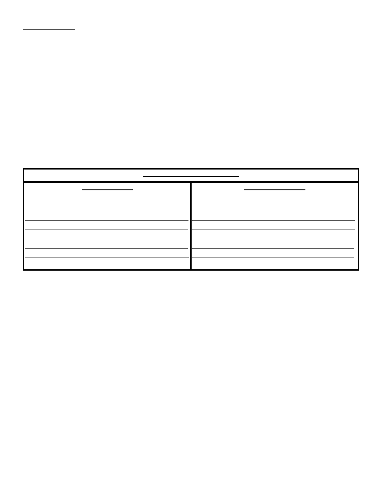
TORQUE SPECIFICATIONS
INCH SYSTEM
Bolt Size Grade 5 Grade 8
5/16 15 FT LB 20 FT LB
3/8 30 FT LB 35 FT LB
7/16 45 FT LB 60 FT LB
1/2 65 FT LB 90 FT LB
9/16 95 FT LB 130 FTLB
5/8 135 FT LB 175 FT LB
3/4 185 FT LB 280 FT LB
• The above specifications are not to be used when the bolt is being installed with a bushing.
Bolt Size Class 8.8 Class 10.9
6MM 5 FT LB 9 FT LB
8MM 18 FT LB 23 FT LB
10MM 32 FT LB 45 FT LB
12 MM 55 FT LB 75 FT LB
14MM 85 FT LB 120 FT LB
16MM 130 FT LB 165 FT LB
18MM 170 FT LB 240 FT LB
METRIC SYSTEM
Seat Belts Save Lives, Please Wear Your Seat Belt.
I-FJ730
Pg 4
 Loading...