

Page 1

Before beginning the installation, read these instructions and the enclosed driver’s “WARNING
NOTICE” thoroughly and completely. Also affix the “WARNING” decal in passenger compartment in
clear view of all occupants. If any of these items are missing from this instruction packet, do not
proceed with installation, but call SKYJACKER
®
to obtain needed items. If you have any questions or
reservations about installing this lift kit, call SKYJACKER®at 318-388-0816 for Technical Assistance
or Customer Service departments.
Make sure you park the vehicle on a level concrete or asphalt surface. Many times a vehicle is
un-level (side-to-side) from the factory, but usually not noticed until a lift kit has been installed
which makes the difference more visible. Using a measuring tape, measure the front and rear
(both sides) from the ground up to the center of the fender opening above the axle. Record below
for future reference. (NOTE: Due to OEM inconsistency and the available options, the amount of
lift gained by this lift kit can vary as much as 1/2".
Driver Side Front: Passenger Side Front:
Driver Side Rear: Passenger Side Rear:
NOTE: Ford made a design change to the front track bar and pitman on models made 3/99
and after (newer). Therefore, drop pitman arm part # FA499 is required on models built 03/99
and newer. The track bar on the newer models uses 20mm mounting hardware. Do not
attempt to modify new track bar relocation bracket(s) to fit these models. In the event you
need the other brackets, contact place of purchase for an exchange of bracket(s).
FRONT INSTALLATION:
1. The SOFTRIDE®front springs are center pinned so the spring can be installed with either end
toward the front or rear.
2. Open the hardware bag and apply a thin coat of lithium-based grease around the polyurethane
bushings and insert into each eye of the new front springs then apply a thin coat on the outside
of bushings. Insert one "thin wall" sleeve (will be the front eye of spring) and one "thick wall"
sleeve in each spring.
3. Raise front of vehicle and support securely with jack stands under the frame behind front springs
and block the rear wheels. Remove the tires, shocks, u-bolts (Caution
: once the u-bolts are
removed, the front axle will be free to move, so support securely on a floor jack).
4. Saving all hardware, unbolt front track bar from vehicle at frame on driver side (Note: if installing
6" or 8” lift, also remove track bar from mount on the axle on the passenger side). Remove
original track bar bracket from frame and crossmember (leave retainer clip inside frame rail).
1
#IF946M (4/02)
99 & UP
F250/F350 SUPER DUTY
AND EXCURSION 4",6" & 8"
INSTALLATION INSTRUCTIONS
Page 2
2
5. Disconnect the tie rod assembly from the original
pitman arm. Skyjacker's
®
new drop pitman arm is
needed for 4", 6" & 8" lifts (it is ordered separately in
4" and 6" kits, but included in the 8" kit box).
Remove pitman arm using a pitman arm puller, and
install new drop pitman arm. Be sure to install arm in
same direction as original arm (drag link hold end
pointing forward).
6. Remove front sway bar end links from the sway bar
(notice that they are offset to the inside at the top).
7. Unbolt each end of the original front leaf springs and
remove both springs from vehicle.
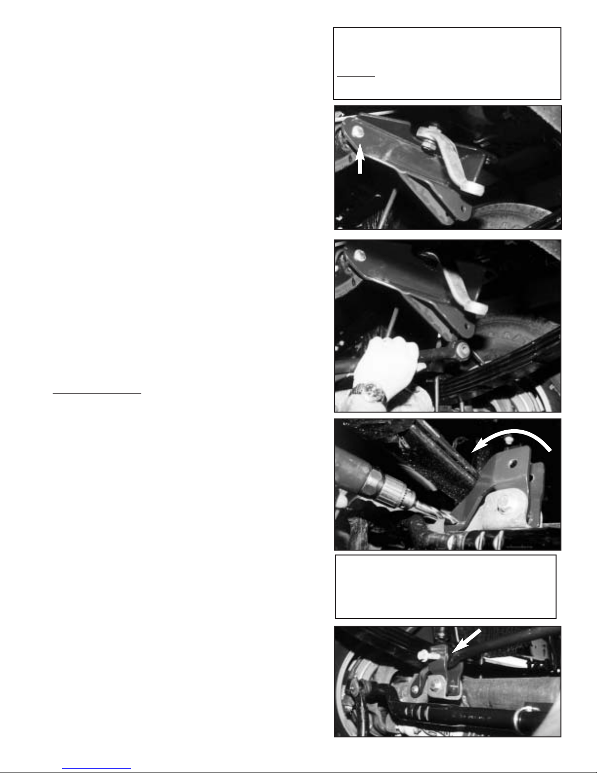
8. Attach new drop track bar bracket to frame using the
original bolts and retainer clip (inside frame rail).
Install new 1/2" x 2
1
⁄2" bolt with a washer into bracket
from the front, then through the crossmember using
a washer and lock nut on the back (see arrow in
Photo #1). NOTE: Some models may require slight
grinding to the crossmember for bracket to pull flush
against it. Tighten all track bar bracket bolts.
Reattach track bar to new drop bracket using
original hardware (Photo #2).
9. 6" & 8” Lifts Only
: NOTE: lower bracket for models
made 3/99 and newer, looks slightly different from
bracket shown in photos 3 & 4. Place new track bar
mounting bracket into original trackbar mount (Photo
#3). You may need to lightly tap bracket down in
place. (Rotate top of bracket toward passenger
side leaf spring until rear gusset is against
original trackbar mount, see arrow in photo #3)
Prior to 3/99 - Insert 9/16" x 31⁄2" bolt with
washer through original mounting hole and tighten
locknut to hold bracket in place. Using new brackets
left tab as a guide, drill 1⁄2" hole through outer OEM
Plate Only. Insert 1⁄2" x 11⁄2" bolt with washer and
tighten locknut. Reattach track bar using original
hardware (Photo #4). Completely tighten all
hardware.
3/99 and Newer - Insert new 20mm x 90mm bolt
through original mounting hole using new 20mm
locknut provided, and tighten to hold bracket in
place. Using new brackets left tab as a guide, drill
9/16" hole through both the inner and outer OEM
plates. Be sure to keep drill bit level vertically and
horizontally. Insert 1" long spacer at new drilled
hole, inside the original mounts. Insert 9/16" x 3"
bolt with washer thru spacer and tighten locknut.
Reattach track bar using original hardware (Photo
#4). Completely tighten all hardware.
PHOTO #1
PHOTO #2
PHOTO #3
PHOTO #4
Here’s A Tip: Have a friend turn the
steering wheel slightly from left to right,
this will aid in aligning the trackbar to the
trackbar bracket hole. See arrow below.
NOTE: Track bar brackets will only work with the
Skyjacker specific application height of lift springs.
DO
NOT combine with other manufactures lift kit
components.
Page 3
3
10.Install the new springs with the "thin wall" sleeves toward the
front bumper. Do not fully tighten spring and shackle bolts at
this time. (NOTE: It is important to NOT
fully tighten the
spring and shackle bolts at this time on these SOFTRIDE
®
springs because with no load being applied on the
springs, a false lift and stiff ride will result. These bolts will
be fully tightened later once the vehicle is on the ground
with the weight on the springs.) Install new front U-Bolts
and torque to 85-90 ft. lbs.
11. Reattach drag link assembly to new drop pitman arm being
sure to reinstall cotter pin. On 8" kits, install the provided front
brake lines using the instructions inclosed.
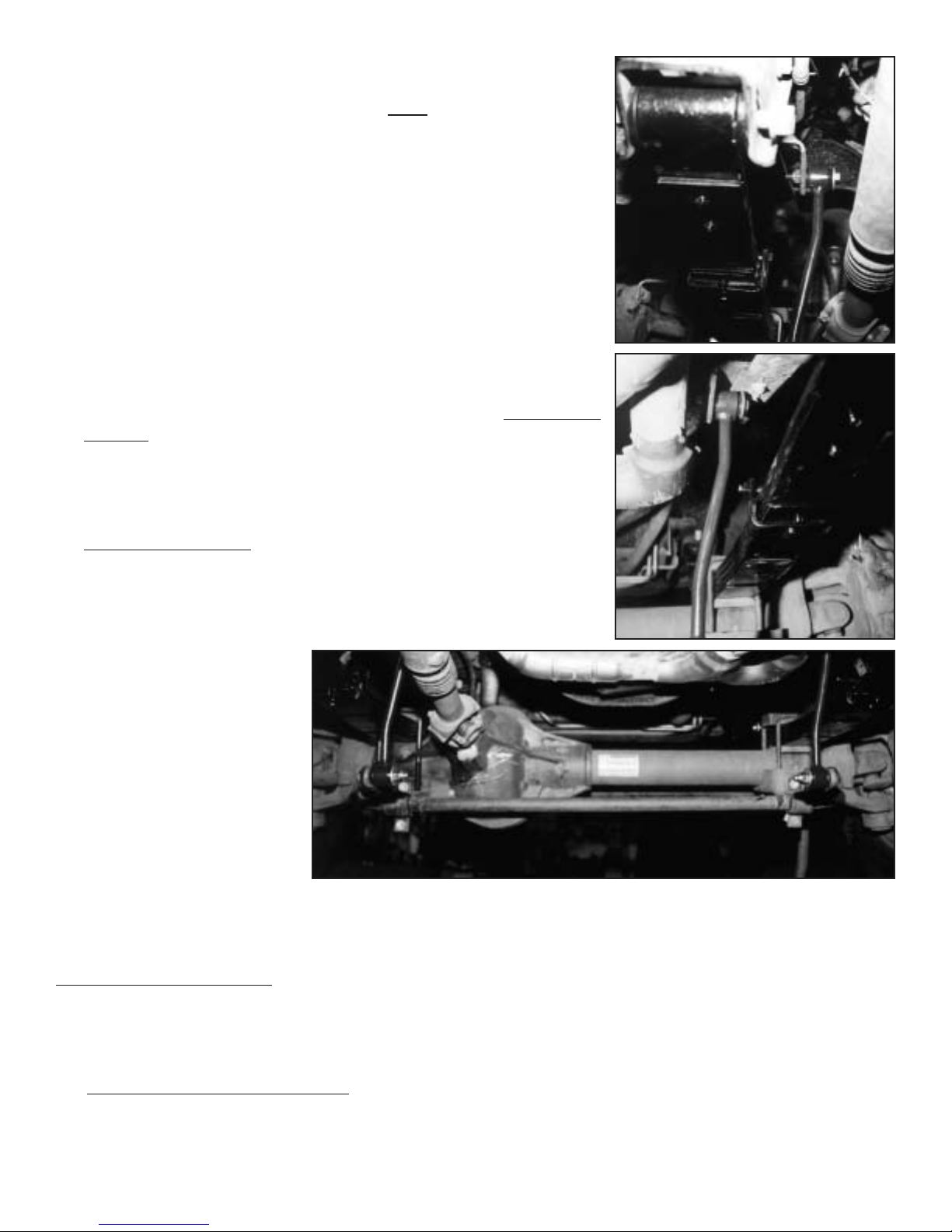
12.Open sway bar end link hardware bag. Insert a bushing and
metal sleeve #51792 into each eye. Install the new end links
beginning with the top driver's side (see photo #5, shown from
the rear). Insert new 12mm bolt and large washer from the
inside through end link eye then mounting tab and tighten with
12mm nut.
Next install the top of passenger's side end link (see photo #6,
shown from the rear
). Insert new 12mm bolt and large washer
from the outside through end link eye then mounting tab and
tighten with 12mm nut.
Now connect the sway bar to end link inserting new 1/2 x 3"
bolts through mount (from
outside) then through end
link with a large washer
and lock nut on the inside
as shown in photo #7.
Once both side are
installed, completely
tighten bolts.
13.Install new shocks at this
time. If purchased
Skyjacker's
®
triple shock kit, refer to its instructions at this time.
14.Install tires and lower vehicle to ground.
Now completely tighten the spring eye and shackle bolts on each side.
TO INST
ALL THE REAR:
15. Raise rear and support securely with jack stands and block the front wheels. Remove the tires,
shocks, u-bolts and vent tube on differential. (CAUTION: the rear axle will now be free to
move, so support securely on floor jack.)
16. New rear leaf spring installation
: Unbolt and remove the stock rear springs and bolt up the new
rear springs with long end of spring towards rear bumper. (NOTE: be sure thick end of bottom
degree shim is also towards rear bumper.) The original blocks are maintained.(on vehicles built
prior to march '99 the block is removed on 4" Systems with rear springs).
PHOTO #5
PHOTO #6
PHOTO #7
Page 4
17. Rear block installation
: Install the new lift blocks, taller end toward the rear bumper, between
springs and original blocks (new block will be installed on top of the original block).On 8" kits,
install the provided rear brake lines using the instructions enclosed.
18. Using the floor jack, raise the axle up to rear springs. Be sure the spring tie bolts and block pins
all align in proper holes and are completely seated. Install and torque new u-bolts to 100-110 ft.
lbs.
19. Install rear sway bar endlinks (supplied only in 8" kit or ordered optionally w/ 4" & 6" kits). Install
new shocks and tires, then lower vehicle to ground.
NOTES:
• If vehicle is equipped with rear sway bars, you need to order the following extended sway
bar end links: #SBE404 for 4" lifts #SBE405 for 6" lifts
• According to Ford manuals there is a 3/4" tolerance on side to side height differences
from factory. If you are having this problem after installation, please call for further
options.
• On models equipped with a rear carrier bearing, if a driveline vibration occurs, it may be required
to lower carrier bearing after installation of this lift.
4-6" Lifts use Skyjacker Part # CBL3401 8" Lifts use Skyjacker Part # CBL214
• Be sure to have front end alignment checked periodically by a professional for your safety and
longer tire life.
• Check drive shafts for proper length and clearance. Check brake line length; it may be necessary
to re-route original lines or replace with new longer stainless steel lines available from SKYJACKER
®
.
• It may be necessary to recenter the steering wheel by adjusting the turn buckle on the drag link
assembly.
NOTICE: Retorque ALL nuts, bolts and especially the u-bolts after the first 100 miles,
again after another 100 miles, and then check periodically thereafter.
Torque Specifications:
7
⁄16" Bolts ............55 - 58 ft.lbs.
1
⁄2" Bolts ..............85 - 90 ft.lbs.
9
⁄16" Bolts ............115 - 125 ft.lbs.
9
⁄
16
" Front U-Bolts .........85 - 90 ft.lbs.
5
⁄8" Rear U-Bolts ..........100-110 ft. lbs
12mm Bolts ...........73-77 ft.lbs.
ACCESSORIES:
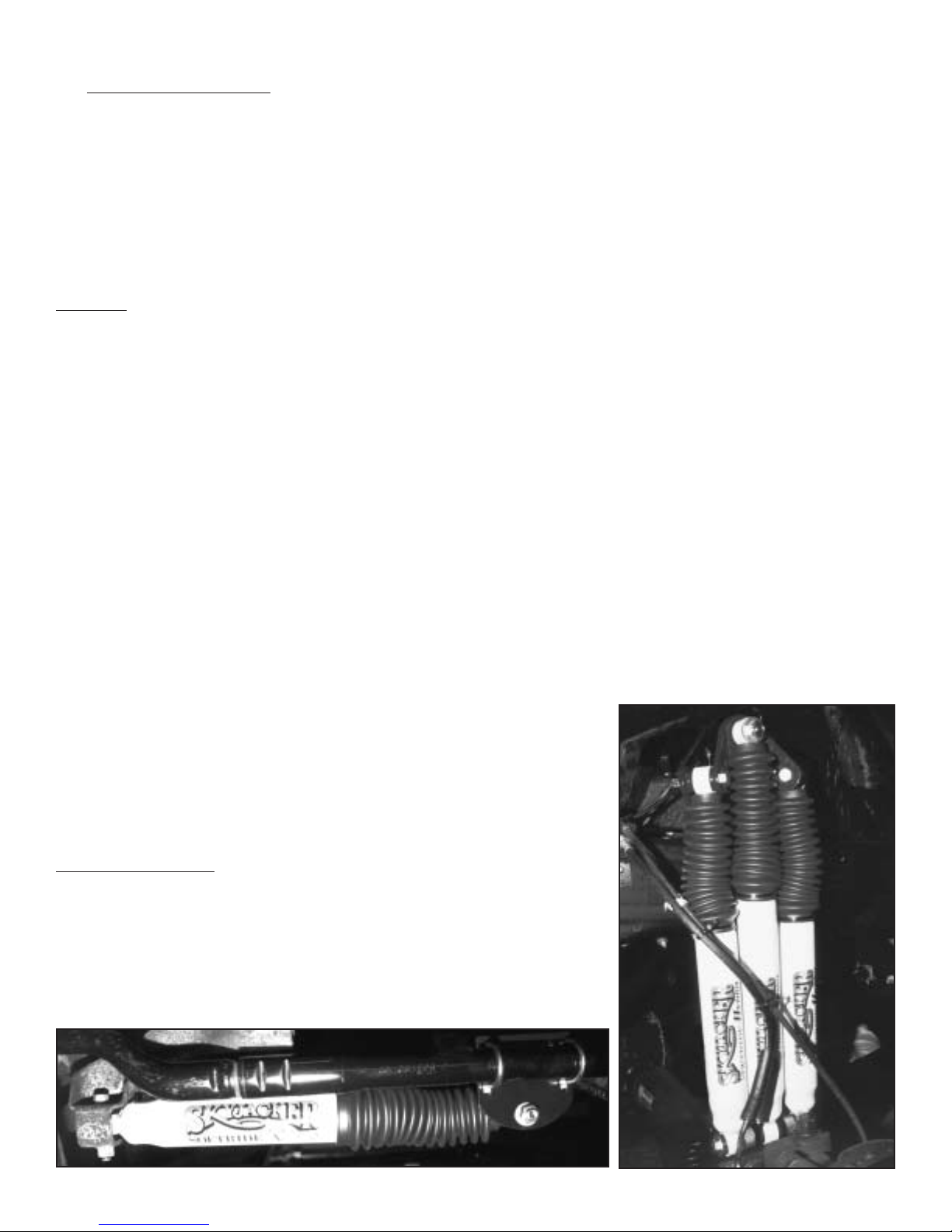
• Triple Front Shock Kit (Shown at right) #TS950
• HD OEM Replacement Steering Stabilizer #7099
• Single Steering Stabilizer (Shown below) #7199
• Dual Steering Stabilizer #7299
The SOFTRIDE
®
rear springs are also available separately.
TS950
7199
4
Page 5

PITMAN ARM
INSTALLATION INSTRUCTIONS
(Find proper application listed below)
Figure 1
FA400/FA600 -fits FORD 1980-96 F150/Bronco, 83-97 Ranger/Bronco II, 90-94 Explorer,
80-98 F250/F350, and 99 F250/F350 Super Duties through 2/99. Power steering
required.
FA499/FA699 -fits FORD 99 F250/F350 Super Duty from 3/99 and newer. Power steering required.
See Figure 4 for proper assembly diagram.
Figure 2
JA150 - fits 76-86 CJ5 and CJ7 with manual steering.
JA250 - fits 76-86 CJ5 and CJ7 with power steering.
JA350 - fits 74-86 Cherokee Chief, Grand Wagoneer, Truck series 20,40,J10,J20 4WD with ps.
JA552 - fits 72-75 CJ with 1.5-2.5” lift and power steering.
JA550 - fits 72-75 CJ with 3-4” lift and power steering.
JA652 - fits 72-75 CJ with 1.5-2.5” lift and manual steering.
JA650 - fits 72-75 CJ with 3-4” lift and manual steering.
JA750 - fits 87-96 Wrangler YJ, and 97-up Wrangler TJ with 3-4" lift models with power steering.
JA850 - fits 87-96 Wrangler YJ, and 97-up Wrangler TJ with 3-4" lift models with manual steering.
T
o install the new pitman arm:
1. Remove the tie rod end from the pitman arm and lower tie rod down.
2. At the upper end of pitman arm, remove the nut and lock washer from the output shaft of the
steering box.
3. With a puller, remove the old pitman arm and install the new arm, being sure to install the lock
washer and nut.
4. Install the tie rod back onto lower end of the pitman arm. Be sure to install the cotter pin after
tightening the nut.
5. Check and retighten nuts periodically.
Figure 1 Figure 2
Steering Sector Steering Sector
Pitman Arm
Pitman Arm
Drag Link
Tie Rod
Drag Link
Tie Rod
#I-ARM1 (Rev. 12/00)
Page 6
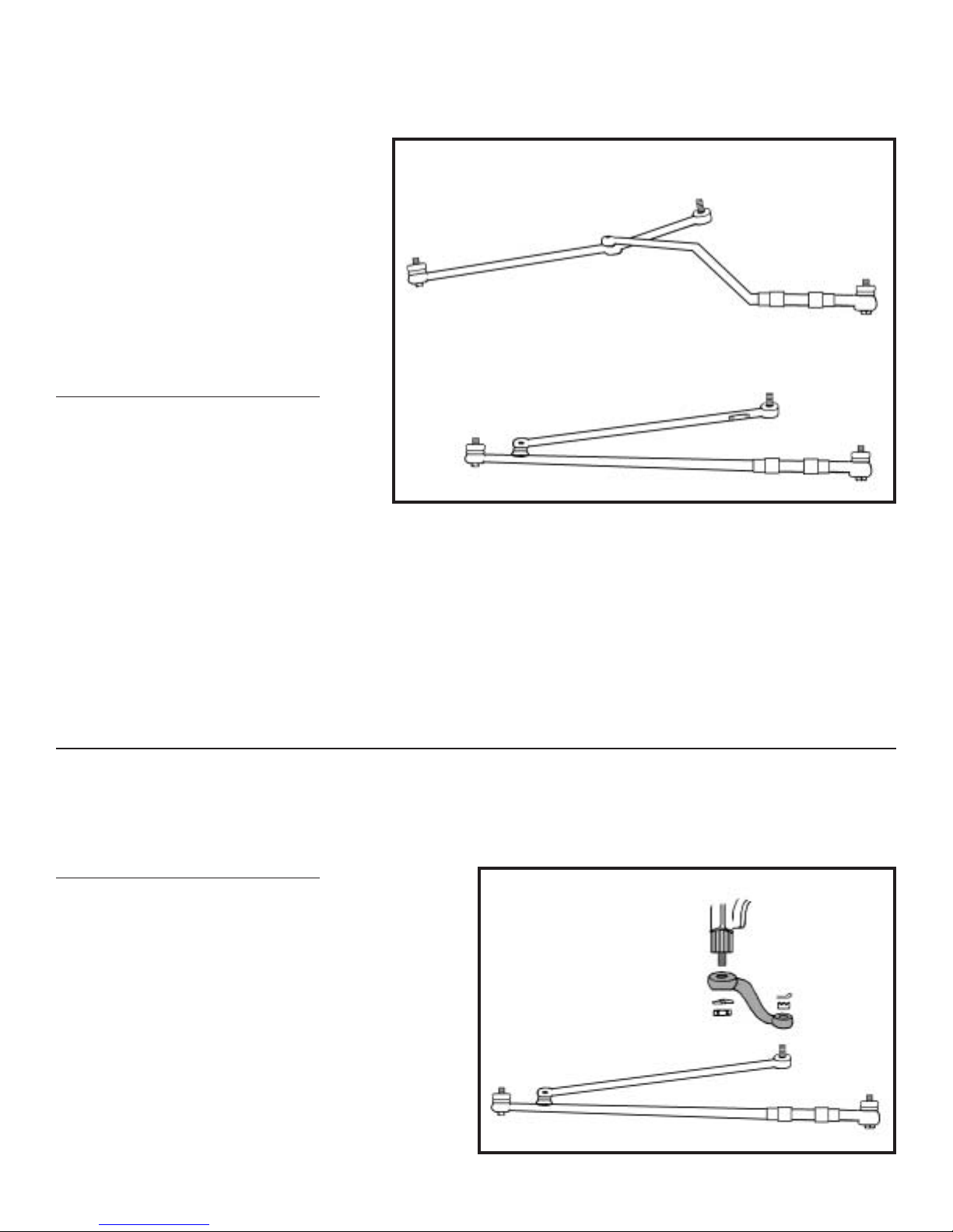
Figure 3
FA300 - fits 1976-79 Ford F100 and F150 with power steering, 78-79 Bronco with power steering,
and 66-77 Bronco (with or without power steering)
NOTE: This pitman arm (FA300) is a
direct factory replacement. However,
on models equipped with “scissor
style” steering (see Figure 3), found
on the 1976-77 F100, F150 and old
model Bronco, the drag link and tie
rod assembly will require changing to
the “straight style” in order to install a
drop pitman arm.
T
o install the new pitman arm:
1. Remove the tie rod end from the
pitman arm and lower tie rod down.
2. At the upper end of pitman arm,
remove the nut and lock washer
from the output shaft of the
steering box.
3. With a puller, remove the old pitman arm and install the new arm, being sure to install the lock
washer and nut.
4. Install the tie rod back onto lower end of the pitman arm. Be sure to install the cotter pin after
tightening the nut. (If you changed the style of steering rods, do not forget to reset the toe-in and
toe-out and tighten all of the tie rod assembly.)
5. Check and retighten periodically.
Figure 4
SA40 - International Scout II models. (This new pitman arm is approximately 2” shorter in length
than the original arm, and drops approximately 2” lower.)
To install the new pitman arm
:
1. Remove the tie rod end from the pitman arm
and lower tie rod down.
2. At the upper end of pitman arm, remove the
nut and lock washer from the output shaft of
the steering box.
3. With a puller, remove the old pitman arm and
install the new arm, being sure to install the
lock washer and nut.
4. Install the tie rod back onto lower end of the
pitman arm. Be sure to install the cotter pin
after tightening the nut.
5. Check and tighten nuts periodically.
Figure 3
“Scissor Style”
“Straight Style”
Figure 4
Steering Sector
Pitman Arm
Drag Link
Tie Rod
 Loading...