

Page 1

2001 - 2010 GM 2500 HD 4WD
2002- 2010 GM Hummer H2
Heavy Duty OEM
www.skyjacker.com
REQUIRED TOOL LIST:
• Safety Glasses
• Metric / Standard Wrenches & Sockets
• Torque Wrench
Before beginning the installation, thoroughly & completely read these instructions. Please refer to
the Parts List to insure that all parts & hardware are received prior to the disassembly of the vehicle.
If any parts are found to be missing, contact SKYJACKER® Customer Service at 318-388-0816 to
obtain the needed items. If you have any questions or reservations about installing this product,
contact SKYJACKER® Technical Assistance at 318-388-0816.
Steering Stabilizer
Installation Instructions
Component Box Breakdown:
Part #: 7098 / 9098
Item # Description Qty Item # Description Qty
7202WS WHITE STEERING DAMPER 1 BTIE-K BLACK BOOT TIE 1
(Included With 7098) (Included With 9098)
9202WS SILVER STEERING DAMPER 1 HSS HYDRO SHOCK DECAL 1
(Included With 9098) (Included With 7098)
B12RS RED BOOT 1 SSD SILVER STABILIZER DECAL 1
(Included With 7098) (Included With 9098)
B12KS BLACK BOOT 1 HB-7098 HARDWARE BAG: 7098 / 9098 1
(Included With 9098) I-7098 INST SHEET: 7098 / 9098 1
BTIE RED BOOT TIE 1
(Included With 7098)
Hardware Bag Breakdown:
Part # HB-7098
Item # Description Qty Item # Description Qty
HOURGLASS 5/8 HOURGLASS 5/8 BUSHING 1 P837 STAB TAPERED STUD 1
HG58125 HOURGLASS 5/8" X 1.25" 1 403712 ES22 SLEEVE / 1.25" LONG 1
I-7098 REV2 12-13
Pg 1
Page 2
Installation:
1. Park the vehicle on a level concrete or asphalt surface with
the front tires / wheels pointing straight forward.
2. Set the emergency brake & block the rear tires / wheels.
3. Remove the OEM steering stabilizer from the frame & from
the center steering link.
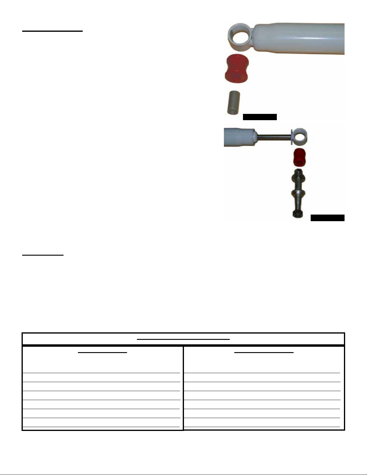
4. Install the supplied 1 1/4” long bushing into the body end of
the new Skyjacker steering stabilizer & install the supplied
1 1/4” long sleeve into the new bushing. (See Photo # 1)
5. Install the supplied 5/8” hourglass bushing, which is 1 1/2”
long, into the shaft end of the new Skyjacker steering
stabilizer. (See Photo # 2)
6. Install the supplied tapered stud into the OEM center
steering link using the supplied nut & washer. Slide the
shaft end of the new Skyjacker steering stabilizer over the
stud & install the supplied nut & washer. (See Photo # 2)
7. Attach the body end of the new Skyjacker steering stabilizer
to the OEM mount on the frame using the OEM hardware.
Final Notes:
• After the installation is complete, double check that all nuts & bolts are tight. Refer to the following
chart for the proper torque specifications. (Do not retighten the nuts & bolts where thread lock
compound was used.)
Photo # 1
Photo # 2
• Cycle the steering of the vehicle left to right & check all parts for adequate clearance.
• After the first 100 miles, check all of the hardware for the proper torque & periodically thereafter.
TORQUE SPECIFICATIONS
INCH SYSTEM
Bolt Size Grade 5 Grade 8
5/16 15 FT LB 20 FT LB
3/8 30 FT LB 35 FT LB
7/16 45 FT LB 60 FT LB
1/2 65 FT LB 90 FT LB
9/16 95 FT LB 130 FTLB
5/8 135 FT LB 175 FT LB
3/4 185 FT LB 280 FT LB
• The above specifications are not to be used when the bolt is being installed with a bushing.
I-7098 Pg 2
Bolt Size Class 8.8 Class 10.9
6MM 5 FT LB 9 FT LB
8MM 18 FT LB 23 FT LB
10MM 32 FT LB 45 FT LB
12 MM 55 FT LB 75 FT LB
14MM 85 FT LB 120 FT LB
16MM 130 FT LB 165 FT LB
18MM 170 FT LB 240 FT LB
METRIC SYSTEM
 Loading...