

Page 1

OPERATING MANUAL
This manual MUST be kept and stored with the aerial platform at all times.
SJ-800E
TM
Series
Battery Powered
For Service please call .....................................................................800 275-9522
Skyjack Inc. Service Center 3451 Swenson Ave., St. Charles, IL. 60174.... FAX 630 262-0006
For Parts in North America and Asia please call ....................................
Skyjack Inc. Parts Center 3451 Swenson Ave., St. Charles, IL. 60174 ..............F AX 888 782-4825
For Parts & Service in Europe please call....................................................
Skyjack Europe Communicatieweg 29, 3641 SG Mijdrecht Netherlands .............FAX 31 297 256 948
117131AH Printed in Canada Mar . 2002
800 965-4626
31 297 255 526
Page 2

WARNING
This Operating Manual and the “ ANSI/SIA Manual Of Responsibilities” are considered
fundamental parts of the elevating work platform. They are a very important way to
communicate necessary safety information to users and operators. A complete and
legible copy of these manuals MUST BE KEPT ON THE WORK PLATFORM in the
provided weather resistant storage compartment at all times.
Page 3

Table Of Contents
Section - Paragraph Page No.
Section 1 - Introduction
Purpose Of Equipment .................................................................................................................... 7
Use Of Equipment............................................................................................................................7
Warnings...........................................................................................................................................7
Description .......................................................................................................................................7
Operator Warnings ...........................................................................................................................8
Specifications And Features ............................................................................................................ 9
Standard Features And Optional Equipment ............................................................................... 10
Work Platform Major Component Identification ........................................................................... 11
Section 2 - Operation
Operating Controls Identification ........................................................................................... 13
Base Controls .................................................................................................................................13
Electrical Panel .............................................................................................................................. 13
Emergency Battery Disconnect Switch ........................................................................................13
Base Control Station ...................................................................................................................... 14
1500W AC Inverter (Option)...........................................................................................................14
Platform Controls ........................................................................................................................... 15
Operators’s Control Box ................................................................................................................15
Powered Extension Platform Control Box .................................................................................... 15
Outrigger Control Box ....................................................................................................................15
Identification And Operation Of Safety Devices ............................................................................16
Operator Qualifications ........................................................................................................... 17
Operating Procedures ............................................................................................................. 17
Set-Up Procedure ...........................................................................................................................17
Prestart Checks ..............................................................................................................................18
Start and Operation ....................................................................................................................... 19
Emergency Lowering System .......................................................................................................20
Shutdown Procedure .....................................................................................................................20
Winching and Towing Procedures ................................................................................................ 21
Outrigger Operating Procedures ...................................................................................................22
Electrical Inverter (Option) .............................................................................................................23
Battery Service And Charging Procedures...................................................................................23
Battery Charger Operation ............................................................................................................24
Bycan Charger Operation (4825U) ............................................................................................... 24
MAC Charger Operation (#BA1045)............................................................................................. 25
MAC Charger Operation (#BA1001)............................................................................................. 26
S
E
C
T
I
O
N
I
N
D
1
2
List Of Tables
TABLE 1-1. Specifications And Features ...................................................... Section 1, Page 9
TABLE 1-2. Standard Features And Optional Equipment ........................... Section 1, Page 10
TABLE 2-1. Owner’s Annual Inspection Record........................................... Section 2, Page 27
TABLE 2-2A. Maximum Platform Capacities................................................... Section 2, Page 28
TABLE 2-2B. Maximum Platform Capacities ................................................... Section 2, Page 29
TABLE 2-3. Maintenance And Inspection Schedule .................................... Section 2, Page 30
SJ-800E Series Battery Powered
117131AH
Mar . 2002
E
X
Page 3
Page 4
WARNING
ANSI/SIA (United States)
You are required by the current ANSI/SIA A92.6 standards to read and understand YOUR
RESPONSIBILITIES in the Manual Of Responsibilities before you use or operate this work platform.
CSA (Canada) and CE (Europe)
You are required to conform to national health and safety regulations applicable to the operation of this
elevating work platform.
FAIL URE TO COMPLY with your REQUIRED RESPONSIBILITIES in the use and operation of the
work platform could result in DEATH OR SERIOUS INJURY!
OPERATOR SAFETY REMINDERS
The National Safety Council reminds us that most accidents are caused by the failure of some individuals to
follow simple and fundamental safety rules and precautions. Common sense dictates the use of protective
clothing when working on or near machinery. Use appropriate safety devices to protect your eyes, ears,
hands, feet and body.
You, as a careful operator, are the best insurance against an accident. Therefore, proper usage of this work
platform is mandatory. The following pages of this manual should be read and understood completely before
operating the work platform. Any modifications from the original design are strictly forbidden without written
permission from SKYJACK, Inc.
DANGER
ELECTROCUTION HAZARD
THIS MACHINE IS NOT INSULATED. MAINTAIN SAFE CLEARANCES FROM ELECTRICAL
POWER LINES AND APPARATUS. YOU MUST ALLOW FOR PLATFORM S WAY, ROCK OR SAG.
THIS WORK PLATFORM DOES NOT PROVIDE PROTECTION FROM CONTACT WITH OR
PROXIMITY TO AN ELECTRICALLY CHARGED CONDUCTOR.
Minimum Safe Approach Distance
ANSI/SIA A92.6-1999 &
CSA CAN3-B354.2&.3-M82 Requirements
Voltage Range
(Phase to Phase) Feet Meters
0 To 300V Avoid Contact
Over 300V to 50KV 10 3.05
Over 50KV to 200KV 15 4.60
Over 200KV to 350KV 20 6.10
Over 350KV to 500KV 25 7.62
Over 500KV to 750KV 35 10.67
Over 750KV to 1000KV 45 13.72
Minimum Safe Approach Distance
“Avoidance of danger from Overhead Lines”
These machines should not operate within 15M
of overhead lines suspended from steel towers.
These machines should not operate within 9M of
overhead lines suspended from wooden poles.
FAILURE TO AVOID THIS HAZARD WILL RESULT IN DEATH OR SERIOUS INJURY!
CE Guidance Note
Page 4
SJ-800E Series Battery Powered
Mar . 2002
117131AH
Page 5
DO NOT OPERATE THIS EQUIPMENT WITHOUT PROPER
AUTHORIZATION AND TRAINING. DEATH OR SERIOUS
INJURY COULD RESULT FROM IMPROPER USE OF THIS
EQUIPMENT!
SERVICE POLICY AND WARRANTY
SKYJACK, Inc. warrants each new SJ800E Series work platform to be free of defective parts and workmanship
for the first 12 months. Any defective part will be replaced or repaired by your local SKYJACK dealer at no
charge for parts or labor. Refer to Warranty Statement for extensions or exclusions.
NOTE
SKYJACK, Inc. is continuously improving and expanding product features on it’s equipment, therefore,
specifications and dimensions are subject to change without notice.
This Safety Alert Symbol Means Attention!
Become Alert! Your Safety Is Involved.
The Safety Alert Symbol identifies important safety messages on machines, safety signs, in manuals, or elsewhere. When you see this symbol, be alert to the possibility of personal injury or death. Follow the instructions
in the safety message.
SCOPE OF THIS MANUAL
This manual applies to the ANSI/SIA, CSA and CE versions of the SJ800E Series work platform models listed on
Table 1-1. Equipment identified with “ANSI” meets the ANSI/SIA-A92.6 -1990 or ANSI/SIA-A92.6 -1999 standards.
Equipment identified with “CSA” meets the CAN3-B354.2&.3-M82 standards. Equipment identified with “CE”
meets the requirements for the European countries, i.e. Machinery Directive 89/392/EEC and EMC Directive 89/
336/EEC and the corresponding EN standards.
SJ-800E Series Battery Powered
117131AH
Page 5
Mar . 2002
Page 6

Warranty Statement
SKYJACK, Inc. warrants each new work platform to
be free of defective parts and workmanship. During
the first full year, labor and replacement parts will be
provided by the local authorized Skyjack dealer
without charge. For the following 48 months,
structural components found to be defective will be
replaced or repaired at no charge.
A warranty registration card is supplied with each
work platform. The warranty is only effective when
the warranty card has been completed and returned
to Skyjack within 15 days from the time of billing.
When work platforms are put into stock, the warranty
period does not start until the work platform has been
shipped to the dealers customer. If a unit is put into
service and no warranty card has been mailed to
Skyjack, Inc., the warranty period will commence 15
days from the date the dealer was invoiced for the
work platform.
All warranty claims are subject to approval by
Skyjack’s Service Department. Skyjack, Inc. reserves
the right to limit or adjust claims with regard to
defective parts, labor or travel time based on usual
and customary guidelines. Parts purchased from
sources other than Skyjack will not be covered under
this warranty. Misuse or improper operation, lack of
normal maintenance and inspections as outlined in
this Operating/Maintenance and Parts Manual,
alterations to original design and/or components or
accidents will void all warranty. Batteries are not
covered by this warranty.
The above mentioned warranty statement is exclusive
and no other warranty whether written, oral or implied
shall apply. Skyjack excludes any implied warranty
of merchantability and fitness and accepts no liability
for consequential damages or for other negligence.
WARRANTY PROCEDURES
The selling distributor or authorized dealer shall be
responsible for the complete handling of customer
claims under this warranty. Here’s what to do:
3. Fill out a Warranty Claim Form from dealer’s supply of
claim forms. Then notify Skyjack’s Service Department
of the warranty claim number on the form used.
4. The distributor/dealer should then file a warranty claim
with Skyjack, Inc. describing the nature of the defect,
probable cause, work performed, travel hours, and labor
hours listed separately . Warranty labor will be paid at a
rate of $42.00 per hour. The travel allowance will be
paid at the same hourly rate within the dealers specified
territory , limited to a maximum of four (4) hours. If a part
has serviceable components, PLEASE replace the bad
component. For instance, if you have a bad switch on a
controller , please replace the switch. Hydraulic cylinders
should be resealed, unless they are damaged beyond
repair . Engine failures should be directed to your local
engine distributor and covered by the manufacturers
warranty . Skyjack will accommodate you and your labor.
Labor rates and travel allowances are subject to change
without notice.
5. Warranty claims must be received by Skyjack within
15 working days from the date of the repair . Warranty
claims received with insufficient information will be
returned for correction or completion.
6. Materials returned for warranty inspection must have
the following procedures:
A. Carefully packaged to prevent additional damage
during shipping.
B. Drained of all contents and all open ports capped
or plugged.
C. Shipped in a container tagged or marked with the
RA number .
D. Shipped PREPAID. Any item(s) returned for warranty
by any other means may be refused and returned unless
prior approval from Skyjack is obtained.
E. Items shipped to the dealer will be sent freight
prepaid and added to the invoice.
1. When a customer files a claim under this warranty,
contact Skyjack’s Service Department to verify
warranty coverage. NOTE: The complete serial
number of the work platform is required to verify
the claim.
2. When Skyjack’s Service Department verifies
warranty coverage, they will also issue an RA
(Return Authorization) number for the return of any
defective component(s). All items over $25.00 in
value must be returned to Skyjack, Inc.
Page 6
Mar . 2002
Failure to comply with the above procedures may delay
approval and processing of the warranty claim and could
result in the denial of a warranty claim. Skyjack’s dealer’s
accounts must be kept current in order to approve and
issue warranty credits. Skyjack reserves the right to withhold issuance of warranty credits to a dealer if their account is not in good standing. This is subject to change
without prior notice.
SJ-800E Series Battery Powered
117131AH
Page 7

SECTION 1
INTRODUCTION
Purpose Of Equipment
The SKYJACK SJ-800E Series Work Platform is
designed to transport and raise personnel, tools and
materials to overhead work areas.
Use Of Equipment
The work platform (Figure 1-1.) is a highly
maneuverable, mobile work station. Lifting and
elevated driving MUST be on a flat, level, compacted
surface. The work platform can be driven over uneven
terrain only when the platform is fully lowered.
Warnings
The operator MUST read and completely understand
the safety panel label located on the platform and
ALL other warnings in this manual and on the work
platform. Compare the labels on the work platform
with the labels found throughout this manual. If any
labels are damaged or missing, replace them
immediately.
Description
The work platform consists of three major assemblies,
the platform, lifting mechanism and the base. An
operator’s control box is mounted on the platform
railing. Auxiliary and emergency controls are located
at the base.
Platform
The platform is constructed of a tubular support frame,
a skid-resistant “diamond plate” deck surface, and
43-1/2" (1.10m) hinged railings with 6" (15.24cm) toe
boards and mid-rails. The platform can be entered
from either side through a spring returned gate. All
models can be equipped with a front or both front
and rear extension platforms.
Base
The base is a rigid one-piece weldment which
supports two component side cabinets. One cabinet
contains the hydraulic components, up/down
controls and electrical components. The other
cabinet contains the hydraulic tank. The front axle
has two wheels, steerable by a hydraulic cylinder
and is non-driven or drive shaft/gear box driven (4WD
option). The rear axle is drive shaft/gear box driven
and has a spring-applied hydraulically-released disc
parking brake. The drive system is designed to
automatically adjust to rough terrain or steep
inclines. A slide-out drawer at the front of the base,
supports a battery compartment which provides
power to the electrical system.
Operator’s Control Box
A removable control box, mounted at the right front
of the platform, contains controls for work platform
motion and emergency stopping.
Manual Storage Box
This weather resistant box is mounted to the inside
of the hydraulic cabinet door at the base. It contains
the Operating Manual, the Operating/Maintenance
and Parts Manual and other important
documentation. The Operating Manual for this make
and model work platform MUST remain with the work
platform and should be stored in this box.
Hydraulic Outriggers (if equipped)
Hydraulic outriggers are mounted to the four corners
of the base. Controls on the operator’s control box
are used to extend and retract the hydraulic outrigger
cylinders.
1
Lifting Mechanism
The lifting mechanism is constructed from steel tubing
making up a scissor-type assembly. The scissor-type
assembly is raised and lowered by single-acting
hydraulic lift cylinders with holding valves. A singlesection pump, driven by the electric traction motor
through a gear box provides hydraulic power to the
lift cylinders. A safety bar located inside the lifting
mechanism prevents (when properly positioned) the
scissor-type assembly from being lowered while
maintenance or repairs are being performed within
the lifting mechanism.
117131AH
Serial Number Nameplate
The serial number nameplate, located at the rear of
the machine, lists the model number, serial number,
machine weight, drive height, capacity and
maximum number of persons, maximum speed,
maximum manual force, maximum incline, platform
height, voltage, system pressure, lift pressure,
ground pressure (tire contact pressure), and date
manufactured. Use this information for proper
operation and maintenance and when ordering
service parts.
SECTION 1, Page 7Mar . 2002SJ-800E Series Battery Powered
Page 8
Optional Accessories
The SKYJACK SJ-800E Series Work Platform is
designed to accept a variety of optional accessories.
These are listed in (Table 1-2.) Standard Features
and Optional Equipment. Operating instructions for
these options (if required) are located in Section 2 of
this manual.
Operator Warnings
Warning
DO NOT exert excessive side forces on platform
while elevated.
DO NOT overload, the lift relief valve does not
protect against overloading when the
platform is elevated.
DO NOT alter or disable limit switches or other safety
devices.
DO NOT exceed the rated capacity of your scissorlift
and make sure the load is evenly
distributed on the platform.
Warning
Work Platform Conditions
An Operator Should Not Use Any
Work Platform That:
• Has ladders, scaffolding or other devices
mounted on it to increase its size or work
height.
• Does not have a clean, uncluttered work area.
• Does not appear to be working properly.
• Has been damaged or appears to have worn
or missing parts.
• Has alterations or modifications not approved
by the manufacturer.
• Has safety devices which have been altered or
disabled.
DO NOT raise your platform in windy or gusty
conditions.
Warning
Jobsite Hazards
DO NOT operate on surfaces not capable of holding
weight of the work platform including the
rated load, e.g. covers, drains, and
trenches.
DO NOT elevate the work platform if it is not on firm
level surfaces. Avoid pot holes, loading
docks, debris, drop offs and surfaces that
may affect the stability of your work
platform.
DO NOT climb or descend a grade steeper than
25% . Elevated driving must only be done
on firm level surfaces. (Ref. T able 1-1)
BE AWARE of overhead obstacles, and poorly lit areas
in case of overhead obstacles.
ENSURE that there is no person(s) in the path of
travel.
Mar . 2002SECTION 1, Page 8
SJ-800E Series Battery Powered
117131AH
Page 9

Table 1-1. Specifications and F eatures
8831E 8831FE 8841E 8841FE
Weight*
Width
Length
Platform
Size
Working
Platform
Lowered
Height
Standard
Tires
Optional
Drive
10,515 lbs.
(4780kg)
37.0’
(11.28m)
31.0’
(9.45m)
59.0”
(1.50m)
30 x 10-16.5
#6 Air filled
#7 or #8 Air filled #7 or #8 Foam filled** #7 or #8 Air filled #7 or #8 Foam filled**
11,015 lbs.
(5007 kg)
68” x 133.5”
(1.73 x 3.39m)
30 x 10-16.5
#6 Foam filled**
87.0”
(2.21m)
137.5”
(3.5m)
Full***
11,440 lbs.
(5200 kg)
30 x 10-16.5
#6 Air filled
11,940 lbs.
(5427 kg)
47.0’
(14.3m)
41’
(12.5m)
69.0”
(1.75m)
30 x 10-16.5
#6 Foam filled**
Normal
Drive
Elevated Low
Drive
Raise
Speed
Lower
Gradability
46 sec. 71 sec.
48 sec. 60 sec.
2.6 mph
(4.2 km/h)
.45 mph
(0.8 km/h)
30%
∗ Weights shown are for standard 2WD machines no extension platforms. Refer to serial nameplate for specific weight.
∗∗ Solid urethane must be 50 - 55 durometer
∗∗∗ ANSI Only, CE drivable until 26.0’ (7.92 m)
117131AH
SECTION 1, Page 9Mar . 2002SJ-800E Series Battery Powered
Page 10

Table 1-2. Standard F eatures And Optional Equipment
Standard Features (ANSI & CE)
• Operator Horn
• Joystick Control
• Diamond Pattern, All Steel Platform Deck Construction
• Access Ladders and Gates at Both Sides of Platform
• Flashing Light and Descent Alarm
• Hourmeter
• Self-Centering Scissors Design
• Lockable Cabinets With Swing-Out Door
• Color-Coded, Numbered Wiring System
• Tie Down Points
• Hinged Railing System With 6” (15.24cm) Toe Boards
• Battery Compartment Mounted on Slide-Out Tray
• Type #6 Air Filled Tires (Models 8831E & 8841E)
• Type #6F Foam Filled Tires (Model 8831FE & 8841FE)
• AC Outlet on Platform
• Scissor Guards (CE Only)
• Disc Brake System on Rear Axle
• Tilt Alarm with Lift/Drive Cut Out
• Base Control Station
• D-Rings (Lanyard Attachment Points)
• Movement Alarm (ANSI)
Optional Equipment (ANSI & CE)
• Movement Alarm (CE)
• Front and/or Rear Mounted 4 Ft. (1.2m) Powered Extension Platform
• 4 Ft. (1.2m) Slide Out Extension Platform
• 4-Wheel Drive Package
• Rotating Amber Beacon
• Type #6F Foam Filled Tires
• Type #7F Foam Filled Tires
• Type #7 Air Filled Tires
• Type #8 Air Filled Tires
• Independently Operated Hydraulic Outriggers
• Scissor Guards (ANSI Only)
• EE Rating
• 1500 Watt Electrical Inverter
Mar . 2002SECTION 1, Page 10
SJ-800E Series Battery Powered
117131AH
Page 11

Work Platform Major Component Identification
EXTENSION
PLATFORM
(optional)
LIFTING
MECHANISM
ENTRY
GATE
OPERATOR’S
CONTROL BOX
MAIN
PLATFORM
BATTERY
TRAY
HYDRAULIC/
ELECTRIC
SIDE
CABINET
117131AH
BATTERY
CHARGER/
HYDRAULIC
TANK SIDE
CABINET
BASE
Figure 1-1. SKYJACK SJ-800E Series Work Platform
(Model 8841FE shown)
SECTION 1, Page 11Mar . 2002SJ-800E Series Battery Powered
Page 12
SECTION 2
OPERATION
Operating Controls Identification
The following descriptions are for identification,
explanation and locating purposes only. A qualified
operator MUST read and completely understand
these descriptions before operating this work
platform. Procedures for operating this work platform
are detailed in the “Operating Procedures” section.
Both standard and optional controls are identified in
this section. Therefore, some controls may be
included that are not furnished on your work platform.
Base Controls
Electrical Panel
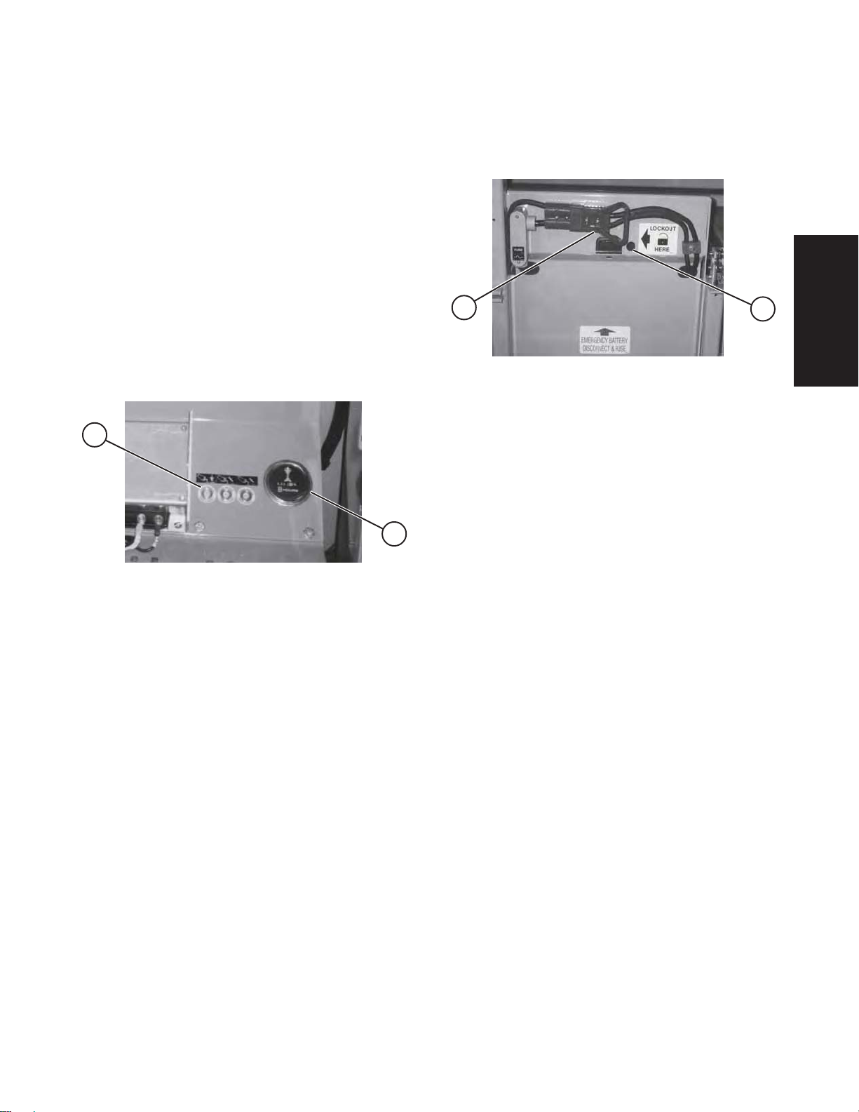
2
1
Figure 2-1. Electrical Panel
Emergency Battery Disconnect
1
Figure 2-2. Emergency Battery Disconnect Switch
1- Emergency Battery Disconnect Switch -
Located at the front of the Pull-Out Battery Tray, these
connectors when separated, disconnect the batteries
and all power to the platform and base control
stations. In the event of an emergency or when
performing maintenance, grasp the handle and pull
the connectors apart.
2- Battery Lockout - This lockout is provided to
prevent unauthorized use and for maintenance
purposes.
2
2
Electrical Panel
This control station is located in the Hydraulic/Electric
side cabinet. It contains the following controls:
1- Hourmeter - Activated when a function is selected,
this gauge records work platform operating time.
2- 20 Amp Circuit Breaker Resets - In the event of
a power overload or positive circuit grounding, circuit
breaker will pop out. Make the necessary corrections,
then depress the push-button to reset.
SJ-800E Series Battery Powered
117131AH
SECTION 2, Page 13
Mar . 2002
Page 13
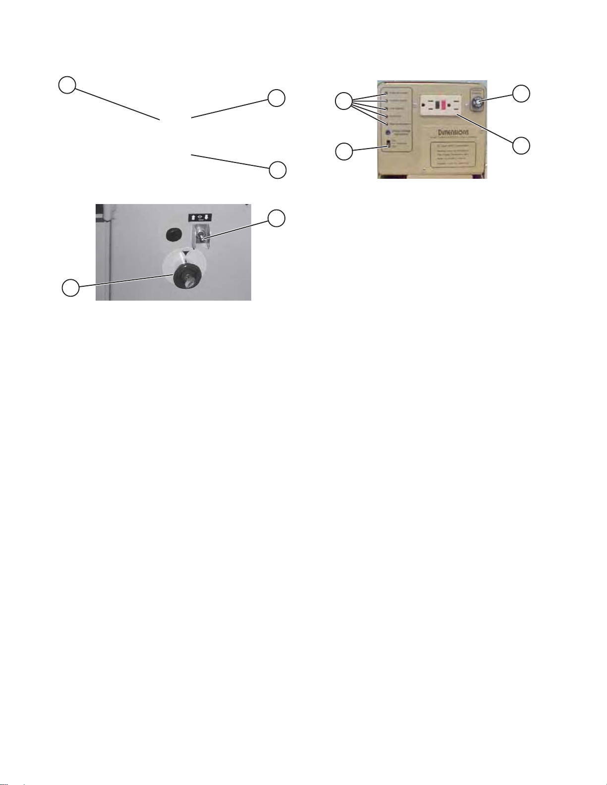
Base Control Station
1500W AC Inverter (Option)
3
1
2
Figure 2-3A. Base Control Station (ANSI & CSA)
1
2
Figure 2-3B Base Control Station (CE)
Base Control Station
This metal control station is mounted on the rear of
the hydraulic/electric side cabinet. It contains the
following controls:
1- Platform Up/Down Toggle Switch - This toggle
type switch raises or lowers the platform to a desired
height.
2
1
Figure 2-4. 1500W AC Inverter
Inverter - The inverter is located on the base of the
machine, it has the following controls.
1. ON/OFF Switch - This slide switch will activate or
terminates inverter function.
2. Status LEDs - These LEDs indicate the operating
or fault status of the inverter .
3. 15 Amp Circuit Breaker - In the event of a power
overload or circuit grounding, this circuit breaker will
pop out.
4. GFCI Outlet - During inverter operation, this outlet
provides AC power.
3
4
2- Emergency Stop Button - This red “mushroomhead” shaped button switch is designed to disengage
power to both the platform and base controls.
3- Base/Platform Toggle Switch (ANSI & CSA) When “BASE” position is selected and held, power is
directed to the Base Control Station. NOTE: This
switch is maintained in the “PLATFORM” position.
SECTION 2, Page 14
Mar . 2002
SJ-800E Series Battery Powered
117131AH
Page 14
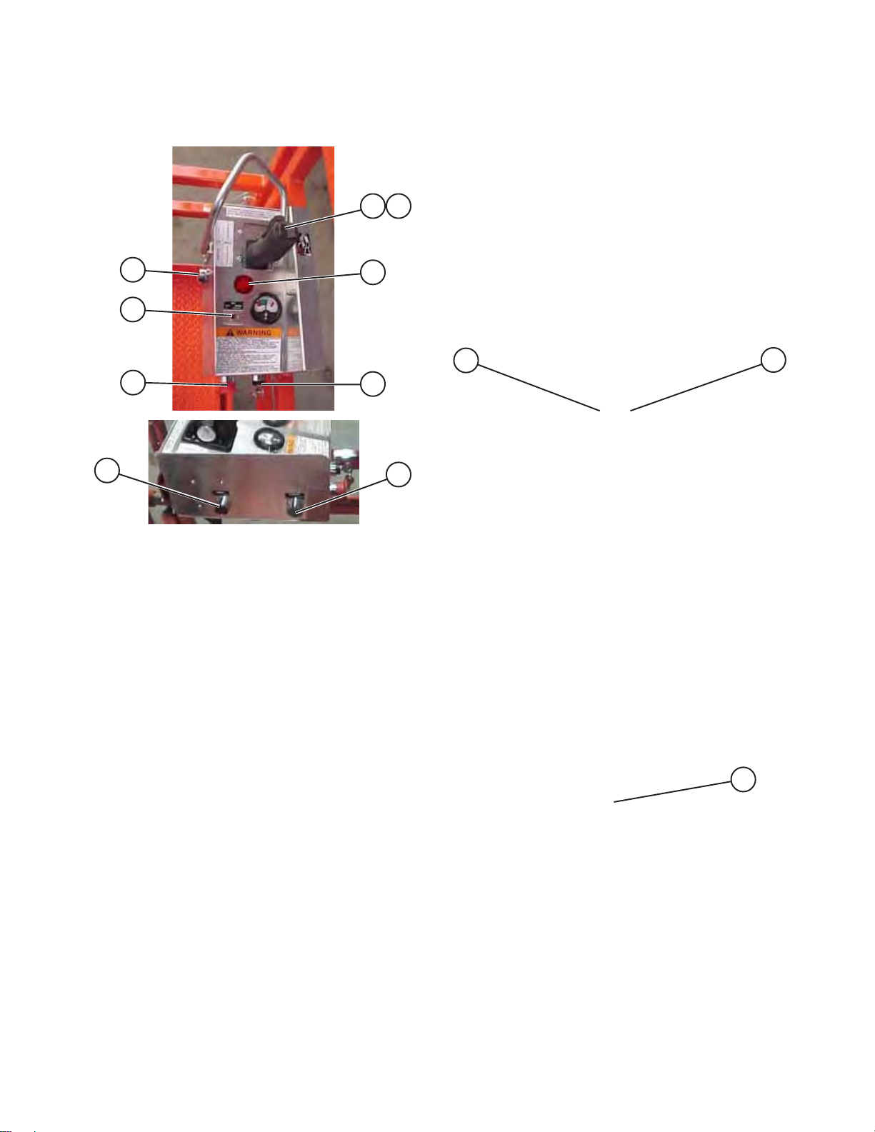
Platform Controls
Operator’s Control Box
7
1 2
3
6- Lift/Off/Drive Select Toggle Switch - If “Lift” is
selected, the lift circuit is energized. “OFF”
disconnects power from both the lift and drive circuits.
If “DRIVE” is selected, the drive circuit is energized.
7- Operator Horn Push-Button - This momentary
push-button switch activates an automotive-type horn.
8- Lift/Drive Enable Push-Button (Earlier Models)
- This momentary push-button switch energizes the
lever controller. It must be held depressed while
engaging either the lift or drive functions.
6
5
7
Figure 2-5 Operator’s Control Box
Operator’s Control Box
This metal control station is mounted at the right front
of the platform. It contains the following controls:
1- Lift/Drive Function Controller - A one-hand
toggle-type lever to control drive/lift motion and steer
motion. It is a “deadman” control which returns to
neutral when released.
4
8
Powered Extension Platform Control Box
1
Figure 2-6. Powered Extension Control Box
Powered Extension Platform Control Box
1- Enable Switch - This switch, when activated,
brings power to the Platform Extend/Retract Selector
Switch.
2- Platform Extend/Retract Selector Switch - This
switch, when activated, extends or retracts the
platform.
2
2- Lift/Drive Enable Switch - This momentary
“Trigger” style switch (on later models) energizes the
proportional controller. It must be held depressed
continuously while engaging either the drive/lift or
steer functions.
3- Warning Alarm Indictor Light - Light will glow and
an alarm will sound when an unsafe condition occurs.
4- Platform/Off/Base Select Key Switch (CE) - This
three-way selector switch allows the operator to turn
off the power to the unit or to activate either the base
or platform controls.
5- Emergency Stop Button - This red “mushroomhead” shaped button switch is designed to disengage
power to the platform controls.
SJ-800E Series Battery Powered
117131AH
Mar . 2002
Outrigger Control Box
1
Figure 2-7. Outrigger Control Box
Outrigger Control Box
This metal box, adjacent to the Operator’s Control
Box, contains toggle switches to control each
outrigger’s extension and retraction.
1- Outrigger Up/Down Control Toggle Switches This switch, when activated, extends or retracts
individual outriggers.
SECTION 2, Page 15
Page 15
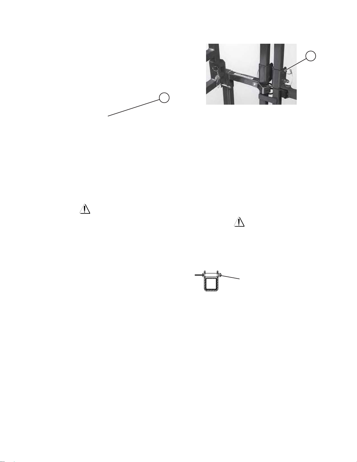
Identification And Operation Of
Safety Devices
Manual Safety Bar
1
Figure 2-8. Safety Bar
1. Safety Bar - Designed to support the scissors
assembly (when properly positioned), the safety bar
MUST be used for inspection and performing
maintenance or repairs within the scissors assembly.
To lower safety bar, push lock lever rearward and the
safety bar will drop. Follow procedure on safety bar
decal to properly position safety bar.
Warning
Fold-Down Guardrail System
1
Figure 2-9. Fold-Down Guardrail System
Fold-Down Guardrail System
This system when folded down, reduces the shut
height of the work platform for transporting and
travelling through doorways.
1- Guardrail Locking Pin With Lanyard - To fold the
guardrail system down, remove the locking pin at
each pivot point and lower each guardrail. To raise
the guardrail system, swing up each guardrail and
lock in place with the locking pins ensuring that the
detent ball of each pin is clear of the side of the pivot
brackets. (Figure 2-10.)
Crushing Hazard
DO NOT reach through the scissor assembly when
the platform is raised without the safety bar properly
positioned. Lower the platform until the scissor assembly is firmly supported by the safety bar. Failure
to avoid this hazard will result in death or serious
injury!
Warning Alarm And Indictor Light
Light Indicator on control box (Figure 2-5) will glow
and an alarm will sound when an unsafe condition
occurs. Examples are:
1. Machine is in a tilted position.
2. Outriggers are out of a set position. (Not Fully
extended or retracted.) (if equipped)
3. Platform is overloaded. (If equipped with an
overload pressure switch.)
Correct the unsafe condition to resume normal
operation.
Warning
The guardrail system MUST be upright and locked in
place before resuming normal operation. Check the
guardrail system for loose or missing locking pins
before operating this equipment!
DETENT BALL CLEAR OF
SIDE OF PIVOT BRACKET
Figure 2-10. Correct Position of Locking Pin
SECTION 2, Page 16
Mar . 2002
SJ-800E Series Battery Powered
117131AH
Page 16

Operator Qualifications
Warning
Only trained and authorized persons should use this
work platform. Safe use of this work platform requires
the operator to understand the limitations and
warnings, operating procedures and operator’s
responsibility for maintenance. Accordingly, the
operator MUST understand and be familiar with this
operating manual, its warnings and instructions and
ALL warnings and instructions on the work platform.
Operator also MUST be familiar with employer’s work
rules and related government regulations and be able
to demonstrate his/her ability to understand and
operate THIS make and model work platform in the
presence of a qualified person.
Operating Procedures
The following descriptions are for Operating
Procedures. A qualified operator MUST read and
completely understand these descriptions before
operating this work platform.
Set-Up Procedure
1. Remove all packing materials and inspect for
damage incurred during transport. This is
normally required for equipment being put into
service for the first time, after the equipment
has been unloaded.
Note
Report any damage to delivery carrier immediately.
2. Inspect work platform thoroughly and remove
any foreign objects.
Explosion Hazard
Keep flames and sparks away. DO NOT smoke near
batteries.
First Aid
Immediately flush eyes with cold water if electrolytic acid
is splattered into them. Seek medical attention if
discomfort continues.
5. Unlock and roll out the battery tray. In the battery
tray, check the electrolyte level in all eight
batteries. If plates are not covered, carefully add
distilled or demineralized water . If needed, check
the specific gravity in each battery, it should be
1.260 to 1.275. (This reading will not be correct
if you just added water to the batteries.)
6. Connect the A.C. battery charger cord to the
proper A.C. voltage source and charge the
batteries. (Refer to “Battery Charging
Procedures”).
7. When charger cycle is complete, disconnect the
battery charger A.C. cord and return the battery
tray to the locked closed position. Ensure that
the Emergency Battery Disconnect is properly
connected and all the Emergency Stop Switches
are pulled out.
8. In the hydraulic/electric cabinet, check the
hydraulic oil level (scissors MUST be fully
lowered) in the tank. Level should be at or
slightly above the top mark on the gauge. If
required, add a quality grade hydraulic oil such
as ATF Dextron III (ESSO). Refer to the
“HYDRAULIC OIL” label located on the oil
reservoir for specific applications.
3. Raise the side, extension platform (if so
equipped), and gate railings to their upright
position and lock in place with locking pins.
Lock side railings to front railings with locking
pins. (Refer to Figure 2-10.).
4. Remove the operator’s control box from its
shipping container and secure it to the railing
at the right front of the platform. Attach the
control cable and power deck extension cable
(if so equipped) to the scissor’s control cable.
SJ-800E Series Battery Powered
117131AH
Mar . 2002
10A. On (CE) machines:
Raise the platform, by selecting “BASE” position,
with the Platform/Off/Base Select Switch (Figure
2-5.), then from the base control station, push
the base Up/Down Toggle Switch to the “
position until there is an adequate clearance to
swing down and position the safety bar.
10B. On ANSI/SIA and CSA machines:
Raise the platform from the base control station
by pushing the “Base/Platform” switch to the
“base” position while pressing the base Up/Down
Toggle Switch to the “
is an adequate clearance to swing down and
position the safety bar.
××
×” (up) position until there
××
SECTION 2, Page 17
××
×” (up)
××
Page 17

11. Release the Safety Bar from it’s storage location
and swing down into position. (Refer to label on
base for proper procedure.) Lower the platform
until the scissor assembly is firmly supported
by the safety bar.
3. Check overhead clearances.
4. Make sure the batteries are fully charged.
Disconnect the AC charger cord from the
external power source.
12. Inspect all hoses, fittings, wires, cables, valves,
etc. for leaks, hidden damage and foreign
material.
13A. On (CE) machines:
Raise the platform, by selecting “BASE” position,
with the Platform/Off/Base Select Switch (Figure
2-5.), then from the base control station, push
the base Up/Down Toggle Switch to the “
position until there is an adequate clearance to
swing up the safety bar. Return the safety bar to
the locked storage position
13B. On ANSI/SIA and CSA machines:
Raise the platform from the base control station
by pushing the “Base/Platform” switch to the
“base” position while pressing the base “Up/
Down Toggle Switch” to the “
until there is an adequate clearance to swing up
the safety bar . Return the safety bar to the locked
storage position.
14. Raise the platform to the maximum extension
height.
××
×” (up) position
××
××
×” (up)
××
Note
Refer to Table 1-1. General Specifications (Section 1)
for raise and lowering times.
15. Fully lower the platform.
16. The SJ800E Series Work Platform is now ready
for use by an authorized, qualified operator who
has read and completely understands ALL of
Section 2, OPERATION in this manual.
5. Make sure all guardrails and lockpins are in
place and locked in position
6. Make sure the battery tray and all cabinet doors
are closed.
7. Make sure you do not climb or descend a
grade steeper than 25%. Elevated driving
must only be done on firm level surfaces.
OPERATOR’S CHECKLIST
INSPECT AND/OR TEST THE FOLLOWING
DAILY OR A T BEGINNING OF EACH SHIFT
1 OPERATING AND EMERGENCY CONTROLS.
2 SAFETY DEVICES AND LIMIT SWITCHES.
3 PERSONAL PROTECTIVE DEVICES.
4 TIRES AND WHEELS.
5 OUTRIGGERS (IF EQUIPPED) AND OTHER
STRUCTURES.
6 AIR, HYDRAULIC AND FUEL SYSTEM(S) FOR
LEAKS.
7 LOOSE OR MISSING PARTS.
8 CABLES AND WIRING HARNESSES.
9 PLACARDS, WARNINGS, CONTROL MARKINGS
AND OPERATING MANUALS.
10 GUARDRAIL SYSTEM INCLUDING LOCKING PINS.
11 ENGINE OIL LEVEL (IF SO EQUIPPED).
12 BATTERY FLUID LEVEL.
13 HYDRAULIC RESERVOIR LEVEL.
14 COOLANT LEVEL (IF SO EQUIPPED).
Warning
Prestart Checks
1. Carefully read and completely understand ALL
of Section 2, OPERATION in this manual and
ALL warnings and instruction labels on the work
platform.
2. Ensure that there are no obstacles around the
work platform and in the path of travel such as
holes, drop offs, ditches, soft fill or debris.
SECTION 2, Page 18
Mar . 2002
DO NOT OPERATE THIS EQUIPMENT WITHOUT
PROPER AUTHORIZATION AND TRAINING.
DEATH OR SERIOUS INJURY COULD RESULT
FROM IMPROPER USE OF THIS EQUIPMENT!
SJ-800E Series Battery Powered
117131AH
Page 18

Start and Operation
Using the controls on the base:
1. Ensure that the Emergency Battery Disconnect
is properly connected and the Emergency Stop
Switch is pulled out.
7. To Drive Forward or Reverse: Select “DRIVE”
position with the Lift/Off/Drive Toggle Switch.
Depress and hold the Enable push-button, then
lift the controller lock ring and push the controller
handle forward or backwards. Release handle
to stop.
2. Use the ladder at the either side of the work
platform to access the work platform deck.
3. Latch the entry gate.
Using the controls on the platform:
4. Pull out the Emergency Stop Button.
5. Turn key switch to “PLATFORM” position.
6. To Raise or Lower the Platform: Select “LIF T”
position with the Lift/Off/Drive Toggle Switch.
Depress and hold the Enable push-button, then
lift the controller lock ring and push the controller
handle forward to raise or backwards to lower
until a desired height is reached. Release handle
to stop.
Note: Platform lowering is not proportional.
Note
If the tilt alarm sounds and the platform does not, or
only partially raises, immediately lower the platform
and ensure that the machine is on a compacted
LEVEL surface.
Warning
IF THE MACHINE DOES NOT DRIVE WHEN
ELEVATED, DISENGAGE THE DRIVE
CONTROLLER. LOWER THE PLATFORM
IMMEDIATELY. ENSURE THE MACHINE IS
BEING OPERATED ON A COMPACTED, FIRM
LEVEL SURFACE OR THE TILT SENSOR WILL
DISABLE SOME OR ALL FUNCTIONS.
8. To Sound the Horn: Depress the horn push-
button located on the side of the operator’s
platform control box.
9. To Steer: Select “DRIVE” position with the Lift/
Off/Drive Toggle Switch. Depress and hold the
Enable push-button, then press the rocker on
top of the controller handle in the direction you
wish to steer.
Note: Steering is not proportional.
10. To Extend/Retract the Manual Extension
Platform: Remove the locking pin(s) and push/
pull the extension deck using the push-bar.
Reinsert the locking pin(s) to prevent accidental
movement of the extension platform.
Warning
TO PROTECT AGAINST UNINTENDED
MOVEMENT OF THE WORK PLATFORM, PUSH
IN THE EMERGENCY STOP BUTTON AFTER YOU
HAVE ARRIVED AT YOUR DESIRED LOCATION
OR ELEVA TION.
SJ-800E Series Battery Powered
117131AH
Mar . 2002
11. To Extend/Retract the Powered Extension
Platform: To extend the platform, select “LIFT”
position with the Lift/Off/Drive Select Switch on
the main platform control box. Then, from the
extension platform control box, activate the
“Enable” switch while toggling the extend/retract
switch to “
extension is reached. Release the switch to stop.
To retract the platform, select “LIFT” position with
the Lift/Off/Drive Select Switch on the main
platform control box. Then, from the extension
platform control box, activate the “Enable” switch
while toggling the extend/retract switch to “
(retract) position until desired retraction is
reached. Release the switch to stop.
××
× ” (extend) position until desired
××
ØØ
Ø”
ØØ
SECTION 2, Page 19
Page 19
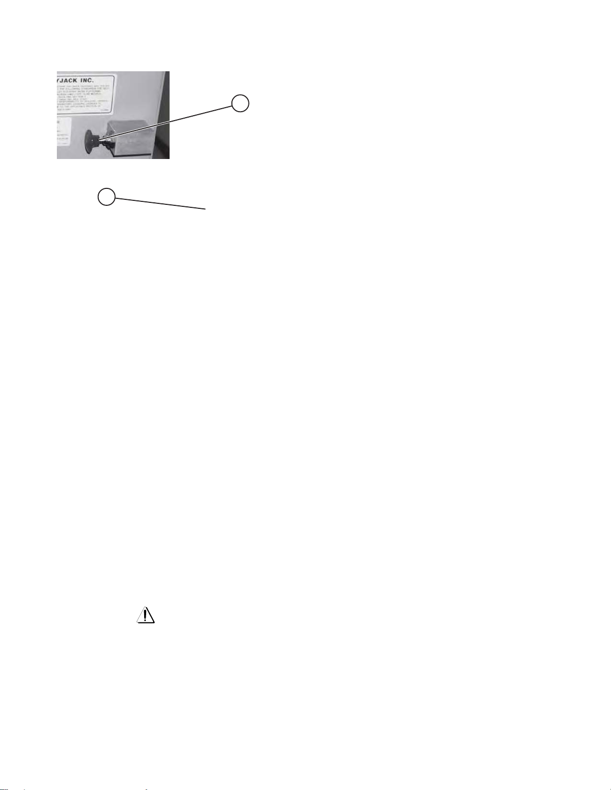
Emergency Lowering System
Shutdown Procedure
1. Fully lower the platform.
2
1
Figure 2-11. Emergency Lowering System
Emergency Lowering Valve and Holding Valve
Manual Override Knob
This system allows platform lowering in the event of
an electrical system failure. Use the following procedure to lower the platform:
1. Holding Valve Manual Override Knob - Located
on the holding valve at the bottom of each lift cylinder,
these red knurled knobs when depressed and turned
counter-clockwise allow hydraulic oil to bypass each
holding valve. The red knurled knobs on each
holding valve MUST be depressed and turned
clockwise to restore normal operation. A rod for
elevated manual override knob rotation shall be
provided for CE units only.
2. Turn Key Switch to “OFF” position. Remove key.
3. Push in Emergency Stop Button.
4. Push in Emergency Stop Button located on
Base and remove key. It is not necessary to
separate the Emergency Battery Disconnect
connectors at work platform shutdown
2. Emergency Lowering Valve - Pull out and hold
the Emergency Lowering Valve plunger, and the
platform will gradually lower. Located at the rear of
the hydraulic/electric side cabinet, this pull-type valve
when used in conjunction with the holding valve
manual overrides, allows platform lowering in the
event of an emergency or electrical system failure.
Activate all holding valve manual override knobs,
then pull and hold the plunger out to lower platform.
Release to stop.
Warning
Crushing Hazard
Keep clear of scissors mechanism when using
emergency lowering valve! After emergency
lowering is completed, the red knurled knobs on
each holding valve MUST be depressed and turned
clockwise to restore normal operation.
SECTION 2, Page 20
Mar . 2002
SJ-800E Series Battery Powered
117131AH
Page 20
Winching and Towing Procedures
Warning
Warning
DO NOT manually disengage the parking brakes if
the work platform is on a slope.
When Towing, DO NOT drive onto a downward slope
or brake the towing vehicle rapidly.
Preparation for Winching Or Towing
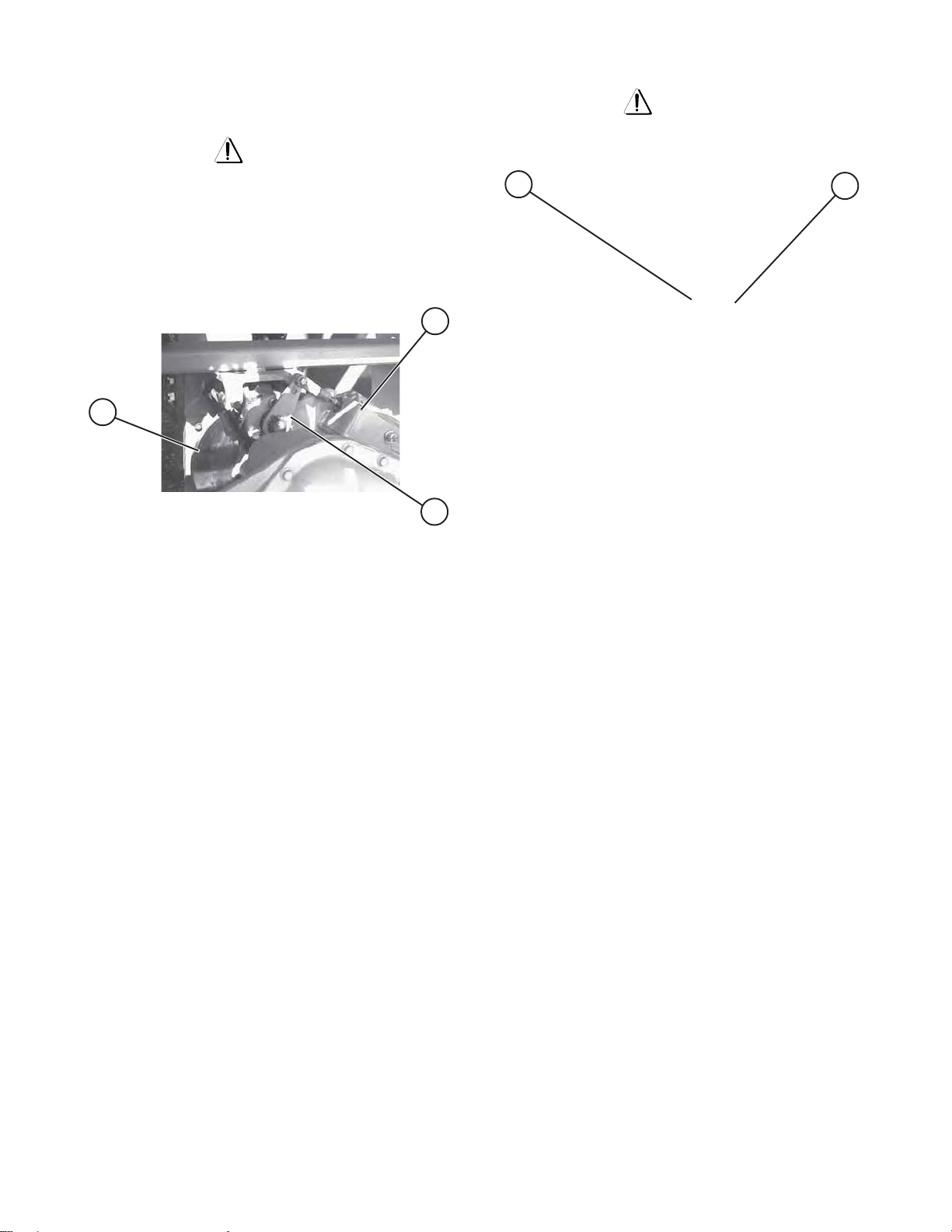
Parking Brake System
2
1
3
Figure 2-12. Disc Parking Brake
1 - 3. Parking Brake Disc -This device disengages
the brake disc(1) when driving forward or in reverse.
A hydraulic brake cylinder(2), linked to a disc
caliper(3), engages and disengages a brake disc on
the rear axle drive shaft yoke. The brake MUST be
manually disengaged for pushing, towing or
winching. DO NOT push or tow the work platform
onto a downward slope or pull the platform down
an incline towards the winch. The special procedure
for manually disengaging the parking brake is as
follows:
4
Figure 2-13. Parking Brake Release Hand Pump and
Brake Valve Plunger
4 - 5. Parking Brake Release Hand Pump(4) and
Brake Valve Plunger(5) - Located on the brake
manifold in the hydraulic electric side cabinet, this
hand operated pump MUST be used when pushing,
towing or winching the work platform. To release the
parking brake:
1. Make sure that the work platform is on level
ground. Chock or block the wheels to keep
work platform from rolling.
2. Turn Emergency Power Disconnect Switch to
“OFF” position.
3. Depress the black plunger on the Brake Valve
until the plunger stays in.
4. Grasp the red hand pump plunger and rapidly
depress 60 to 80 times until firm resistance is
felt. The brake is now released.
5
SJ-800E Series Battery Powered
117131AH
5. Remove the wheel chocks or blocks, then push,
6. Position machine on a firm and level surface.
The parking brake will reset automatically when the work
platform is put back into service.
Mar . 2002
tow or winch the work platform to the desired
location. When pushing, towing or winching,
DO NOT exceed 2 mph (3.2 km/h).
push or tow the platform onto a downward
slope or pull the platform down an incline
towards the winch.
Chock or block the wheels to prevent the
platform from rolling or re-engage the parking
brake by momentarily activating the drive function.
DO NOT
Note
SECTION 2, Page 21
Page 21

Outrigger Operating Procedures
(Machines with Outrigger Option)
Before Operation
1. Check overhead clearances and ground
obstructions. This will require the operator to
move around the platform.
NOTE:
If the platform will not lift and alarm sounds (if
equipped), MACHINE IS NOT LEVEL or outriggers
are not properly set! Make necessary adjustments
to level machine!)
Operation - Retracting The Outriggers
2. Check that the supporting surface under the tires
and outrigger pads is firm and stable. DO NOT
place outrigger pad on a street drain or manhole
cover. The operator is responsible for deciding
whether blocking (such as timbers) is needed.
3. Check that the platform is fully lowered. (The
outrigger controls are cut out when the platform
is raised.)
Operation - Extending The Outriggers
1. From the operator’s platform control box, select
“PLATFORM” with the BASE/OFF/PLATFORM”
keyswitch. Select the “LIFT” position with the
“LIFT/OFF/DRIVE” toggle switch.
2. P ush and hold each Outrigger Up/Down Toggle
Switch to “DOWN” position extending each of
the outriggers to obtain firm ground contact.
3. Check outrigger pad contact surface! Make
adjustments as necessary.
4. Again, push and hold each Outrigger Up/Down
Toggle Switch to “DOWN” position extending
each of the outriggers until the machine is
completely supported by the outriggers.
1. Fully lower the platform:
1- Ensure the emergency stop button is pulled
out. Select “LIFT” position with the Lift/Off/
Drive Toggle Switch.
2- Earlier models: Depress and hold the
Enable push-button (if equipped), then lift
the controller lock ring.
Later models: Activate and hold the Enable
trigger switch (by squeezing it towards the
joystick)
3- Pull the controller handle backward until the
platform is fully lowered.
4- Return the joystick to the neutral center
position to stop. Release the Enable switch
(if equipped).
2. Push and hold pairs (front or rear) of Outrigger
Up/Down Toggle Switches to “UP” position until
the outriggers are fully retracted.
Note
Switches are used to protect the outriggers from being
damaged. If machine will not drive, visually check to
see that ALL outriggers are fully retracted.
During Operation
5. Level the machine. AGAIN, CHECK THE
OUTRIGGER PAD CONTACT SURFACE!
6. Raise the Platform:
1- Ensure the emergency stop button is pulled
out. Select “LIFT” position with the Lift/Off/
Drive Toggle Switch.
2- Earlier models: Depress and hold the
Enable push-button (if equipped), then lift
the controller lock ring.
Later models: Activate and hold the Enable
trigger switch (by squeezing it towards the
joystick)
3- Push the controller handle forward to raise
the platform until a desired height is reached.
4- Return the joystick to the neutral center
position to stop. Release the Enable switch
(if equipped).
SECTION 2, Page 22
Mar . 2002
1. Check the level of the machine frequently by
lowering the platform slightly and then attempt
to raise the platform. If alarm sounds (if
equipped), LOWER THE PLATFORM
IMMEDIATELY! Make the necessary
adjustments to level the machine!
SJ-800E Series Battery Powered
117131AH
Page 22

Electrical Inverter (Option)
1. Turn the main disconnect switch to the “ON”
position.
2. Turn the “ON/OFF” switch located on the front
face of the inverter to the “ON” position.
Battery Service And Charging
Procedures
Battery Service
Warning
Explosion Hazard
3. Pull out the “EMERGENCY STOP” switch located
on the operator’s control box, to the closed
position.
4. Inverter activation is indicated by a glowing green
LED on the front face of the inverter.
5. To turn off the inverter, push in the “EMERGENCY
STOP” switch located on the operator’s control
box to the open position, or slide the “ON/OFF”
switch located on the front face of the inverter to
the “OFF” position.
Note
When the work is not in use, the “EMERGENCY
STOP” switch located on the operator’s control box
should be pushed to it’s opened position. This will
turn off the inverter.
Keep flames and sparks away. DO NOT smoke near
batteries.
Caution
Contact with electrolytic acid can cause skin irritation
and damage clothing. Wear a protective apron, gloves
and goggles when working with batteries.
First Aid
Immediately flush eyes with cold water if electrolytic
acid is splattered into them. Seek medical attention if
discomfort continues.
Servicing the Batteries
1. Separate the Emergency Battery D isconnect
connectors.
2. Check battery case for damage.
3. Check battery fluid level in each battery. If plates
are not covered by at least 1/2” (13mm) of
solution, add distilled or demineralized water.
SJ-800E Series Battery Powered
117131AH
4. Clean battery terminals and cable ends
thoroughly with a terminal cleaning tool or wire
brush.
5. Make sure all battery connections are tight.
6. Replace any battery that is damaged or incapable
of holding a lasting charge.
7. Do not use any batteries other than flooded leadacid batteries of the proper AH rating.
Battery Charging Procedures
Warning
Explosion Hazard
Chargers can ignite flammable materials and vapors.
DO NOT use near fuels, grain dust, solvents or other
flammable
SECTION 2, Page 23
Mar . 2002
Page 23
Warning
Shock Hazard
Battery Charger Operation
Bycan Charger
To reduce the risk of electrical shock, the charger
must only be connected to properly grounded single
phase outlet. If charging using 120V, each charger
must be plugged into a separate circuit Also, each
AC circuit protection should not exceed 15 amperes.
The extension cord used must be a three wire
grounded cord of at least 14 AWG. DO NOT use an
extension cord longer than 25 feet (7.6m). Inspect
AC charger’s receptacle for the presence of water from
washing or storage. Dry thoroughly prior to use.
NOTE
For standard machines, the Emergency Disconnect
connectors MUST be closed (connected) to charge the
batteries. For EE rated machines, use the battery
bank’s emergency disconnect connector for charging.
1. Check for a firm AC connection at the charger
receptacle. Connect the charger cord to the AC
wall plug to turn the charger on. Refer to charger
nameplate for voltage requirements.
2. Charge batteries. DO NOT leave charger
unattended for more than two consecutive days.
Severe overcharging and battery damage will
result if charger fails to turn off.
1
2
3
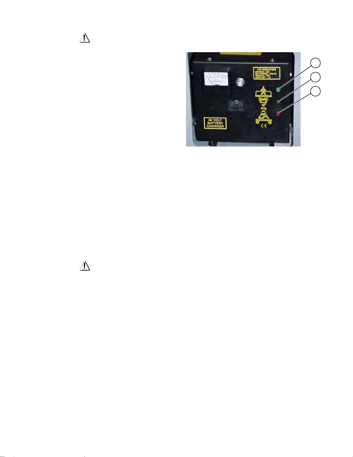
Figure 2-14. Bycan Battery Charger
(SK4825U Shown)
1 Green LED
2 Yellow LED
3 Red LED
Battery Status (SK4825U)
Red LED . ..................................................... Charging
Red/Yellow LED ..................................... 80% Charged
Green LED .................................................... Complete
Yellow LED............................................ Check Battery
3. Disconnect charger from external power source.
Warning
DO NOT CHARGE BATTERIES IN HAZARDOUS
AREA! THE EE-RATING OF A MACHINE DOES
NOT INCLUDE THE CHARGING OF BATTERIES.
Battery Charging Procedures
(EE-Rated Machines)
1. Move the work platform to an area designated
for battery charging. (Refer to NFPA 505* for
charging set-up.) *NFPA 505 is a publication of:
National Fire Protection Association, Inc.
Batterymarch Park, Quincy, MA 02269 (USA)
2. Connect the battery charger’s plug into the
battery main disconnect plug, at the front of the
base.
Apply The AC power. The charger will start immediately (the transformer will hum and fan will come on).
The red LED will come on. The ammeter will show
charging current.
The current will be high for approximately 30 minutes
then it will taper off. If the current does not taper off,
disconnect the charger and check the batteries for a
shorted cell.
When the battery bank voltage reaches approximately
59 volts DC, the yellow flashing LED will illuminate.
This indicates that the charger has now entered a
timed equalizing cycle. After completing the 3.5 hour
cycle, the charger will shut off and the green LED will
come on to indicate a complete charge.
If a shorted battery cell prevents the charger from raising the battery voltage to approximately 59 VDC to
start the equalization timer, a second timer will shut
down the charger after 16 hours of continuous charging. When this happens, the flashing yellow LED will
come on to notify the user that the battery bank should
be inspected for a shorted/damaged cell.
SECTION 2, Page 24
Mar . 2002
SJ-800E Series Battery Powered
117131AH
Page 24
MAC Charger Operation (#BA1045)
1
2
3
4
5
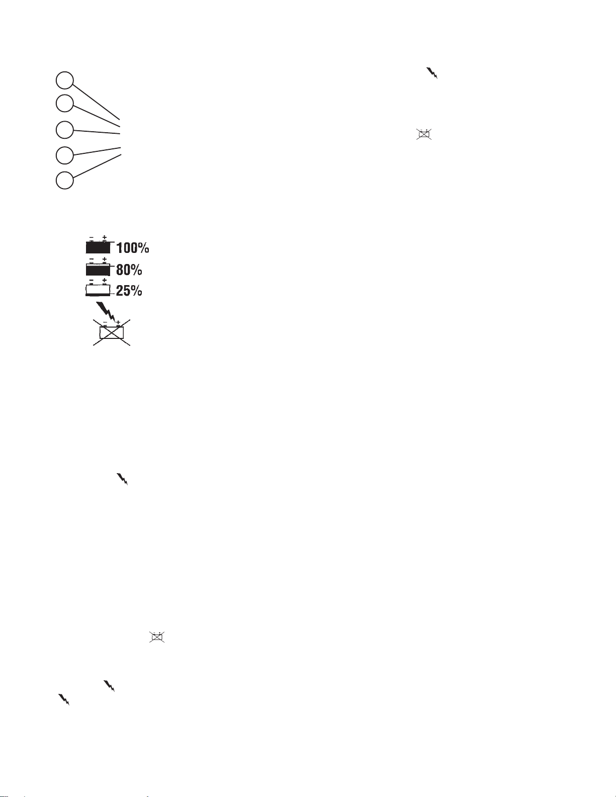
Figure 2-15. Automatic SCR Battery Charger
If the charger is restarted on a fully charged battery
pack, the 80% and the “ ” (CHARGER ON) lights will
illuminate for approximately 70 minutes. After 70
minutes, the 100% (COMPLETE) light will be
illuminated. The charger has a 20 hour timer. If the
batteries do not reach approximately 2.55 volts per
cell in 20 hours, the “ ” (ABNORMAL) and the 80%
lights will be illuminated. To restart the charger,
disconnect then reconnect the AC power cord and
another 20 hour charging cycle will begin.
This charger has an automatic circuit that allows
operation at any input voltage and either 50Hz or
60Hz.
1.
2.
3.
4.
5.
This charger is equipped with an electronic circuit
that will completely recharge the batteries and
automatically turn off after the charge cycle is
complete.
The function of the L.E.D. indicators is as follows:
When both AC and DC connections are made, the
LED display will flash 3 times and will flash each LED
in sequence. After approximately 5 seconds, the 25%
light and the “ ” (CHARGER ON) light will illuminate.
This signifies that the charging current is flowing into
the batteries and the charger is charging normally.
The 80% light will illuminate and the 25%
(INCOMPLETE) light will shut off when the batteries
reach the gassing point 2.37 volts per cell. The 80%
light will continue to be illuminated until the batteries
reach approximately 2.55 volts per cell. At this time,
the 100% (COMPLETE) light will be the only LED that
is illuminated.
Green (COMPLETE)
Green (80% COMPLETE)
Green (INCOMPLETE)
Yellow (CHARGER ON)
Yellow (ABNORMAL)
Refer to “Battery Service And Charging Procedures”
for proper battery inspection and maintenance
procedures.
If during the charging cycle AC power is interrupted
to the charger, the “ ” (ABNORMAL) and the 25%
light will be illuminated. When AC power is restored,
the charger will resume the charge cycle and no light
sequencing will occur. The display will resume with
either the “ ” (CHARGER ON) and 25% lights or the
“ ” (CHARGER ON) and 80% lights depending on
the batteries level of charge.
SJ-800E Series Battery Powered
117131AH
SECTION 2, Page 25
Mar . 2002
Page 25

MAC Charger Operation (#BA1001)
1
6
If the “80% CHARGE” light continues to stay on after
7
the charge cycle is complete, this indicates to the
operator that the batteries are not capable of attaining
a full charge.
2
3
4
5
Figure 2-16. Automatic Battery Charger
BATTERY STATUS
1. GREEN LED .....................CHARGE COMPLETE
2. YELLOW LED ................................80% CHARGE
3. RED LED .......................................INCOMPLETE
CHARGER STATUS
4. YELLOW LED ............................... CHARGER ON
5. RED LED ............................. ABNORMAL CYCLE
6. CHARGER STOP SWITCH
7. FUSE HOLDER
If the “INCOMPLETE” light remains on after the charge
cycle is complete, this indicates to the operator that
the batteries are not capable of attaining even an 80%
charge.
If either the “80% CHARGE” or “INCOMPLETE” light
remain on after the charge cycle is complete, the
batteries should be inspected for problems.
Your standard good watering procedures should be
used at all times.
This charger is equipped with an electronic circuit
that will completely recharge the batteries and
automatically turn off after the charge cycle is
complete.
The function of the LED indicators is as follows:
When the AC power is connected to the charger, the
LED’s will flash several times then flash independently
to check the light circuits. After the flashing sequence
is complete the “INCOMPLETE” light will come on.
Five seconds later , the “CHARGER ON” light will come
on and at the same time, the ammeter will indicate
how much current is going to the batteries.
As the charge cycle continues, which can last between
1-1/2 hours and 16 hours for a complete cycle,
depending on the state of charge of the batteries, the
“80% CHARGE” light will come on and the
“INCOMPLETE” light will go off. When voltage of the
batteries reaches approximately 60 volts, the “80%
CHARGE” light will go off and the “CHARGE
COMPLETE” light will come on. This light will remain
on even after the charger is turned off by the electronic
control. After the charger turns off, the “CHARGE
COMPLETE” light will indicate to the operator that
the batteries are healthy and are fully charged.
SECTION 2, Page 26
Mar . 2002
SJ-800E Series Battery Powered
117131AH
Page 26
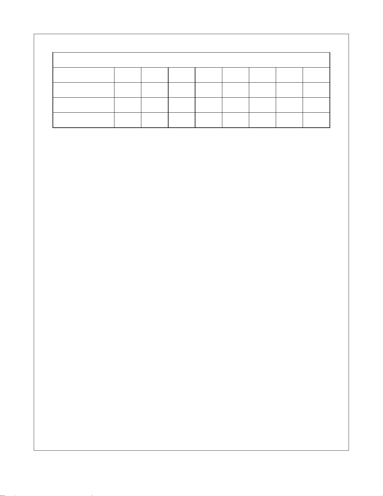
Table 2-1. Owner’s Annual Inspection Record
MODEL NUMBER________________________________ SERIAL NUMBER________________________
RECORDING
DATE
RECORDING
YEAR #
OWNER’S
NAME
INSPECTED
BY
12345678
SJ-800E Series Battery Powered
117131AH
SECTION 2, Page 27
Mar . 2002
Page 27
Table 2-2A. Maximum Platform Capacities (800E Series) (Evenly Distributed)
Manufactured before January 2000. “Meets ANSI/SIA-A92.6 - 1990 Standard”
MODEL
No extension
Platform
One Extension
Platform
8831E
Two Extension
Platforms
No extension
Platform
One Extension
Platform
8831FE
Two Extension
Platforms
No extension
Platform
One Extension
Platform
8841E
Two Extension
Platforms
No extension
Platform
One Extension
Platform
8841FE
Two Extension
Platforms
Capacity
2500 lbs.
(1134 kg)
1500 lbs.
(680 kg)
500 lbs.
(227 kg)
2500 lbs.
(1134 kg)
1500 lbs.
(680 kg)
800 lbs.
(363 kg)
1500 lbs.
(680 kg)
1000 lbs.
(454 kg)
500 lbs.
(227 kg)
2000 lbs.
(907 kg)
1200 lbs.
(544 kg)
700 lbs.
(317 kg)
Main
Platform
Number Of
Occupants
First
Extension
Capacity
6----
4
2
6----
4
2
6----
4
2
6----
4
2
500 lbs.
(227 kg)
500 lbs.
(227 kg)
500 lbs.
(227 kg)
500 lbs.
(227 kg)
500 lbs.
(227 kg)
500 lbs.
(227 kg)
500 lbs.
(227 kg)
500 lbs.
(227 kg)
Number Of
Occupants
2--
2
2--
2
2--
2
2--
2
Capacity
500 lbs.
(227 kg)
500 lbs.
(227 kg)
500 lbs.
(227 kg)
500 lbs.
(227 kg)
Second
Extension
Number Of
Occupants
Platform
Capacity
2500 lbs.
(1134 kg)
2000 lbs.
(907 kg)
2
2
2
2
1500 lbs.
(680 kg)
2500 lbs.
(1134 kg)
2000 lbs.
(907 kg)
1800 lbs.
(817 kg)
1500 lbs.
(680 kg)
1500 lbs.
(680 kg)
1500 lbs.
(680 kg)
2000 lbs.
(907 kg)
1700 lbs.
(771 kg)
1700 lbs.
(771 kg)
Total
NOTE: Occupants AND materials are not to exceed rated load.
Capacities listed are for standard machines equipped with #6 tires.
Refer to capacity label at sides of platform for additional information.
SECTION 2, Page 28
Mar . 2002
SJ-800E Series Battery Powered
117131AH
Page 28
Table 2-2B. Maximum Platform Capacities (800E Series) (Evenly Distributed)
Manufactured after January 2000. “Meets ANSI/SIA-A92.6 - 1999 Standard”
MODEL
No extension
Platform
One Extension
Platform
8831E
Two Extension
Platforms
No extension
Platform
One Extension
Platform
8831FE
Two Extension
Platforms
No extension
Platform
One Extension
Platform
8841E
Two Extension
Platforms
No extension
Platform
One Extension
Platform
8841FE
Two Extension
Platforms
Platform
Capacity
2500 lbs.
(1134 kg)
1500 lbs.
(680 kg)
500 lbs.
(227 kg)
2500 lbs.
(1134 kg)
1500 lbs.
(680 kg)
800 lbs.
(363 kg)
1500 lbs.
(680 kg)
750 lbs.*
(340 kg)
250 lbs.*
(113 kg)
2000 lbs.
(907 kg)
1000 lbs.**
(454 kg)
500 lbs.**
(227 kg)
Main
Number Of
Occupants
First
Extension
Capacity
6----
4
2
6----
4
2
5----
2
***
6----
3
***
500 lbs.
(227 kg)
500 lbs.
(227 kg)
500 lbs.
(227 kg)
500 lbs.
(227 kg)
500 lbs.
(227 kg)
500 lbs.
(227 kg)
500 lbs.
(227 kg)
500 lbs.
(227 kg)
Number Of
Occupants
2--
2
2--
2
2--
***
2--
***
Capacity
500 lbs.
(227 kg)
500 lbs.
(227 kg)
500 lbs.
(227 kg)
500 lbs.
(227 kg)
Second
Extension
Number Of
Occupants
2
2
***
***
Total
Platform
Capacity
2500 lbs.
(1134 kg)
2000 lbs.
(907 kg)
1500 lbs.
(680 kg)
2500 lbs.
(1134 kg)
2000 lbs.
(907 kg)
1800 lbs.
(817 kg)
1500 lbs.
(680 kg)
1250 lbs.*
(567 kg)
1250 lbs.*
(567 kg)
2000 lbs.
(907 kg)
1500 lbs.**
(680 kg)
1500 lbs.**
(680 kg)
NOTE: Occupants AND materials are not to exceed rated load.
Capacities listed are for standard machines equipped with #6 tires.
Refer to capacity label at sides of platform for additional information.
*-Capacity is increased by 250 lbs. (113 kg) for European and CSA applications.
**-Capacity is increased by 200 lbs. (91 kg) for European and CSA applications.
***-Occupant capacity is a maximum of 4 Persons with no more than 2 people on an extension.
SJ-800E Series Battery Powered
117131AH
SECTION 2, Page 29
Mar . 2002
Page 29

Table 2-3. Maintenance And Inspection Schedule
Daily Weekly Monthly 3 Months 6 Months 12 Months*
Mechanical
Structural damage/welds A
Parking brake B &E
Tires/wheels & fasteners A, B & C
Guides/ rollers & slider pads A, B & I
Railings & railing lock pin s A & C
Entry gates B & C
Bolts and fasteners C
Safety Bar B
Rust
Wheel Bearings & King pins A, B & E
Gear Oil**
Steering cylinder & tie rod
A
H
A, B & E
F
A, B & E
A
B & E
A, B & C
A, B & I
A & C
B & C
C
B
A
A, B & E
Electrical
Battery fluid level A
Control switches A & B
Cords & wiring A
Battery terminals A & C
Terminals & plugs C
Receptacle A & B
Limit switches
B
A
A & B
A
A & C
C
A & B
B
Hydraulic
Hydraulic oil level H
Hydraulic Hoses/Fittings A & L
Lift/lowering time
Cylinders
Emergency lowering B
Lift capacity
Hydraulic oil & o il filter
A & B
C
G
D
F
H
A, L & C
G
A & B
B
D
F
Miscellaneous
Manual A & K
Labels A & J
A & K
A & J
Notes
A. Visually Inspect.
B. Check operation.
C. Check tightness.
D. Check relief valve setting. Refer to serial number
nameplate.
E. Lubricate.
F. Replace.
G. Refer to table 1-1 specifications a nd fea tures.
H. Check oil level.
I. Ensure there is no metal to metal contact with slider, slider side
or running surface. Check for free movement of surface. Also
check for free movement of the slider pin through the slider.
J. Replace if missing or illegible.
K. Proper manual must be in box.
L. Check F or Lea ks.
* Record inspection date and sig n ature.
** Oil Requirements: Axle: ESSO GX 85W-140
Gear Box: ESSO GX 75W-90
SECTION 2, Page 30
Mar . 2002
SJ-800E Series Battery Powered
117131AH
Page 30

ELEV ATING THE WORLD
www.skyjackinc.com
 Loading...