

Page 1
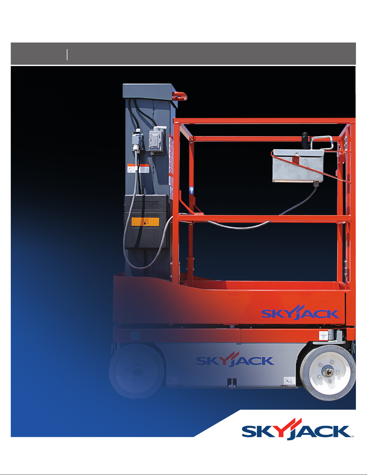
MODELS SJ 12
Operating Manual
Vertical Mast Series (ANSI/CSA)
Part No. 155169AB-A September 2010
Page 2

Skyjack Service Center 3451 Swenson Ave. St. Charles, Illinois, 60174 USA
Phone: 630-262-0005
Toll Free: 1-800-275-9522
Fax: 630-262-0006
Email: [email protected]
Parts (North America)
Toll Free: 1-800-965-4626
Toll Free Fax: 1-888-782-4825
E-mail: [email protected]
Parts & Service (Europe) Unit 1 Maes Y Clawdd, Maesbury Road Industrial Estate
Oswestry, Shropshire SY10 8NN UK
Phone: +44-1691-676-235
Fax: +44-1691-676-238
E-mail: [email protected]
Skyjack Asia Pacific
Singapore
Phone: +65-6449-3710
Fax: +65-6449-7690
E-mail: [email protected]
Page 3
TM
The Safety Alert Symbol identifies important
safety messages on aerial platform, safety signs
in manuals or elsewhere. When you see this
symbol, be alert to the possibility of personal
injury or death. Follow the instructions in the
safety message.
DANGER indicates an imminently hazardous situation which, if not avoided,
will result in death or serious injury.
WARNING indicates a potentially hazardous situation which, if not avoided,
could result in death or serious injury.
CAUTION indicates a potentially hazardous situation which, if not avoided,
may result in minor or moderate injury. It may also be used to alert against
This Safety Alert Symbol means attention!
Become alert! Your safety is involved.
DANGER
WARNING
CAUTION
unsafe practices.
IMPORTANT
IMPORTANT indicates a procedure essential for safe operation and which,
if not followed, may result in a malfunction or damage to the aerial platform.
This document is a translation from English.
In case of discrepancy between the English document and this document, the English
version prevails.
Vertical Mast Series
December 2007 Page 3
Page 4

TM
Table of Contents
Section 1 - About Your Aerial Platform
Read and Heed
Aerial Platform Definition .............................................................................................................................................7
Purpose of Equipment .................................................................................................................................................7
Use of Equipment ........................................................................................................................................................7
Manual ..........................................................................................................................................................................7
Operator .......................................................................................................................................................................7
Service Policy and Warranty ........................................................................................................................................7
Optional Accessories ...................................................................................................................................................7
Scope of this Manual ...................................................................................................................................................7
Safety Rules
Operator Safety Reminders .........................................................................................................................................8
Electrocution Hazard ...................................................................................................................................................9
Safety Precautions .....................................................................................................................................................10
Section 2 - Operation
2.1 General ............................................................................................................................................................15
2.1-1 Operator Qualifications .....................................................................................................................15
2.1-2 Operator’s Responsibility for Maintenance ......................................................................................15
2.1-3 Maintenance and Inspection Schedule ............................................................................................15
2.1-4 Owner’s Inspections .........................................................................................................................15
2.2 Major Components .........................................................................................................................................16
2.3 Major Assemblies ...........................................................................................................................................17
2.3-1 Base .................................................................................................................................................17
2.3-2 Lifting Mechanism .............................................................................................................................17
2.3-3 Platform .............................................................................................................................................17
2.4 Serial Number Nameplate ..............................................................................................................................17
2.5 Component Identification ...............................................................................................................................18
2.5-1 Main Power Disconnect Switch .......................................................................................................18
2.5-2 Brake System ....................................................................................................................................18
2.5-3 Base Control Console .......................................................................................................................18
2.5-4 Emergency Lowering System ...........................................................................................................19
2.5-5 Battery Charger .................................................................................................................................19
2.5-6 Hourmeter/Circuit Breaker/Diagnostic Switch ..................................................................................19
2.5-7 Tilt Alarm ...........................................................................................................................................19
2.5-8 Platform Control Console .................................................................................................................20
2.5-9 AC Outlet on Platform .......................................................................................................................20
2.5-10 Manual Storage Box .........................................................................................................................20
2.5-11 Pothole Protection Device.................................................................................................................21
2.5-12 Lanyard Attachment Anchorage .......................................................................................................21
2.5-13 Platform Maintenance Lock Mechanism ..........................................................................................22
Page 4 December 2007
Vertical Mast Series
Page 5

TM
Table of Contents
Section 2 - Operation (Continued)
2.6 Operator’s Responsibility ................................................................................................................................23
2.7 Visual and Daily Maintenance Inspections .....................................................................................................24
2.8 Function Tests..................................................................................................................................................29
2.9 Start Operation ................................................................................................................................................35
2.9-1 To Activate Base Control Console ....................................................................................................35
2.9-2 To Raise or Lower Platform Using Base Control Console ................................................................35
2.9-3 To Activate Platform Control Console ...............................................................................................36
2.9-4 To Raise or Lower Platform Using Platform Control Console ..........................................................36
2.9-5 To Drive Forward or Backward .........................................................................................................36
2.9-6 To Steer .............................................................................................................................................37
2.9-7 Shutdown Procedure ........................................................................................................................37
2.10 Loading/Unloading ..........................................................................................................................................38
2.10-1 Driving ...............................................................................................................................................38
2.10-2 Lifting .................................................................................................................................................39
2.11 Winching and Towing Procedures ..................................................................................................................40
2.11-1 To Release Brakes Manually .............................................................................................................40
2.12 Emergency Lowering Procedure ....................................................................................................................41
2.13 Platform Traversing (If equipped) ....................................................................................................................42
2.14 Accessing the Hydraulic/Electrical Compartment ..........................................................................................42
2.15 Battery Maintenance .......................................................................................................................................44
2.15-1 Battery Service Procedure ................................................................................................................44
2.15-2 Battery Charging Operation ..............................................................................................................44
2.16 Tables...............................................................................................................................................................46
2.17 Labels ..............................................................................................................................................................52
List of Tables
2.1 Standard and Optional Features .....................................................................................................................46
2.2 Owner’s Annual Inspection Record ................................................................................................................47
2.3 Specifications and Features ............................................................................................................................47
2.4 Maximum Platform Capacities (Evenly Distributed) .......................................................................................48
2.5 Floor Loading Pressure ...................................................................................................................................48
2.6 Maintenance and Inspection Schedule ..........................................................................................................50
2.7 Operator’s Checklist ........................................................................................................................................51
Vertical Mast Series
December 2007 Page 5
Page 6

TM
Section 1 - About Your Aerial Platform Read and Heed
SKYJACK is continuously improving and expanding product features on its equipment, therefore, specifications and
dimensions are subject to change without notice.
Aerial Platform and Mobile Elevating Work Platform Definition
A mobile device that has a positionable platform supported from ground level by a structure.
Purpose of Equipment
The SKYJACK Vertical Mast series aerial platforms are designed to transport and raise personnel, tools and
materials to overhead work areas.
Use of Equipment
The aerial platform is a highly maneuverable, mobile work station. Lifting and driving must be on a flat, level,
compacted surface.
Manual
The operating manual is considered a fundamental part of the aerial platform. It is a very important way to
communicate necessary safety information to users and operators. A complete and legible copy of this manual
must be kept in the provided weather-resistant storage compartment on the aerial platform at all times.
Operator
The operator must read and completely understand both this operating manual and the safety panel label located
on the platform and all other warnings in this manual and on the aerial platform. Compare the labels on the
aerial platform with the labels found within this manual. If any labels are damaged or missing, replace them
immediately.
1
Service Policy and Warranty
SKYJACK warrants each new Vertical Mast series aerial platform to be free of defective parts and workmanship for
the first 24 months. Any defective part will be replaced or repaired by your local SKYJACK dealer at no charge for
parts or labor. Contact the SKYJACK Service Department for warranty statement extensions or exclusions.
Optional Accessories
The SKYJACK aerial platform is designed to accept a variety of optional accessories.
Scope of this Manual
a. This manual applies to the ANSI/SIA, CSA version of the SJ12 Vertical Mast Series aerial platform models
listed on Table 2.1.
- Equipment identified with “ANSI” meets the ANSI SIA-A92.6-2006 standard.
- Equipment identified with “CSA” meets the CSA B354.2-01 standard.
b. CSA (Canada)
Operators are required to conform to national, territorial/provincial and local health and safety regulations
applicable to the operation of this aerial platform.
c. ANSI/SIA (United States)
Operators are required by the current ANSI/SIA A92.6 standards to read and understand their responsibilities
in the manual of responsibilities before they use or operate this aerial platform.
Vertical Mast Series
December 2007 Page 7
Page 7

TM
Safety Rules Section 1 - About Your Aerial Platform
WARNING
Failure to comply with your required responsibilities in the use and operation of the aerial platform
could result in death or serious injury!
Operator Safety Reminders
A study conducted by St. Paul Travelers showed that most accidents are caused by the failure of the operator to
follow simple and fundamental safety rules and precautions.
You, as a careful operator, are the best insurance against an accident. Therefore, proper usage of this aerial
platform is mandatory. The following pages of this manual should be read and understood completely before
operating the aerial platform.
Common sense dictates the use of protective clothing when working on or near machinery. Use appropriate safety
devices to protect your eyes, ears, hands, feet and body.
Any modifications from the original design are strictly forbidden without written permission from SKYJACK.
Page 8 December 2007
Vertical Mast Series
Page 8
TM
Section 1 - About Your Aerial Platform Safety Rules
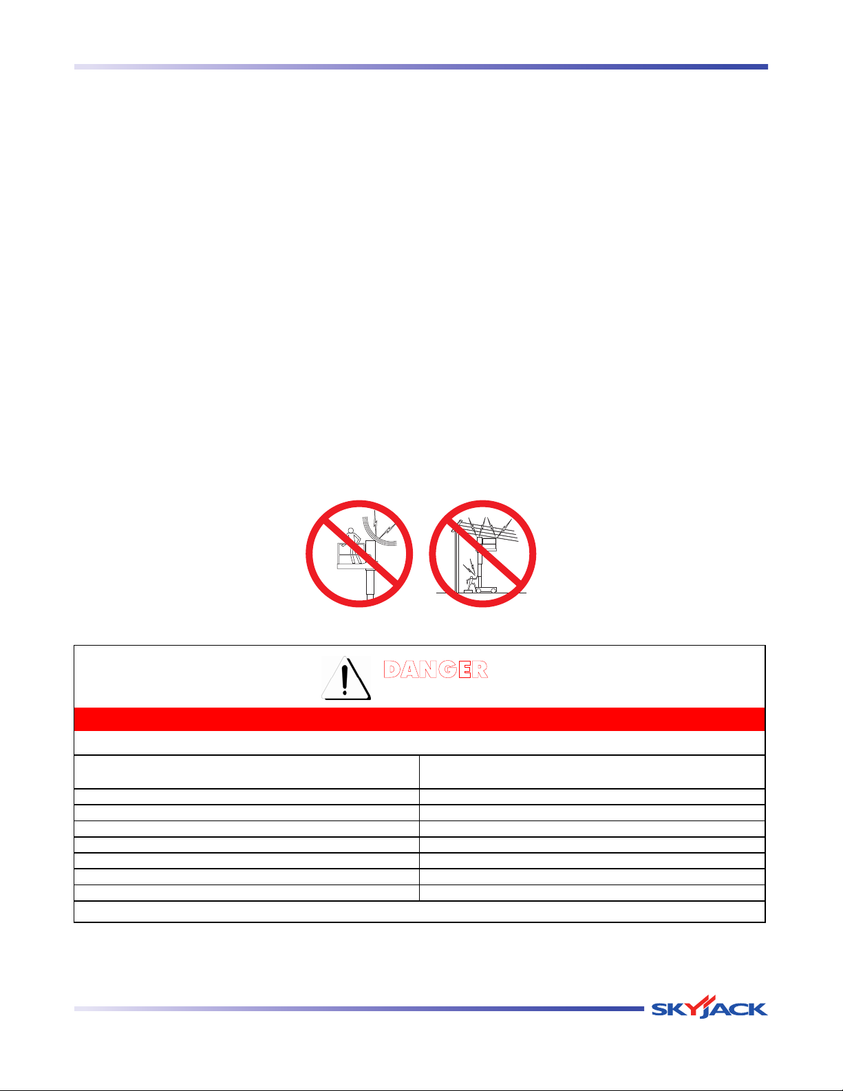
Voltage Range Minimum Safe Approach Distance
(Phase to Phase) (Feet)
0 to 300V Avoid Contact
Over 300V to 50KV 10
Over 50KV to 200KV 15
Over 200KV to 350KV 20
Over 350KV to 500KV 25
Over 500KV to 750KV 35
Over 750KV to 1000KV 45
60023AD-ANSI
DANGER
FAILURE TO AVOID THIS HAZARD WILL RESULT IN DEATH OR SERIOUS INJURY!
Avoid Power Lines
Minimum Safe Approach Distance
ANSI/SIA A92.6-2006 & CSA B354.2-01 Requirements
Electrocution Hazard
This aerial platform is not electrically insulated. Maintain a Minimum Safe Approach Distance (MSAD) from energized
power lines and parts as listed below. The operator must allow for the platform to sway, rock or sag. This aerial
platform does not provide protection from contact with or proximity to an electrically charged conductor.
Per ANSI A92.6-2006 8.10(7)
“The operator shall perform only that work for which he or she is qualified, in compliance with all applicable
safety related work practices intended to prevent electric shock covered by the Code of Federal Regulations
(CFR) 1910.333. The operator’s level of competence shall be established only by persons qualified to do so.
Operators shall maintain the appropriate minimum approach distance (MAD) from energized power lines and parts
covered by CFR 1910.333 (c).”
Unqualified persons must maintain a minimum approach distance of 10 feet from any energized power line up to
50 kV. Energized power lines over 50 kV require a greater minimum approach distance to be maintained. Refer to
CFR 1910.333.
As per CSA B354.2-01
“The operator shall maintain the minimum safe approach distance (MSAD) from energized conductors at all times
in accordance with the authority having jurisdiction.”
DO NOT USE THE AERIAL PLATFORM AS A GROUND FOR WELDING.
DO NOT OPERATE THE AERIAL PLATFORM DURING LIGHTNING OR STORMS.
Vertical Mast Series
December 2007 Page 9
Page 9
TM
Safety Rules Section 1 - About Your Aerial Platform
Safety Precautions
Know and understand the safety precautions before going on to next section.
WARNING
Failure to heed the following safety
precautions could result in tip over,
falling, crushing, or other hazards leading
to death or serious injury.
• KNOW all national, state or territorial/provincial
and local rules which apply to your aerial platform
and job site.
• TURN main power disconnect switch “ ” off when
leaving the aerial platform unattended. Remove
the key to prevent unauthorized use of the aerial
platform.
• WEAR all the protective clothing and personal
safety devices issued to you or called for by job
conditions.
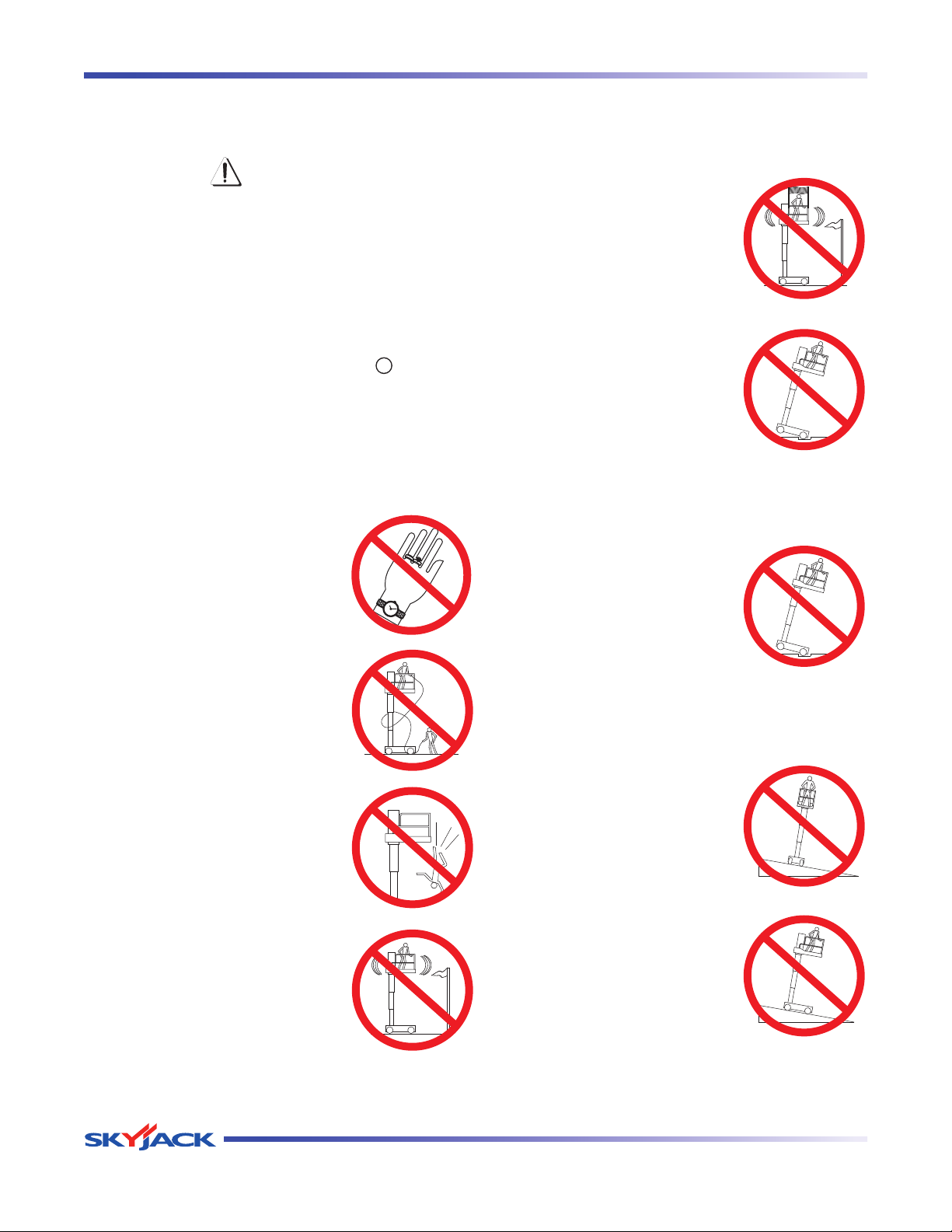
• DO NOT wear loose clothing,
dangling neckties, scarves,
rings, wristwatches or other
jewelry while operating this lift.
• AVOID entanglement with ropes,
cords or hoses.
• DO NOT increase the lateral
surface area of the platform.
Increasing the area exposed
to the wind will decrease aerial
platform stability.
• DO NOT drive or elevate the
aerial platform if it is not on a
firm level surface. Do not drive
elevated near depressions
or holes of any type, loading
docks, debris, drop-offs and
surfaces that may affect the
stability of the aerial platform.
• If operation in areas
with holes or drop-offs
is absolutely necessary,
elevated driving shall not be
allowed. Position the aerial
platform horizontally only with
the platform fully lowered. After
ensuring that all 4 wheels or
outriggers (if equipped) have
contact with level firm surface,
the aerial platform can be
elevated. After elevation, the
drive function must not be
activated.
• AVOID falling. Stay within the
boundaries of the guardrails.
• Elevated driving must
only be done on a firm level
surface.
• DO NOT ascend or descend
• DO NOT raise the aerial platform
in windy or gusty conditions.
a grade when elevated. When
fully lowered, ascending or
descending grades up to
maximum rated inclines listed
in Table 2.3.
Vertical Mast Series
Page 10 December 2007
Page 10
TM
Section 1 - About Your Aerial Platform Safety Rules
Safety Precautions (Continued)
Know and understand the safety precautions before going on to next section.
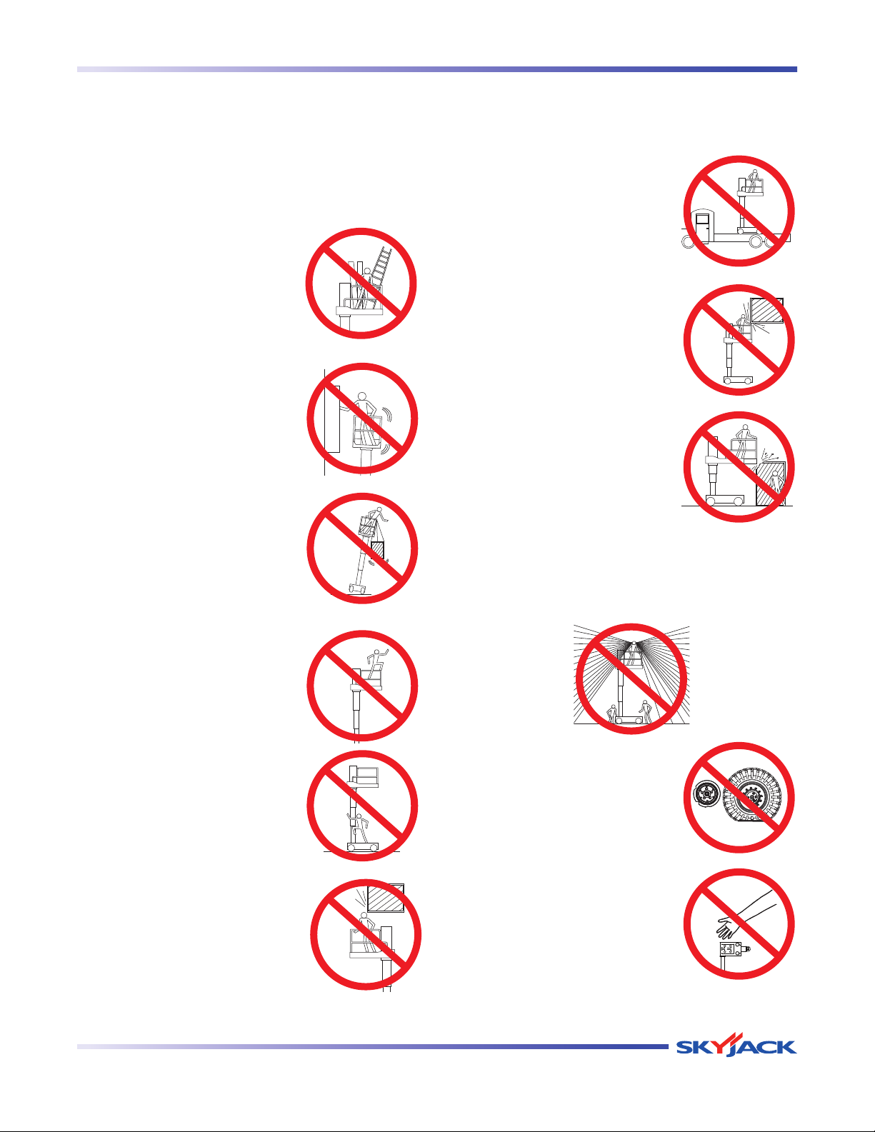
• DO NOT operate on surfaces not capable
of holding the weight of the aerial platform
including the rated load, e.g., covers, drains, and
trenches.
• DO NOT operate an aerial
platform that has ladders,
scaffolding or other devices
mounted on it to increase
its size or work height. It is
prohibited.
• DO NOT exert side forces on
aerial platform while elevated.
• DO NOT raise the aerial
platform while the aerial
platform is on a truck, fork lift
or other device or vehicle.
• BE AWARE of crushing
hazards. Keep all body parts
inside platform guardrail.
• DO NOT lower the platform
unless the area below is
clear of personnel and
obstructions.
• DO NOT use the aerial
platform as a crane. It is
prohibited.
• DO NOT sit, stand or climb on
the guardrails. It is prohibited.
• DO NOT climb on base and
mast. It is prohibited.
• BE AWARE of overhead
obstructions or other possible
hazards around the aerial
platform when driving or lifting.
• ENSURE that there are no personnel or
obstructions in the path of travel, including blind
spots.
• DO NOT use with improperly
inflated/damaged tires or
wheels. Tires should be
checked daily for pressure,
torn side walls and soft spots.
• DO NOT alter or disable
limit switches or other safety
devices.
Vertical Mast Series
December 2007 Page 11
Page 11
TM
Safety Rules Section 1 - About Your Aerial Platform
Safety Precautions (Continued)
Know and understand the safety precautions before going on to next section.
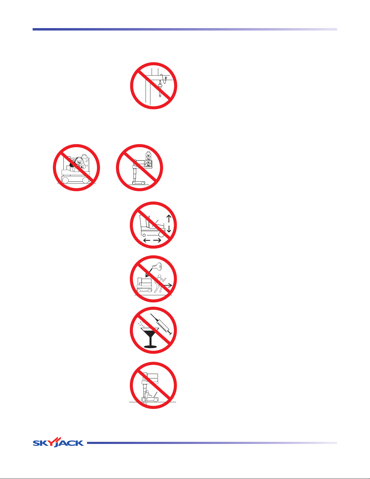
• DO NOT use the aerial
platform without guardrails,
locking pins and the entry
gate in place.
• DO NOT exceed the rated capacity of the
aerial platform. Do make sure the load is evenly
distributed on the platform.
• DO NOT operate if aerial
platform is not working
properly or if any parts are
damaged or worn.
• BE AWARE of blind spots when operating the
aerial platform.
• STUNT driving and horseplay are prohibited.
• DO NOT attempt to free a snagged platform with
lower controls until personnel are removed from
the platform.
• DO NOT position the aerial platform against
another object to steady the platform.
• DO NOT place materials on the guardrails
or materials that exceed the confines of the
guardrails unless approved by Skyjack.
• DO NOT leave aerial platform
unattended with key in key
switch.
• DO NOT use under influence
of alcohol or drugs.
• DO NOT access the
h y d r a u l i c / e l e c t r i c a l
compartment while the
platform is raised.
Page 12 December 2007
Vertical Mast Series
Page 12

TM
Section 2 - Operation General
Safety Precautions (Continued)
Know and understand the safety precautions before going on to next section.
Fall Protection
As per the ANSI A92.6-2006 standard, “The
guardrail system of the aerial platform provides
fall protection. If occupant(s) of the platform are
required to wear personal fall protection equipment
(PFPE), occupants shall comply with instructions
provided by the aerial platform manufacturer
(remanufacturer) regarding anchorage(s).”
If additional fall protection is required, by an
employer or the authority having jurisdiction,
Skyjack recommends the use of a fall restraint
system to keep an occupant within the confines
of the platform, and thus not expose the occupant
to any fall hazard requiring a fall arrest.
All personal fall protection equipment must
comply with applicable governmental regulations
and must be inspected and used in accordance
with the manufacturer’s recommendations.
All personal fall protection equipment must be
attached only to approved anchorage points
within the platform of the aerial platform.
WARNING
Entering and exiting the aerial platform
should only be done using the three
points of contact.
• Useonlyequippedaccessopenings.
• Enter and exit only when the aerial
platform is in the fully retracted position.
• Three points of contact means that two hands and
one foot or one hand and two feet are in contact
with the aerial platform or the ground at all times
during entering and exiting.
WARNING
An operator should not use any aerial
platform that:
does not appear to be working properly.•
has been damaged or appears to have worn or •
missing parts.
has alterations or modifications not approved by •
the manufacturer.
has safety devices which have been altered or •
disabled.
has been tagged or locked out for non-use or •
repair.
Failure to avoid these hazards could
result in death or serious injury.
Job site Inspection
Do not use in hazardous locations.•
Perform a thorough job site inspection prior to •
operating the aerial platform, to identify potential
hazards in your work area.
Be aware of moving equipment in the area. Take •
appropriate actions to avoid collision.
• Do use three points of contact to enter and exit
the platform. Enter and exit the platform from
the ground only. Face the aerial platform when
entering or exiting the platform.
Vertical Mast Series
December 2007 Page 13
Page 13
TM
Section 2 - Operation General
2.0 Operation
This section provides the necessary information needed
to operate the aerial platform. It is important that the user
reads and understands this section before operating
the aerial platform.
2.1 General
In order for this aerial platform to be in good working
condition, it is important that the operator meets the
necessary qualifications and follow the maintenance
and inspection schedule referred to in this section.
2.1-1 Operator Qualifications
Only trained and authorized personnel shall• be
permitted to operate an aerial platform.
Safe use of this aerial platform requires the •
operator to understand the limitations and
warnings, operating procedures and operator’s
responsibility for maintenance. Accordingly, the
operator must understand and be familiar with this
operating manual, its warnings and instructions,
and all warnings and instructions on the aerial
platform.
The operator must be sure that the aerial platform •
has been properly maintained and inspected
before using it.
The operator must perform all the daily inspections •
and function tests found in Table 2.6, even if
the operator is not directly responsible for the
maintenance of this aerial platform.
2.1-3 Maintenance and Inspection Schedule
The inspection points covered in • Table 2.6 indicate
the areas of the aerial platform to be maintained or
inspected and at what intervals the maintenance
and inspections are to be performed.
The actual operating environment of the aerial •
platform may affect the maintenance schedule.
WARNING
Use original or manufacturer-approved
parts and components for the aerial
platform.
2
The operator must be familiar with employer’s work •
rules and related government regulations and be
able to demonstrate the ability to understand and
operate this make and model of aerial platform in
the presence of a qualified person.
2.1-2 Operator’s Responsibility for
Maintenance
WARNING
Maintenance must be performed by
trained and competent personnel who are
familiar with mechanical procedures.
Death or serious injury could result from
the use of an aerial platform that is not
properly maintained or kept in good
working condition.
2.1-4 Owner’s Inspections
It is the responsibility of the owner to arrange daily,
quarterly (or 150 hours) and annual inspections of the
aerial platform. Refer to Table 2.6 for recommended
maintenance and inspection areas and intervals. A
record of annual inspection is kept on a label located
on the mast. Refer to Table 2.2 in this manual.
Vertical Mast Series
December 2007 Page 15
Page 14
TM
Major Components Section 2 - Operation
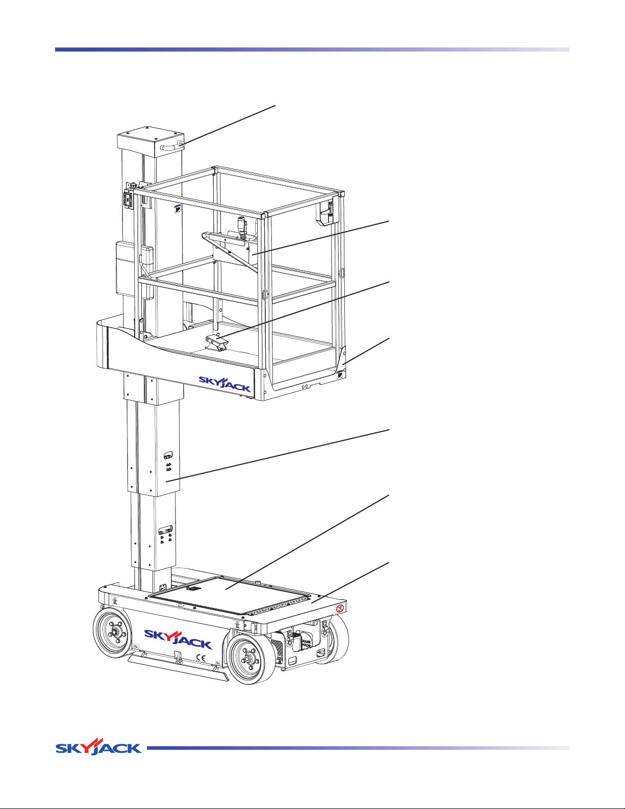
2.2 Major Components
Platform Repositioning Handle
Platform Control Console
Foot Pedal
Platform
Mast - Lifting Mechanism
Hydraulic/Electrical
Compartment
Access Door
Base
SKYJACK Vertical Mast Series Aerial Platform
Page 16 December 2007
Vertical Mast Series
Page 15

TM
Section 2 - Operation Major Assemblies
2.3 Major Assemblies
The aerial platform consists of three major assemblies:
base, lifting mechanism and platform.
2.3-1 Base
The base is a rigid, one-piece weldment which
contains hydraulic, electrical components and four
(4) 6 volt batteries. The front wheels are driven by
hydraulic motors, steerable by a hydraulic cylinder.
The rear wheels are non-driven, with spring-applied
hydraulically released brakes.
2.3-2 Lifting Mechanism
The lifting mechanism is constructed of formed
steel. The Mast assembly is raised and lowered by
a series of chains and a single-acting hydraulic lift
cylinder with holding valves. A pump, driven by an
electric motor, provides hydraulic power to the lift
cylinders.
2.3-3 Platform
The platform is constructed of a tubular support
frame, a skid-resistant “diamond plate” deck
surface and 43.25” fixed guardrails with 6” toe
boards and mid-rails. The platform can be entered
from the front through a spring-returned gate with
latch.
2.4 Serial Number Nameplate
The serial number nameplate, located at the rear of the
aerial platform, lists the following:
Model number•
Serial number•
Aerial platform weight•
Maximum drivable height•
Maximum capacities•
Maximum number of persons permissible on the •
platform
Voltage•
System pressure•
Lift pressure•
Maximum platform height•
Maximum wheel load•
Date manufactured•
Vertical Mast Series
December 2007 Page 17
Page 16
TM
Component Identification Section 2 - Operation
2.5 Component Identification
The following descriptions are for identification,
explanation and locating purposes only.
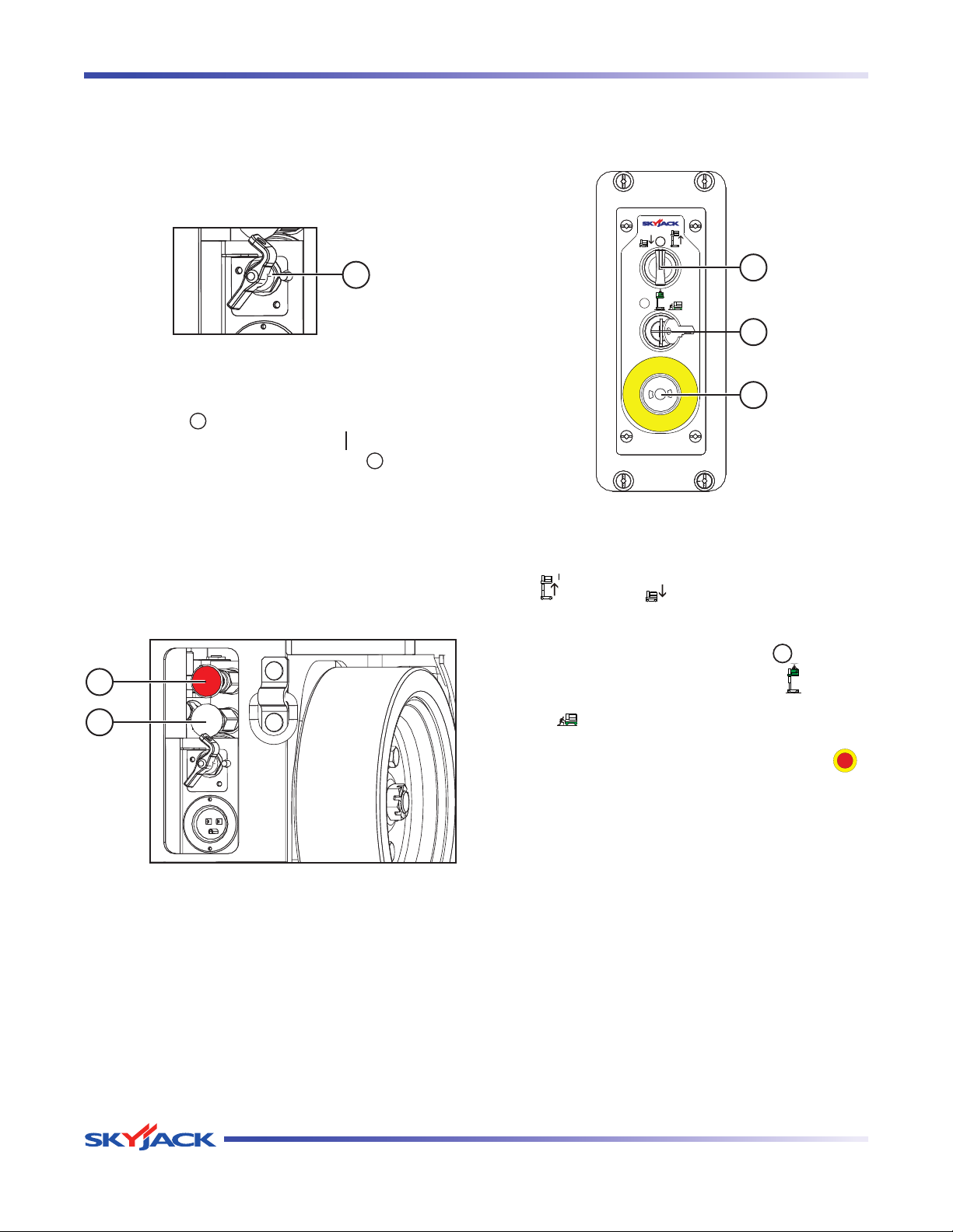
2.5-1 Main Power Disconnect Switch
This switch is located at the rear of the base.
1
Figure 2-1. Main Power Disconnect Switch
1. Main Power Disconnect Switch - This switch,
when in “ ” off position, disconnects power to
all circuits. Switch must be in “ ” on position to
operate any circuit. Turn switch “ ” off when
transporting aerial platform.
2.5-2 Brake System
The brake system is located at the rear of the base.
The brakes must be manually disengaged before
pushing, winching or towing. Refer to Section 2.11-1
for procedure on how to release brakes manually. The
system contains the following controls:
2.5-3 Base Control Console
This control console is located at the rear of the base.
It contains the following controls:
1
2
3
Figure 2-3. Base Control Console
1. Lower/Neutral/Raise Switch - This switch controls
“
” raising or “
” lowering of platform.
2. Off/Platform/Base Key Switch - This three-way
switch allows the operator to turn “ ” off power
1
2
Figure 2-2. Disc Brake System
1. Brake hand pump
2. Brake auto reset valve plunger
to aerial platform or to activate either “
or “
” base controls.
” platform
3. Emergency Stop Button - This button “ ”,
when depressed, disconnects power to the control
circuit.
Page 18 December 2007
Vertical Mast Series
Page 17
TM
Section 2 - Operation Component Identification
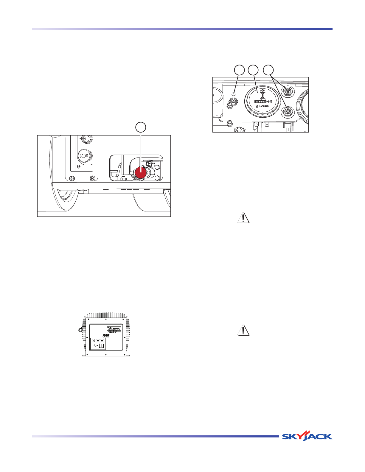
2.5-4 Emergency Lowering System
This emergency lowering system allows platform
lowering in the event of an emergency or an electrical
system failure.
1. Remove any obstructio ns from a loweri ng
platform.
2. Extension platform may need to be retracted or
aerial platform may need to be moved to clear
obstruction. Refer to Section 2.11 for winching
and towing procedures.
1
2.5-6 Hourmeter/Circuit Breaker/Diagnostic
Switch
This assembly is located inside the hydraulic/electrical
compartment.
23 1
Figure 2-6. Hourmeter/Circuit Breaker/Diagnostic
Switch
1. This gauge records accumulated operating time
of the aerial platform.
2. In the event of power overload or positive circuit
grounding, the circuit breaker pops out. Push
breaker back in to reset.
Figure 2-4. Emergency Lowering System
3. Locate emergency lowering valve (item 1) at
the base of the lift cylinder, pull out and hold
emergency lowering valve (item 1) to lower
platform.
2.5-5 Battery Charger
The charger is located at the front of the base. Refer to
Section 2.15-2 for battery charging operation.
Figure 2-5. Battery Charger
WARNING
Diagnostic switch should not be used
while any person are in the platform.
3. Diagnostic switch is used to check machine
functionality while the machine is in the service
position.
2.5-7 Tilt Alarm
The aerial platform is equipped with a device which
senses when the aerial platform is out of level in any
direction. When activated, it disables drive and lift
functions of the aerial platform and an alarm produces
an audible sound.
WARNING
If the tilt alarm sounds and the platform
doe s not , or onl y part ially raises ,
immediately lower the platform completely
and ensure that the aerial platform is on
a firm level surface.
Vertical Mast Series
December 2007 Page 19
Page 18
TM
Component Identification Section 2 - Operation
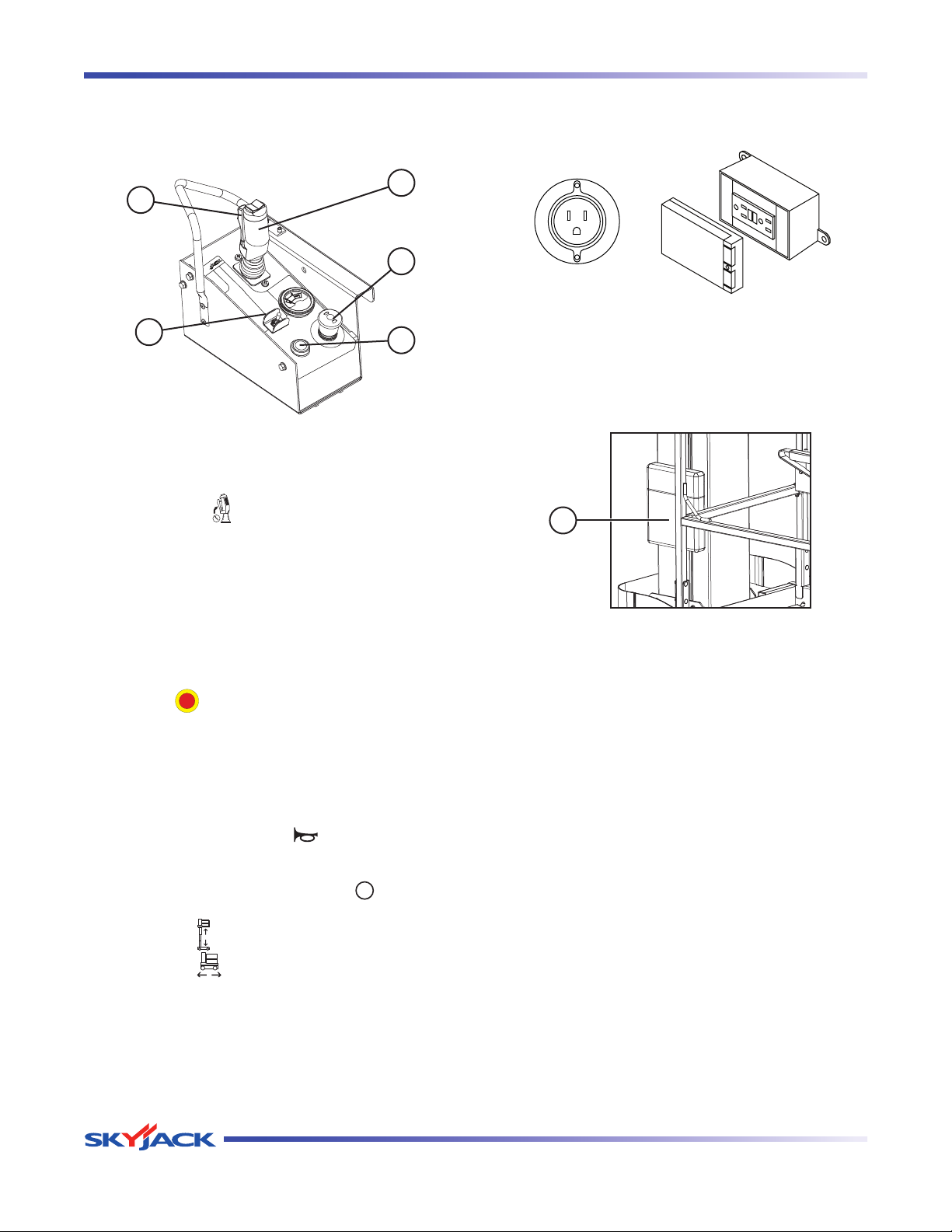
2.5-8 Platform Control Console
This removable control console is mounted at the right
front of the platform. It contains the following controls:
2
1
3
5
4
Figure 2-7. Platform Control Console
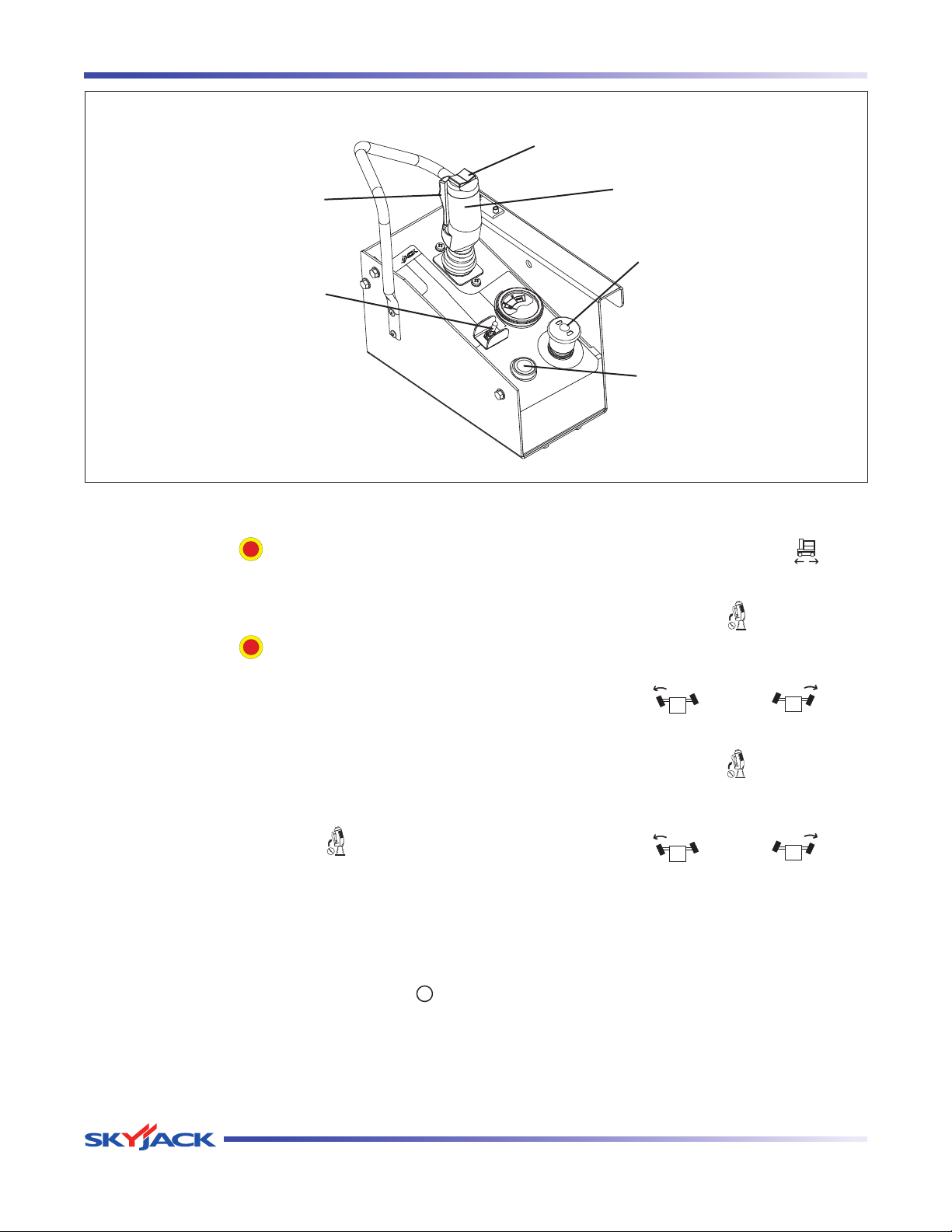
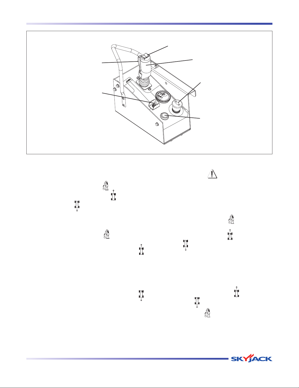
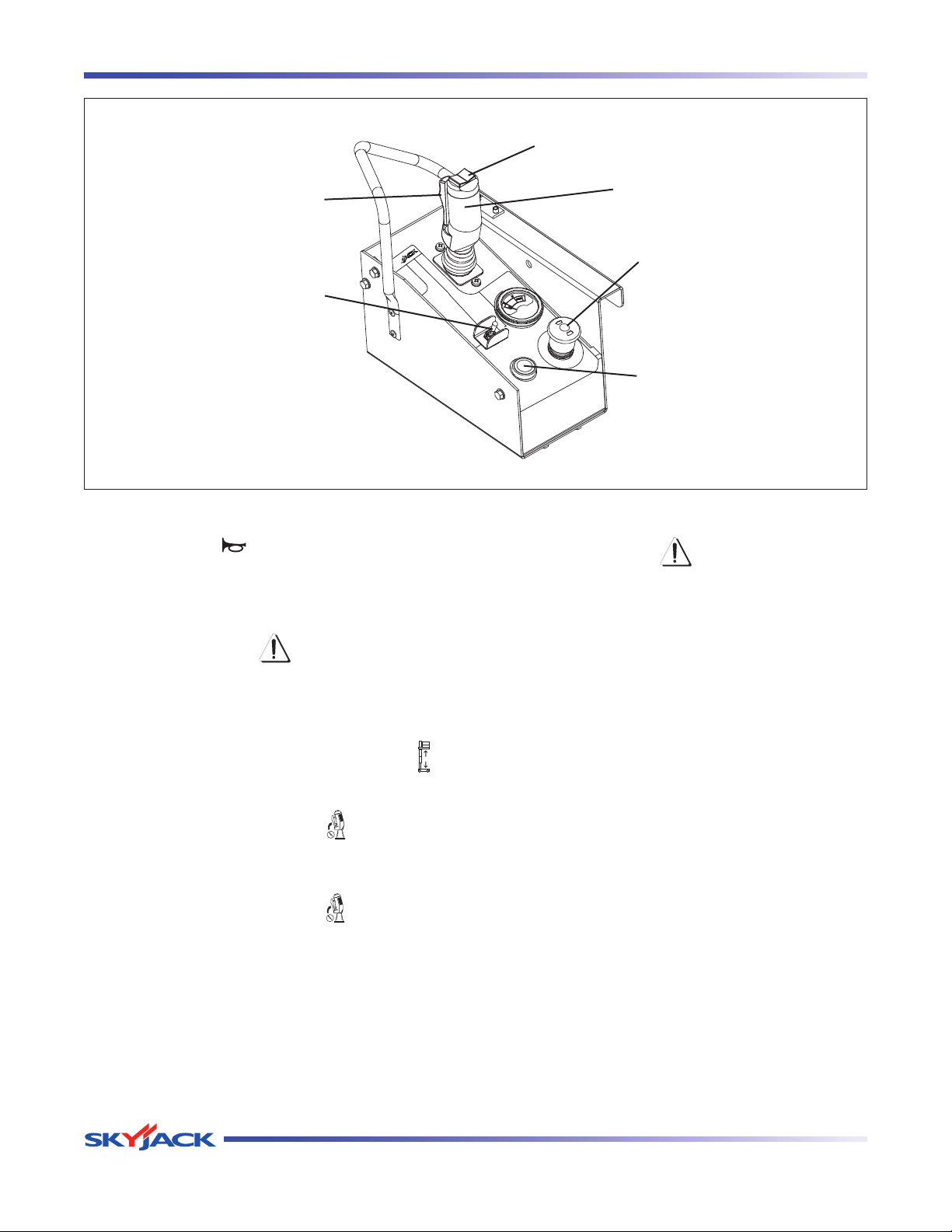
1. Lift/Drive/Steer Enable Trigger Switch - This
momentary “ ” switch energizes the controller.
It must be held depressed continuously while
engaging either the lift/drive or steer functions.
2.5-9 AC Outlet on Platform
This outlet is a source of AC power on the platform.
Figure 2-8. AC Outlet on Platform
2.5-10 Manual Storage Box
This weather-resistant box is mounted on the Mast. It
contains operating manual and certificate.
1
2. Lift/Drive/Steer Controller - This one-hand lever
controls lift/drive and steer motions. Internal
springs return it to neutral when controller is
released.
3. Emergency Stop Button/Operation Light - This
button “ ”, when depressed, disconnects power
to the control circuit. The operation light indicates
upper control availability. It glows when both
emergency stop buttons on the platform control
console and the base control console are pulled
out.
4. Horn Pushbutton - This “ ” pushbutton sounds
an automotive-type horn.
5. Lift/Off/Drive Switch - Selecting “ ” off position
disconnects power from both lift and drive circuits.
Selecting “ ” lift position energizes the lift circuit.
Selecting “ ” drive position energizes the drive
circuit.
Figure 2-9. Manual Storage Box
1. The operating manual for this make and model of
aerial platform must remain with the aerial platform
and should be stored in this box.
Page 20 December 2007
Vertical Mast Series
Page 19
TM
Section 2 - Operation Component Identification
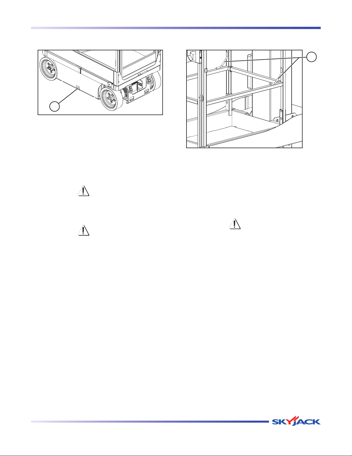
2.5-11 Pothole Protection Device
1
Figure 2-10. Pothole Protection Device
1. Pothole Protection Device - This device consists
of a set of mechanically actuated steel weldments
located under the base. These weldments will
automatically rotate for reduced ground clearance
when elevating the aerial platform. If the pothole
protection device has not fully lowered, the drive
function will be disabled.
WARNING
Crushing Hazard - Personnel on ground
must stay clear of pothole protection
device.
WARNING
Do not drive elevated in areas where
electrical cords or debris are in the path
of travel.
Maintenance of the Pothole
Protection Device
As with all safety devices, periodic inspection and
maintenance is required to ensure the proper
operation of the pothole protection device.
This mechanism is designed to reduce ground
clearance and assist in the stability of an elevated
aerial platform in the event the aerial platform
encounters a “drop-off” or “pothole.” The nature
of this safety feature relies on maintaining a
consistent ground clearance, therefore, if the aerial
platform ever does come to rest on the pothole
device, the platform should be immediately
lowered and “locked out” to prevent further use
until a complete inspection of the mechanism is
performed by a qualified technician.
2.5-12 Lanyard Attachment Anchorage
1
Figure 2-11. Lanyard Attachment Anchorage
1. Lanyard Attachment Anchorage - Use this as an
attachment point for safety belt/harness tethers.
Do not attach belts/harnesses to any other point
on the platform. Do not use this point to lift,
anchor, secure or support the platform or any
other apparatus or material.
WARNING
The la nyard attac hment anchor age
is used for travel restraint, within the
limits of the platform only. It is not a fall
arresting device! Use as such could result
in death or serious injury.
Vertical Mast Series
December 2007 Page 21
Page 20
TM
Component Identification Section 2 - Operation
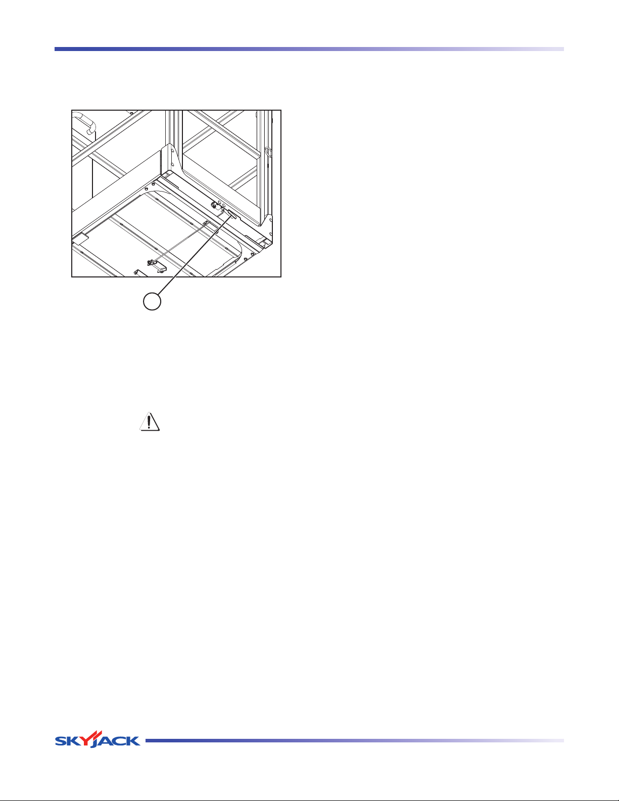
2.5-13 Platform Maintenance Lock Mechanism
This locking mechanism is located underneath the
platform.
1
Figure 2-12. Platform Maintenance Lock
1. The aerial platform is equipped with a maintenance
lock mechanism. When engaged, it allows access
to the hydraulic/electrical compartment. During
this access, it disables all functions.
CAUTION
Aerial platform motion can occur when
engaging diagnostic switch.
2. Hydraulic functions can be enabled by engaging
the diagnostic switch.
Page 22 December 2007
Vertical Mast Series
Page 21

TM
Section 2 - Operation Component Identification
2.6 Operator’s Responsibility
It is the responsibility of the operator, prior to each work
shift, to perform the following:
1. Visual and Daily Maintenance Inspections
are designed to discover any damage of •
components before the aerial platform is put
into service.
are done before the operator performs the •
function tests.
WARNING
Failure to locate and repair damage, and
discover loose or missing parts may
result in an unsafe operating condition.
2. Function Tests
are designed to discover any malfunctions •
before the aerial platform is put into service.
IMPORTANT
The operator must understand and
follow the step-by-step instructions
to test all aerial platform functions.
IMPORTANT
If aerial platform is damaged or any
unauthorized variation from factorydelivered condition is discovered, aerial
platform must be tagged and removed
from service.
Repairs to the aerial platform may only be made by a
qualified service technician. After repairs are completed,
the operator must perform visual and daily maintenance
inspections & function tests again.
Sc heduled maintenanc e ins pection s sha ll only
be performed by qualified service technician (see
Table 2.6).
The operator should make a copy of the Operator’s
Checklist (see Table 2.7) and fill out the visual and
daily maintenance inspections and the function
tests sections while performing the items outlined in
Section 2.7 and Section 2.8.
Vertical Mast Series
December 2007 Page 23
Page 22
TM
Component Identification Section 2 - Operation
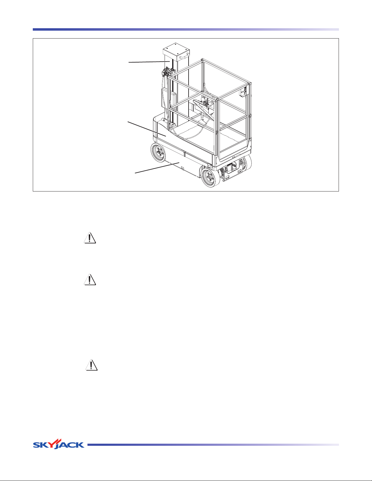
Mast
Platform
Base
2.7 Visual & Daily Maintenance Inspections
Begin the visual and daily maintenance inspections by
checking each item in sequence for the conditions listed
in this section.
WARNING
To avoid injury, do not operate an aerial
platform until all malfunctions have been
corrected.
WARNING
To avoid possible injury, ensure aerial
platform power is off during your visual
and daily maintenance inspections.
NOTE
While performing visual and daily inspections
in different areas, be aware to also inspect
limit switches, electrical and hydraulic
components.
CAUTION
Ensure aerial platform is on firm and level
ground.
2.7-2 Electrical
Maintaining the electrical components is essential to good
performance and service life of the aerial platform.
Inspect the following areas for chafed, corroded and
loose wires:
• allwiringharnesses
• hydraulic/electricalwiringharnesses
2.7-3 Limit Switches
Ensure limit switches are properly secured with no signs
of visible damage and movement is not obstructed.
2.7-4 Hydraulic
Maintaining the hydraulic components is essential to good
performance and service life of the aerial platform.
Perform a visual inspection around the following
areas:
hoses and fittings•
hydraulic cylinder•
all hydraulic manifolds•
the underside of the base•
ground area under the aerial platform•
2.7-1 Labels
Refer to the labels section in this manual and determine
that all labels are in place and are legible.
Page 24 December 2007
Vertical Mast Series
Page 23
TM
Section 2 - Operation Component Identification (Special Options)
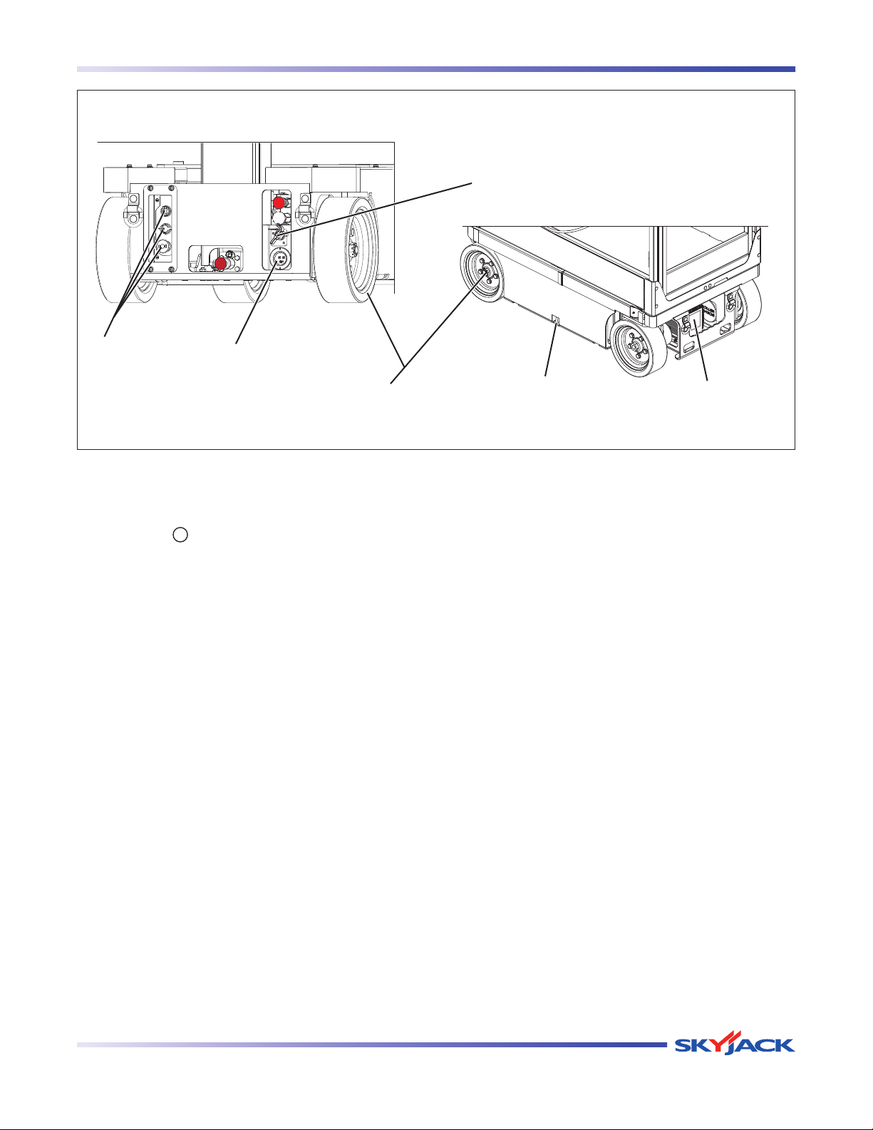
Main Power Disconnect Switch
Base Control
Switches
2.7-5 Base
Main Power Disconnect Switch •
Base Control Switches•
110/220V Outlet Receptacle•
Battery Charger•
Steer Cylinder Assembly•
110/220V Outlet
Receptacle
Wheel/Tire Assembly
Turn main power disconnect switch to -
“ ” off position.
Ensure all cables are secure and switch is -
in proper working condition.
Ensure there are no signs of visible -
damage and all switches are in their
neutral positions.
Ensure receptacle is free from dirt and -
obstructions.
Ensure charger is secure and shows no -
visible damage.
Ensure steer cylinder assembly is properly -
secured and there are no loose or missing
parts.
Pothole Protection
Device
Battery Charger
Wheel/Tire Assembly•
The aerial platform is equipped with solid
rubber tires. Tire and/or wheel failure could
result in an aerial platform tip-over. Component
damage may also result if problems are not
discovered and repaired in a timely fashion.
Check all tire treads and sidewalls for cuts, -
cracks, punctures and unusual wear.
Check ea ch wheel fo r damage an d -
cracked welds.
Check each lug nut for proper torque to -
ensure none are loose.
Check wheel motor assembly for loose -
or missing parts and signs of visible
damage.
Ensure wheels are aligned and t rue -
vertically and horizontally.
Pothole Protection Device•
Ensure mechanisms have no sign of -
visible damage and are free from dirt and
obstructions.
Vertical Mast Series
December 2007 Page 25
Page 24
TM
Operator’s Responsibility Section 2 - Operation
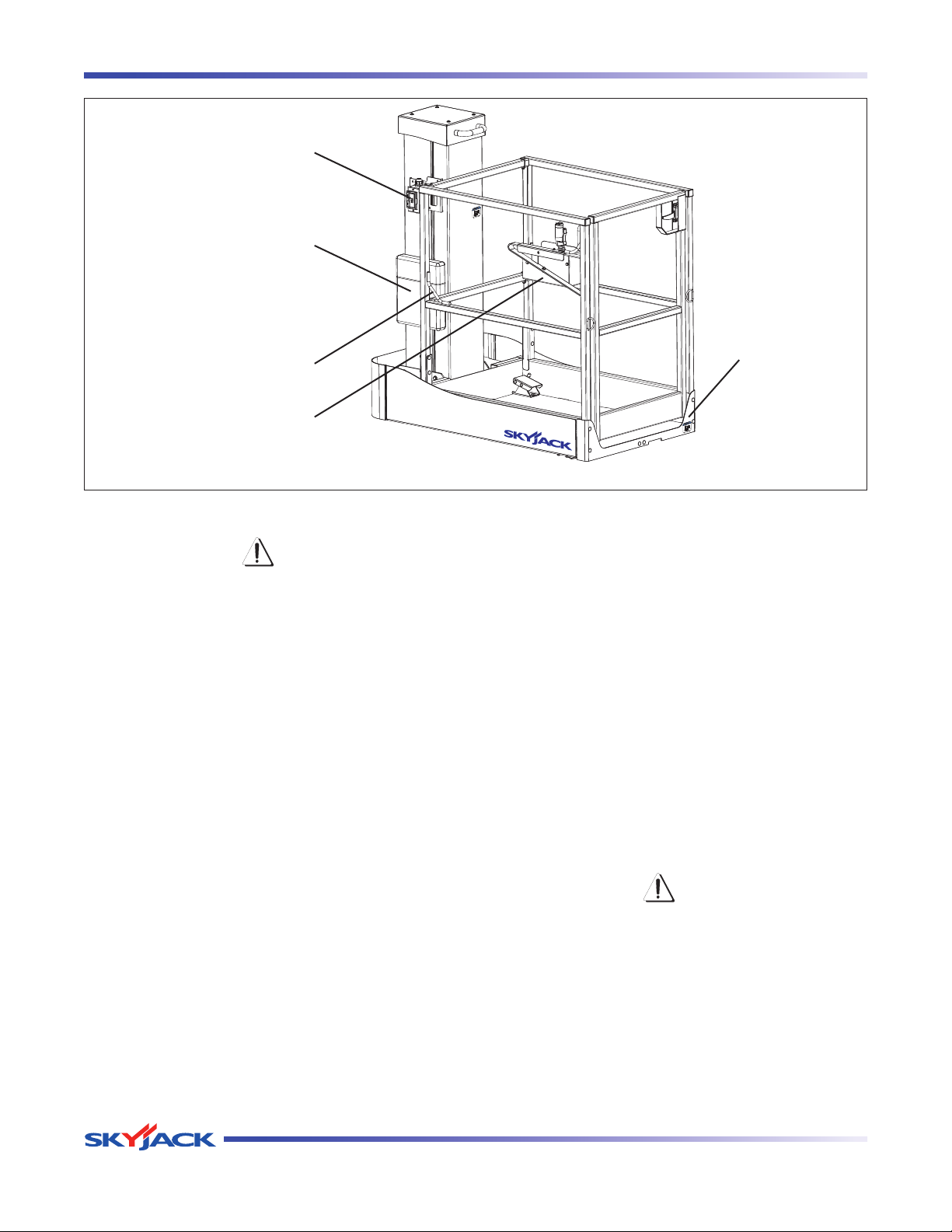
AC Outlet
Manuals Box
Platform Assembly
Lanyard Attachment Anchors
Platform Control Console
2.7-6 Platform Assembly
WARNING
Ensure that you maintain three points of
contact to mount/dismount platform.
1. Open the gate and access the platform.
2. Close the gate.
Ensure all railings are properly positioned -
and secured.
Ensu re all fasteners are securely in -
place.
Ensure gate is in good working order. -
Ensure there are no loose or missing parts -
and there is no visible damage.
Ensure platform foot pedal is in good -
working order and no loose or missing
parts and there is no visible damage
Lanyard Attachment Anchors•
Ensure attachment anchors are secure -
and no visible damage.
AC Outlet•
Ensure outlet has no visible damage and -
free from dirt or obstructions.
Platform Control Console•
Ensure all switches and controller are -
returned to neutral and are properly
secured.
Ensure there are no loose or missing parts -
and there is no visible damage.
Manuals•
Ensure a copy of operating manual and
certificate are enclosed in manual storage
box.
Check to be sure manual storage box is -
present and in good condition.
Ensure manuals are legible and in good -
condition.
Always return manuals to the manual -
storage box after use.
WARNING
Ensure that you maintain three points of
contact to mount/dismount platform.
3. Dismount from platform.
4. Close the gate.
Page 26 December 2007
Vertical Mast Series
Page 25
TM
Section 2 - Operation Operator’s Responsibility
Hydraulic Pump and Motor
Batteries
Main Manifolds
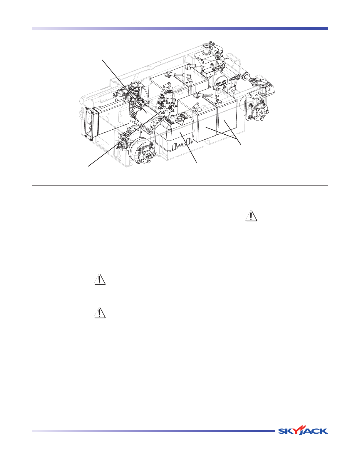
2.7-7 Hydraulic/Electrical Compartment
1. To access the hydraulic/electrical compartment,
refer to Section 2.14.
Battery•
Proper batt ery condition is esse ntial t o
good performance and operational safety.
Improper fluid levels or damaged cables and
connections can result in component damage
and hazardous conditions.
WARNING
Explosion hazard. Keep flames and sparks
away. Do not smoke near batteries.
WARNING
Battery acid is extremely corrosive - Wear
proper eye and facial protection as well
as appropriate protective clothing. If
contact occurs, immediately flush with
cold water and seek medical attention.
a. Check battery case for damage.
b. Clean battery terminal s and cabl e ends
thoroughly with a terminal cleaning tool or wire
brush.
c. Ensure all battery connections are tight.
d. If applicable, check battery fluid level. If plates
are not covered by at least 1/2” (13 mm) of
solution, add distilled or demineralized water.
Hydraulic
Tank
e. Replace battery if damaged or incapable of
holding a lasting charge.
WARNING
Use original or manufacturer-approved
parts and components for the aerial
platform.
Battery Charger•
Ensure charger is secure and shows no -
visible damage.
Main Manifolds•
Ensure all fittings and hoses are properly -
tightened and there is no evidence of
hydraulic leakage.
Ensure there are no loose wires or missing -
fasteners.
Hydraulic Tank •
Ensure hydraulic filler cap is secure. -
Ensure tank shows no visible damage and -
no evidence of hydraulic leakage.
Hydraulic Pump and Motor •
Ensure there are no loose or missing parts -
and there is no visible damage.
Vertical Mast Series
December 2007 Page 27
Page 26
TM
Start Operation Section 2 - Operation
Cables (Rear)
Motor Controller
Tilt Sensors
Mast Assembly
Pothole Protection Device
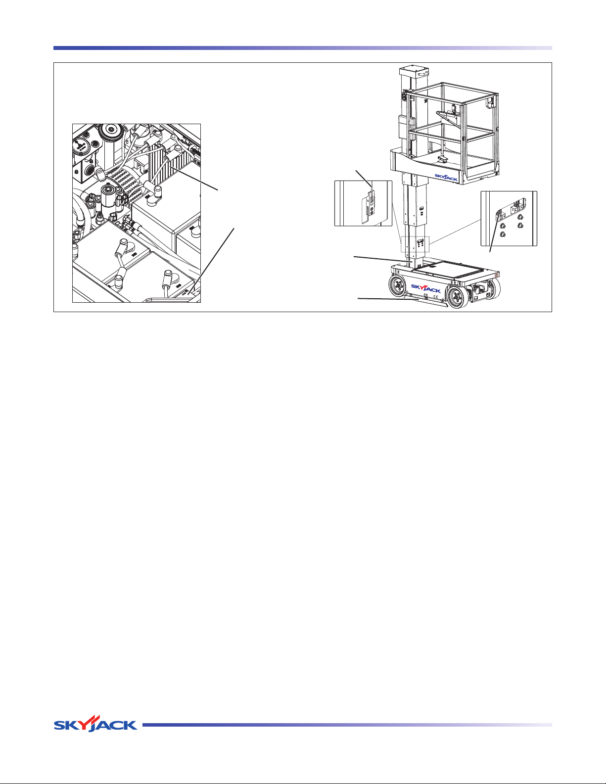
Hydraulic Oil•
Ensure platform is fully lowered, and then -
visually inspect the hydraulic oil level
Motor Controller •
Ensure the controller is properly secured -
and there is no visible damage.
Ensure there are no loose wires or missing -
fasteners.
Tilt Sensors •
Ensure tilt sensors are properly secured -
and there is no visible damage.
Pothole Protection Device•
Ensure mechanisms have no sign of -
visible damage and are free from dirt and
obstructions.
Limit Switches•
Ensure limit switches are properly secured -
with no signs of visible damage and
movement is not obstructed.
2. Close the compartment access door and latch
in place.
3. Push the platform back to its operating position
and latch in place.
Chains (Front)
2.7-8 Lifting Mechanism
Mast Assembly•
Ensure mast assembly shows no visible -
damage and no signs of deformation in
weldments.
1. Complete Section 2.8 - Function Tests.
2. Raise the platform.
Wear Pads•
Ensure all bolts are tight, there is no visible -
damage to the wear pads and that no parts
are missing.
Chains•
Ensure there are no missing parts, and -
all bolts are tight with no signs of visible
damage.
Ensure chains are securely anchored. -
Cables•
Ensure there are no missing parts, and -
all bolts are tight with no signs of visible
damage.
Ensure cables are secure within sheave -
rollers.
Page 28 December 2007
Vertical Mast Series
Page 27
TM
Section 2 - Operation Start Operation
Main Power
Disconnect
Switch
Base
Emergency
Stop
2.8 Function Tests
Function tests are designed to discover any malfunctions
before aerial platform is put into service. The operator
must understand and follow step-by-step instructions to
test all aerial platform functions.
WARNING
Never use a malfunctioning aerial platform.
If malfunctions are discovered, aerial
platform must be tagged and placed out
of service. Repairs to aerial platform
may only be made by a qualified service
technician.
After repairs are completed, operator must perform a
pre-operation inspection and a series of function tests
again before putting aerial platform into service.
Prior to performing function tests, be sure to read and
understand Section 2.9 - Start Operation.
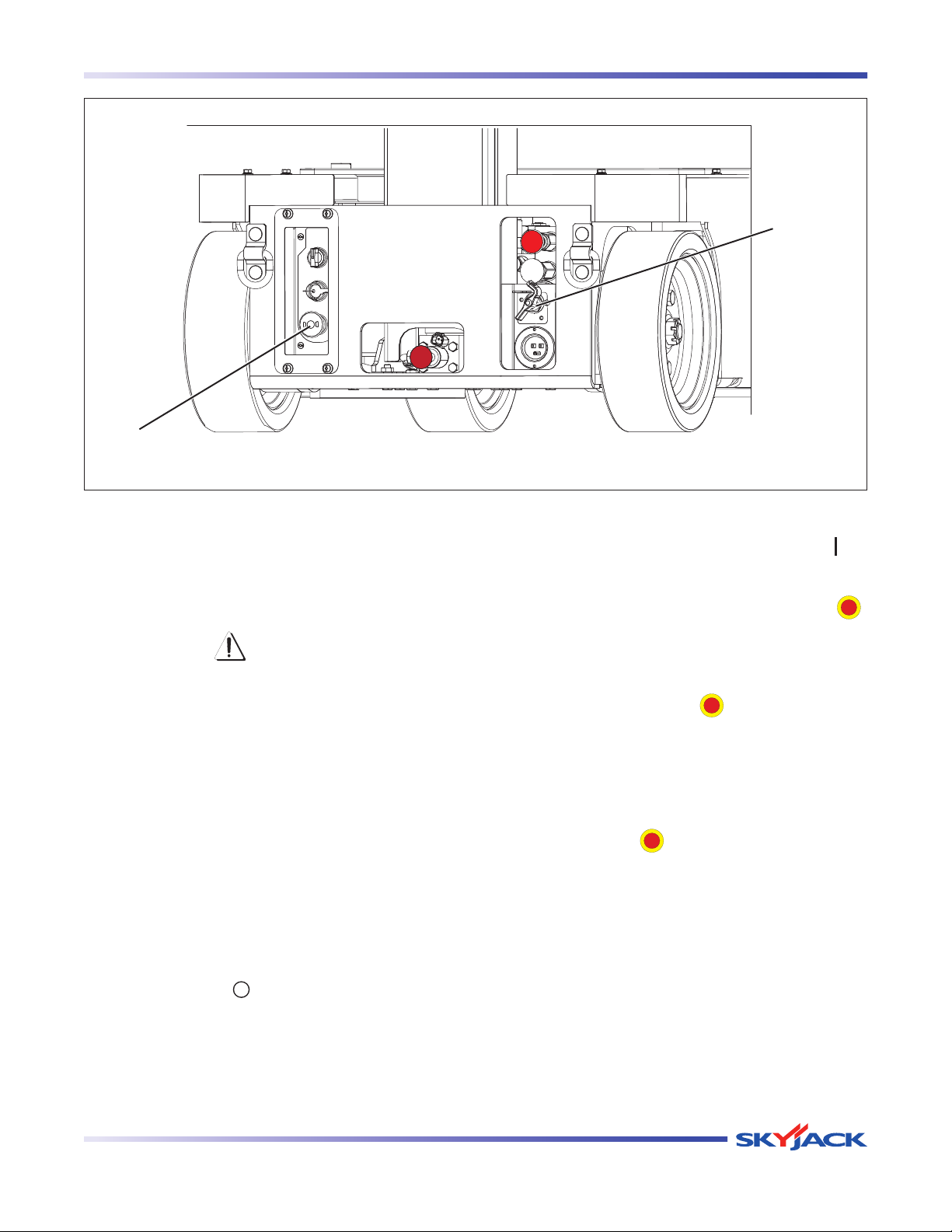
2.8-1 Test Main Power Disconnect Switch
2.8-2 Base Control Console
1. Turn main power disconnect switch to “ ” on
position.
2. On platform control console, pull out “ ”
emergency stop button.
Test Base Emergency Stop Light•
1. Pull out base “ ” em ergency st op
button.
Result: Emergency stop light should
continuously illuminate.
Test Base Emergency Stop•
1. Push in “ ” emergency stop button and
attempt to raise or lower the platform.
Result: Platform raising and lowering
functions should not operate.
1. At rear of the base, turn main power disconnect
switch to “ ” off position and attempt to
activate all aerial platform functions.
Result: Aerial platform functions should not
operate.
Vertical Mast Series
December 2007 Page 29
Page 28
TM
Start Operation Section 2 - Operation
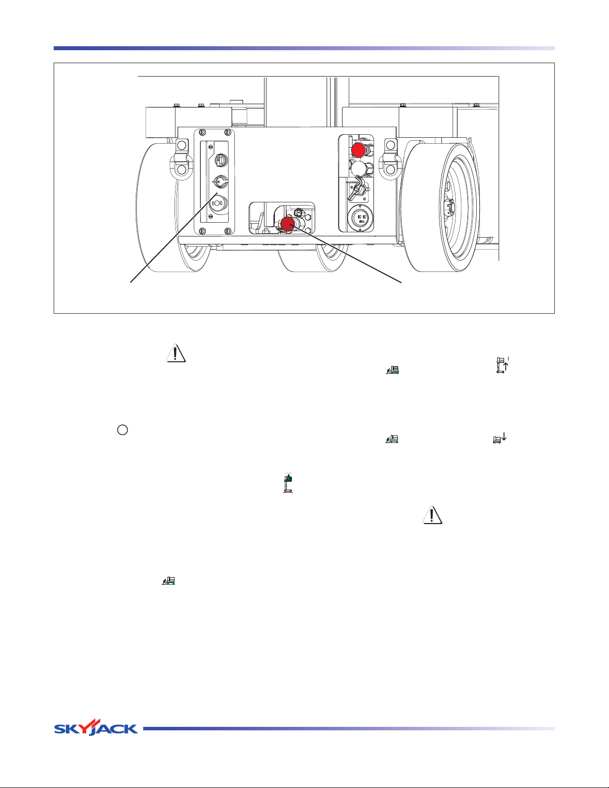
Base Control Console Emergency Lowering
Test Off/Platform/Base Switch•
WARNING
Be aware of overhead obstructions
or other possible hazards around the
aerial platform when lifting.
1. Select off/platform/base key switch to
“ ” off position. Attempt to raise or lower
the platform.
Result: Platform raising and lowering
functions should not operate.
2. Select off/platform/base key switch to “
platform position. Attempt to raise or lower
the platform.
Result: Platform raising and lowering
functions should not operate.
3. Select and hold off/platform/base key
switch to “
” base position. Attempt to
raise or lower the platform.
Result: Platform raising and lowering
functions should operate.
Test Lower/Neutral/Raise Switch•
1. Select and hold off/platform/base key switch
to “
” base position and “
” raise the
platform with lower/neutral/raise switch.
Result: Platform should rise.
2. Select and hold off/platform/base key switch
to “
” base position and “
” lower the
platform with lower/neutral/raise switch.
Result: Platform should lower.
”
Test Emergency Lowering•
WARNING
Be aware of overhead obstructions
or other possible hazards around the
aerial platform when lifting.
1. Raise the platform.
2. On rear of the base, pull out and hold
emergency lowering valve to fully lower the
platform.
Result: The platform should lower.
Page 30 December 2007
Vertical Mast Series
Page 29
TM
Section 2 - Operation Start Operation
Base Control Console Emergency Lowering
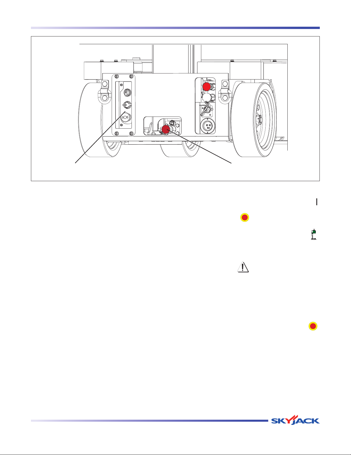
2.8-3 Test Platform Maintenance Limit Switch
1. Traverse the platform to maintenance position,
refer to Section 2.14.
2. At the platform control console, attempt to
activate any function.
Result: All functions should not operate.
3. Push the platform back to its operating position
and latch in place.
2.8-4 Platform Control Console
1. Ensure main power disconnect switch is in “ ”
on position.
2. Ensure base “ ” emergency stop button is
pulled out.
3. Select off/platform/base key switch to “
platform position.
WARNING
Ensure that you maintain three points of
contact to mount/dismount platform.
4. Open the gate and access the platform.
5. Close the gate.
6. On platform control console, pull out “ ”
emergency stop button.
”
Vertical Mast Series
December 2007 Page 31
Page 30
TM
Start Operation Section 2 - Operation
Rocker Switch
Lift/Drive/Steer Enable
Trigger Switch
Lift/Off/Drive Switch
Test Platform Emergency Stop•
1. Push in “ ” emergency stop button and
attempt to activate any platform function.
Result: All selected platform functions
should not operate.
2. Pull out “ ” emergency stop button.
3. While activating any platform functions,
push in emergency stop button.
Result: Current activated aerial platform
functi o n sho u l d i m m e diately stop
operating.
Test Enable Trigger Switch•
1. Without activating “ ” enable trigger
switch, attempt to activate any platform
function.
Result: All platform functions should not
operate.
Controller
Emergency Stop Button/
Operation Light
Horn Pushbutton
Test Steering•
1. Select lift/off/drive switch to “ ” drive
position.
2. Without activating “ ” enable trigger
switch.
3. Press rocker switch on top of controller
handle to “ ” left and “ ” right.
Result: Steer wheels should not operate
4. Activate and hold “ ” enable trigger
switch.
5. Press rocker switch on top of controller
handle to “ ” left and “ ” right.
Result: Steer wheels should turn left and
right.
Test Lift/Off/Drive Switch Off Position•
1. Se le ct lif t/off/drive switch to “ ” off
position, attempt to activate any platform
function.
Result: All platform functions should not
operate.
Page 32 December 2007
Vertical Mast Series
Page 31
TM
Section 2 - Operation Start Operation
Rocker Switch
Lift/Drive/Steer Enable
Trigger Switch
Lift/Off/Drive Switch
Test Driving•
1. Ensure path of intended motion is clear.
2. Without activating “ ” enable trigger
switch attempt to drive “ ” forward and
reverse “ ”.
Result: Aerial platform drive functions
should not operate.
Controller
Emergency Stop Button/
Operation Light
Horn Pushbutton
Test Brakes•
WARNING
Brakes will engage instantly when you
release the controller handle, causing
aerial platform to stop immediately.
1. Ensure path of intended motion is clear.
2. Activate and hold “ ” enable trigger
switch.
3. Activate a nd hold “ ”enable trigger
switch.
4. Slowly move controller handle in “ ”
forward direction until aerial platform begins
to move, and then return handle to center
position.
Result: Aerial platform should move in
forward direction, and then come to a
stop.
5. Slowly move controller handle in “ ”
reverse direction until aerial platform begins
to move, and then return handle to center
position.
Result: Aerial platform should move in
reverse direction, and then come to a
stop.
Vertical Mast Series
3. Drive aerial platform “ ” forward and then
“ ” backward. Test brake by releasing
controller handle.
Result: Aerial platform should come to a
stop. If aerial platform pulls to one side
while stopping, do not operate aerial
platform until brake adjustments have been
checked.
4. Drive aerial platform “ ” forward and
then “ ” backward. Test brake again by
releasing “ ” enable trigger switch only.
Result: Aerial platform should come to an
instant and abrupt stop. If aerial platform
does not stop immediately, or if aerial
platform pulls to one side while stopping,
do not operate aerial platform until brake
adjustments have been checked.
December 2007 Page 33
Page 32
TM
Start Operation Section 2 - Operation
Rocker Switch
Lift/Drive/Steer Enable
Trigger Switch
Lift/Off/Drive Switch
Test Horn•
1. Push “ ” horn pushbutton.
Result: Horn should sound.
Test Platform Raising/Lowering•
WARNING
Be aware of overhead obstructions
or other possible hazards around the
aerial platform when lifting.
Controller
Emergency Stop Button/
Operation Light
Horn Pushbutton
Test Pothole Sensor •
WARNING
Ensure that you maintain three points of
contact to mount/dismount platform.
1. Dismount from platform and place a block,
approximately 1.5” (3.75 cm), under one
side of the pothole protection device.
2. Open the gate and access the platform.
1. Se lect lift/off/d rive switch to “ ” lif t
position.
2. Without activating “ ” enable trigger
switch attempt to lift/lower the platform.
Result: Aerial platform lift/lower functions
should not operate.
3. Activate and hold “ ” enable trigger
switch.
4. Push controller handle and raise the
platform to an approximate height of 1 ft.
(30.5 cm).
Result: Platform should rise.
5. Pull controller handle and lower the platform
fully.
Result: Platform should lower.
Page 34 December 2007
3. Close the gate.
4. Raise the platform until approximately a
height of 2 feet is reached and attempt to
drive forward or reverse.
Result: Aerial platform should not move
forward or backward.
5. Repeat the steps above with block placed
under the o the r-side of th e po tho le
protection device.
Result: Aerial platform should not move
forward or backward.
Vertical Mast Series
Page 33
TM
Section 2 - Operation Start Operation
2.9 Start Operation
Carefully read and completely understand the operating
manual and all warnings and instruction labels (refer to
labels section) on the aerial platform.
WARNING
Do not operate this aerial platform without
proper authorization and training. Failure
to avoid this hazard could result in death
or serious injury.
Before operating this aerial platform, perform the
following steps:
1. Visual and daily maintenance inspections (see
Section 2.7)
2. Function tests (see Section 2.8)
3. Job site inspection
It is the responsibility of the operator to perform
a job site inspection and avoid the following
hazardous situations:
holes or drop-offs•
ditches or soft fills•
floor obstructions, bumps or debris•
overhead obstructions•
electrical cords, hoses and high voltage •
conductors
hazardous locations•
inadequate surface support to withstand all •
load forces imposed by the aerial platform
wind and weather conditions•
the presence of unauthorized personnel•
other possible unsafe conditions•
2.9-1 To Activate Base Control Console
WARNING
Ensure that you maintain three points of
contact to mount/dismount platform.
1. Open the gate and access the platform.
2. Close the gate.
3. On platform control console, pull out “ ”
emergency stop button.
4. Dismount from platform.
5. Turn main power disconnect switch to “ ”on
position.
6. On base control console, pull out “ ” emergency
stop button.
2.9-2 To Raise or Lower Platform Using Base
Control Console
WARNING
Be aware of overhead obstructions or
other possible hazards around the aerial
platform when lifting.
WARNING
Do not lower the platform unless the area
is clear of personnel and obstructions.
WARNING
An operator should not use any aerial platform
that:
does not appear to be working properly.•
has been damaged or appears to have worn or •
missing parts.
has alterations or modifications not approved by •
the manufacturer.
has safety devices which have been altered or •
disabled.
Failure to avoid these hazards could result in death
or serious injury.
Vertical Mast Series
December 2007 Page 35
1. Select and hold off/platform/base key switch to
“
” base position.
2. Select and hold lower/neutral/raise switch to either
“
” raise or “
” lower position. Release switch
to stop.
Page 34
TM
Start Operation Section 2 - Operation
2.9-3 To Activate Platform Control Console
1. Turn main power disconnect switch to “ ”on
position.
2. On base control console, pull out “ ” emergency
stop button.
3. Select base/off/platform key switch to “
platform position.
WARNING
Ensure that you maintain three points of
contact to mount/dismount platform.
4. Open the gate and access the platform.
5. Close the gate.
6. On platform control console, pull out “ ”
emergency stop button.
4. Return controller to neutral center position to stop.
Release “ ” enable trigger switch.
WARNING
To protect against unintended movement of
the aerial platform, push in the emergency
stop button after you have arrived at your
desired location or elevation.
”
NOTE
If the tilt alarm sounds and the platform does
not, or only partially raises, immediately
lower the platform completely and ensure
that the aerial platform is on a firm level
surface.
2.9-5 To Drive Forward or Backward
WARNING
Be aware of blind spots when operating
the aerial platform.
2.9-4 To Raise or Lower Platform Using
Platform Control Console
WARNING
Be aware of overhead obstructions or
other possible hazards around the aerial
platform when lifting.
WARNING
Do not lower the platform unless the area
below is clear of personnel and
obstructions.
1. On platform control console, select lift/off/drive
switch to “
” lift position.
2. Activate and hold “ ” enable trigger switch.
3. Move controller handle forward or backward until
desired height is reached.
WARNING
Ensure that there are no personnel
or obstructions in the path of travel,
including blind spots.
1. On platform control console, select lift/off/drive
switch to drive “
” position.
2. Activate and hold “ ” enable trigger switch.
3. Move controller handle “ ” forward/up or
“ ” backward/down to desired speed and
direction of aerial platform travel.
4. Return controller to neutral center position to stop.
Release “ ” enable trigger switch.
WARNING
To protect against unintended movement of
the aerial platform, push in the emergency
stop button after you have arrived at your
desired location or elevation.
Page 36 December 2007
Vertical Mast Series
Page 35
TM
Section 2 - Operation Start Operation
2.9-6 To Steer
1. On platform control console, select lift/off/drive
switch to drive “
” position.
2. Activate and hold “ ” enable trigger switch.
3. Press “ ” rocker switch on top of controller
handle in either direction to steer.
NOTE
Steering is not proportional. Driving and
steering may be active at the same time.
2.9-7 Shutdown Procedure
1. Completely lower the platform.
2. On platform control console, push in “ ”
emergency stop button.
WARNING
Ensure that you maintain three points of
contact to mount/dismount platform.
3. Dismount from platform.
4. On base control console, push in “ ” emergency
stop button.
5. On base control console, select off/platform/base
key switch to “ ” off position and remove the
key.
6. Turn main power disconnect switch to “ ” off
position.
Vertical Mast Series
December 2007 Page 37
Page 36
TM
Loading/Unloading Section 2 - Operation
2.10 Loading/Unloading
Know and heed all national, state or territorial/provincial
and local rules which apply to your loading/unloading
of aerial platforms.
Only qualified personnel shall operate machinery
during loading/unloading.
Be sure vehicle capacity and loading equipment
hoists, chains, straps, etc., are sufficient to withstand
maximum aerial platform weight.
The transport vehicle must be parked on a level surface
and must be secured to prevent rolling while aerial
platform is being loaded/unloaded.
Tie down/lifting
points
2.10-1 Driving
Before driving the aerial platform:
Ramp or dock capacity should be sufficient to •
withstand maximum aerial platform weight.
Ramp should be equipped with side guards to •
prevent inadvertent fall from the ramp.
Incli ne shou ld no t e xceed aeri al plat form •
gradeability, as illustrated in Figure 2-14.
Aerial platform brakes should be checked for •
proper operation.
WARNING
When transporting, the aerial platform
must be secured to the truck or trailer
deck. Tie downs are available as illustrated
in Figure 2-13.
Tie down/lifting
points
Tie down/lifting
points
Figure 2-13. Tie Downs/Lifting Points
30% 25%
Gradeability 30%: Climbing reverse - Descending forward
Gradeability 25%: Climbing forward - Descending reverse
Figure 2-14. Maximum Gradeability of Inclined Driving
Page 38 December 2007
Tie down/lifting
points
Vertical Mast Series
Page 37
TM
Section 2 - Operation Winching and Towing Procedures
24.885”
18.536”
2.10-2 Lifting
WARNING
Only qual ified rigge r s hall oper ate
machinery during lifting.
When it is necessary to lift the aerial platform, the
following conditions must be met:
The platform must be fully lowered.•
The main power disconnect switch must be in •
“ ” off position.
The traversing platform must be retracted and •
secured.
The platform control console must be secured to •
the railing or removed.
The platform must be cleared of all personnel, •
tools and materials.
The lifting/rigging may be attached to all four lifting •
points as illustrated in Figure 2-13.
NOTE
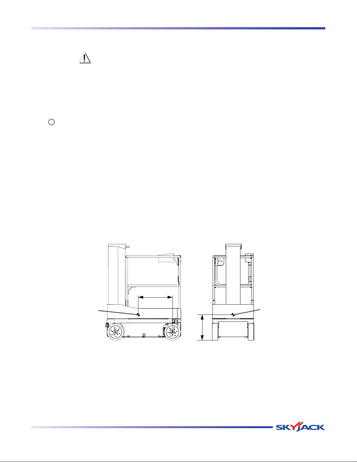
The mass of the aerial platform is as
per Table 2.3. The center of gravity is
approximately located in the middle of the
aerial platform, front to back and side to
side, as illustrated in Figure 2-15. Vertically,
the center of gravity is approximately just
above the base chassis.
Center of
gravity
Vertical Mast Series
Center of
gravity
Figure 2-15. Center of Gravity
December 2007 Page 39
Page 38
TM
Winching and Towing Procedures Section 2 - Operation
2.11 Winching and Towing Procedures
This section provides the operator with procedures
about towing and winching and on how to manually
release the brakes.
WARNING
Ensure platform is fully lowered before
winching or towing. Sudden motion could
cause the aerial platform to become
unstable. Death or serious injury could
result.
WARNING
In emergency situations where aerial
platform functions are not available and
lowering is impeded by an obstacle,
utmost care must be taken to move
aerial platform far enough to clear the
obstacle. In such cases, operation must
be extremely smooth with no sudden
movements and must not exceed a speed
of 2”/sec (50 mm/sec).
WARNING
When pushing, winching or towing, do
not exceed 2 mph (3.2 km/h).
WARNING
Do not push, winch or tow aerial platform
onto a slope, or brake the towing vehicle
rapidly. Do not pull aerial platform down
an incline towards a winch.
2.11-1 To Release Brakes Manually
WARNING
Do not manually disengage brakes if the
aerial platform is on a slope.
WARNING
Brakes must be manually disengaged for
pushing, winching or towing.
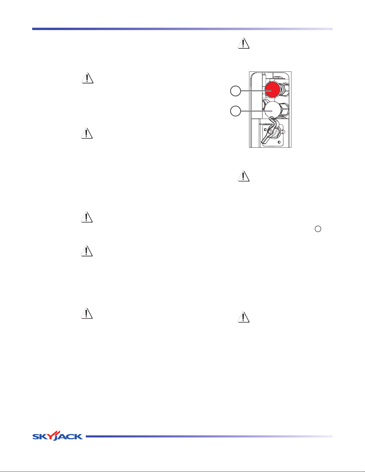
1
2
Figure 2-16. Brakes
WARNING
Brakes must be manually disengaged for
pushing, winching or towing.
1. Ensure aerial platform is on level ground. Chock
or block wheels to keep aerial platform from
rolling.
2. Turn main power disconnect switch to “ ” off
position.
3. Locate the brake manifold at the rear of the
base.
4. Push in brake auto reset valve plunger (item 2).
5. Grasp brake hand pump (item 1) and rapidly
depress until firm resistance is felt. The brakes
are now released.
6. Remove wheel chocks or blocks, then push, winch
or tow aerial platform to desired location.
7. Position aerial platform on a firm and level
surface.
WARNING
Brakes must be reengaged immediately
after reaching the desired location.
8. Chock or block wheels to prevent aerial platform
9. Reengage the brake by pulling out the brake auto
Page 40 December 2007
from rolling.
reset valve plunger.
Vertical Mast Series
Page 39
TM
Section 2 - Operation Emergency Lowering Procedure
2.12 Emergency Lowering Procedure
This section guides the operator on how to use the
emergency lowering system. This system allows
platform lowering in the event of an emergency or an
electrical system failure.
WARNING
Keep clear of lifting mechanism when
using emergency lowering valve.
1. Remove any obstructio ns from a loweri ng
platform.
2. Platform may need to be retracted or aerial platform
may need to be moved to clear obstruction.
Refer to Section 2.11 for winching and towing
procedures.
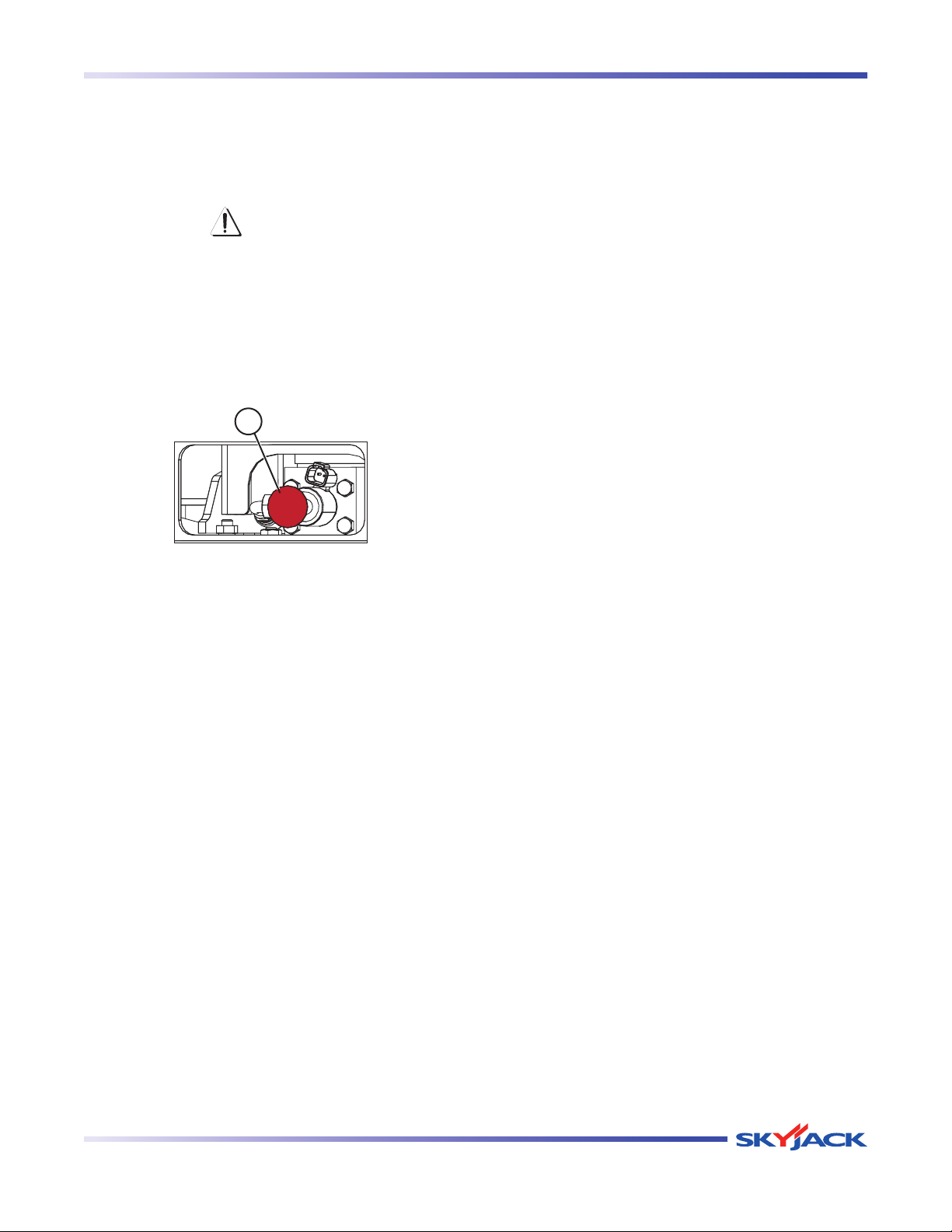
1
Figure 2-17. Emergency Lowering System
3. Locate the emergency lowering valve (item 1) at
the base of the lift cylinder (rear of the base). Pull
out and hold emergency lowering valve (item 1)
to lower platform.
Vertical Mast Series
December 2007 Page 41
Page 40
TM
Platform Traversing Procedure Section 2 - Operation
2.13 Platform Traversing
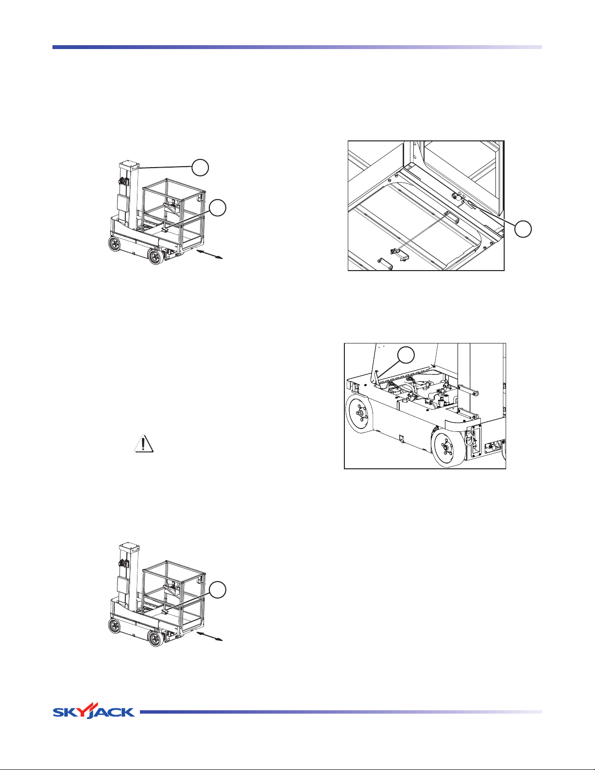
1. To traverse platform, step on the foot pedal on
the platform (item 1) and grasp the platform
repositioning handle (item 2) then carefully
push/pull the platform until desired location is
reached.
2
1
Figure 2-18.Traversing Platform
2. Ensure foot pedal (item 1) rests in one of the
locking slots.
2.14 Accessing the Hydraulic/Electrical
Compartment
4. Locate platform maintenance locking mechanism
underneath the platform.
5. Unlatch maintenance locking mechanism by
pulling and holding the handle (item 2), then pull
the platform fully to the maintenance position.
2
Figure 2-20. Maintenance Lock
6. Open hydraulic/electrical compartment cover and
properly install the prop bar (item 3).
3
1. Ensure aerial platform is on firm and level
ground.
2. Fully lower the platform into stowed position.
CAUTION
The following procedure must be done
from outside of the platform.
3. Depress foot pedal on the platform (item 1),
then pull platform as far as possible towards
maintenance position.
1
Figure 2-21. Prop Bar
Figure 2-19.Traversing Platform
Page 42 December 2007
Vertical Mast Series
Page 41
TM
Battery Maintenance Section 2 - Operation
2.15 Battery Maintenance
This section provides the operator with procedures
on how to service and charge the battery. This also
provides charger operation instructions.
2.15-1 Battery Service Procedure
WARNING
Explosion Hazard - Keep flames and
sparks away. Do not smoke near
batteries.
WARNING
Battery acid is extremely corrosive - Wear
proper eye and facial protection as well as
appropriate protective clothing. If contact
occurs, immediately flush with cold water
and seek medical attention.
1. Turn main power disconnect switch to “ ” off
position.
2. Check battery case for damage.
3. Check battery fluid level in each battery. If plates
are not covered by at least 1/2” (13 mm) of
solution, add distilled or demineralized water.
4. Clean battery terminals and cable ends thoroughly
with a terminal cleaning tool or wire brush.
5. Make sure all battery connections are tight.
6. Replace any battery that is damaged or incapable
of holding a lasting charge.
7. Do not use any batteries other than flooded leadacid batteries of the proper Ah rating.
2.15-2 Battery Charging Operation
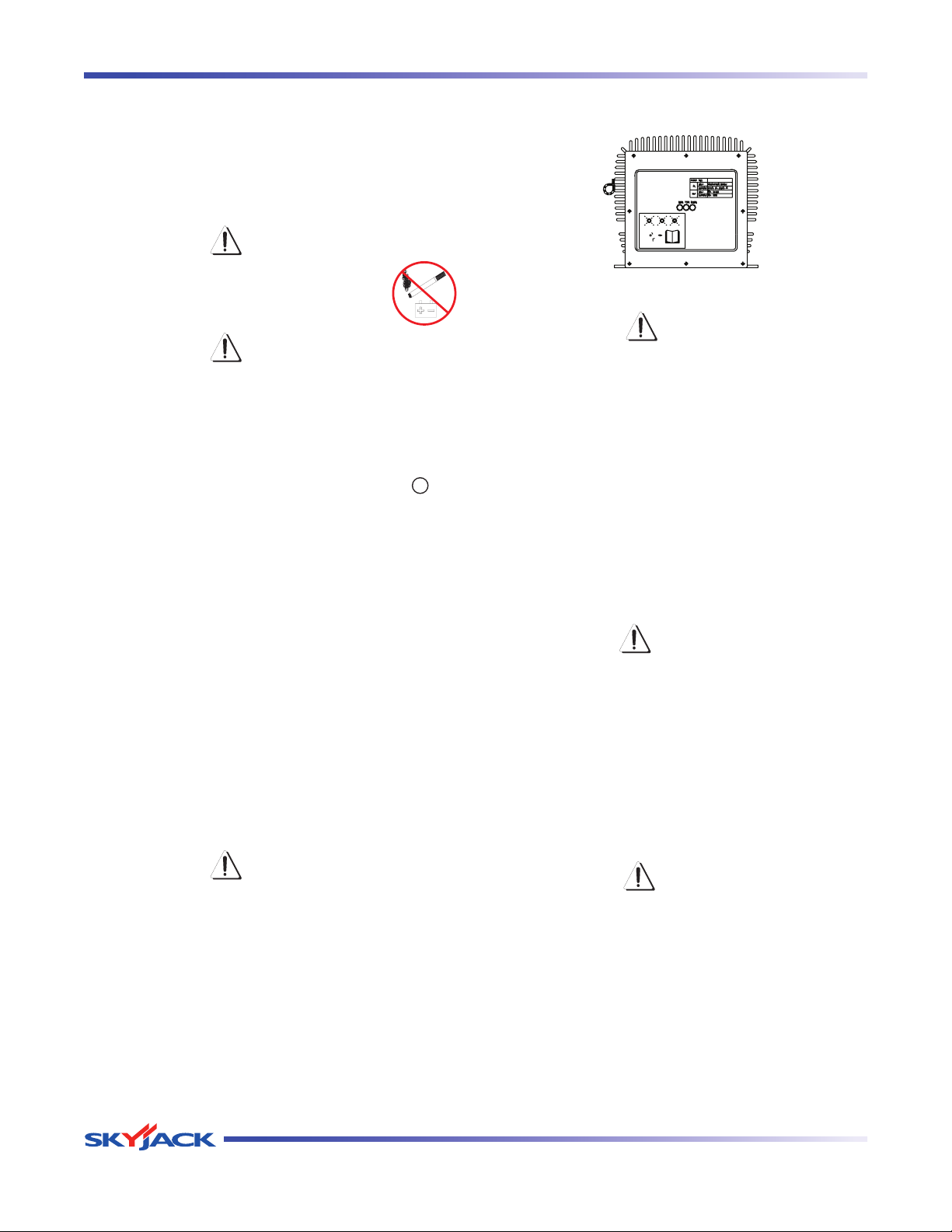
Figure 2-22. Battery Charger
DANGER
Risk of electric shock - Do not immerse
the charger in water. Though the charger
is highly resistant to water, it is not
designed for immersion and an electric
shock can occur.
1. Provide adequate ventilation for the batteries and
charger. The convection cooled design requires
access to cooling air for proper operation. Do
not allow blankets or other materials to cover
the charger. Although the charger protects itself
against overheating, the charger cooling fins
should be cleaned if clogged with debris for best
performance.
WARNING
There could be a spark during charging.
Be careful when using fuels, solvents or
other flammables near the charger or
batteries.
2. Connect the power supply cord to a properly
grounded 100V/50 or 60Hz, 115V/50 or 60Hz, or
230V/50 or 60Hz socket. This charger automatically
senses and adjusts to the AC input voltage
range.
WARNING
Use original or equivalent to the original
parts and components for the aerial
platform.
Page 44 December 2007
CAUTION
When changing the input voltage wait
until all the LEDs are OFF or wait a
minimum of 20 seconds before switching
on the new voltage.
Vertical Mast Series
Page 42
TM
Section 2 - Operation Battery Maintenance
State of charge 1ST LED 2ND LED 3RD LED
0 to 50% Blinking Off Off
50% to 75% On Blinking Off
75% to 100% On On Blinking
100% On On On
3. The charging time is affected by numerous
factors including battery Amp-Hour capacity,
depth of discharge, battery temperature, and
battery condition (new, old or defective). Batteries
larger than 240 AH can be recharged but will take
longer.
WARNING
Do not disconnect the DC output wires
near the batteries when the charger is
ON. The resulting arcing could cause
the batteries to explode. If the charger
must be disconnected, first disconnect
th e AC power supply cord from it s
outlet, then disconnect the charger DC
connections.
WARNING
Risk of an electric shock - Do not touch
un-insulated parts of the charger output
wires, battery connector, or battery
terminals.
WARNING
Visually and manually inspect to verify the
DC output wires and terminals are in good
working condition before each use.
4. The charger will start automatically within four
to six seconds. The charger will start even with
severely discharged batteries (down to 1V terminal
voltage). Once charging starts, the LEDs indicate
the charging progress.
Charging State LED
3 LEDs blink once simultaneously:
Output connection error. Check the battery and charger
connection. The output may not be connected to the
batteries or the connections to the batteries may have
corroded or loosened. The output may be shorted due
to improper connection to the batteries or pinched
wires. The output may be connected in reverse polarity
to the batteries. The charger is not damaged by any of
these problems.
3 LEDs blink twice simultaneously:
The charger is indicating that the AC voltage is too low
or too high. Check the AC input voltage.
3 LEDs blink three times simultaneously:
Charger is overheated. No action required. When
the charger cools, charging will restart automatically.
Check and correct for dirt or other debris on charger
that may be reducing cooling.
3 LEDs blink four times simultaneously:
Input or output over current. No action required,
charger will correct and restart automatically.
100% LED lamp blinks:
Charger 18-hour timer has timed out due to battery
problem.
Batteries do not fully charge.
If the batteries are charged overnight, make sure the
AC supply is not being switched off at night with other
building items. Check battery condition and for dead
cells or reduced capacity. Replace charger only if other
problems are not found.
The AC line circuit breaker or fuse is blown.
A defective circuit breaker or fuse, an overloaded
circuit, or a charger problem can cause this condition.
Try connecting the charger to a different AC outlet
(on a different circuit) in the building. If the AC supply
checks good, the charger should be replaced.
The charger goes into an equalizing charge mode after
the batteries are charged and all 3 LEDs are “ON”. The
charger will continue to charge at a low current then
shut off automatically when complete. If all 3 LEDs
blink together, there is a problem.
Take proper action according to the following
instructions:
Vertical Mast Series
December 2007 Page 45
Page 43
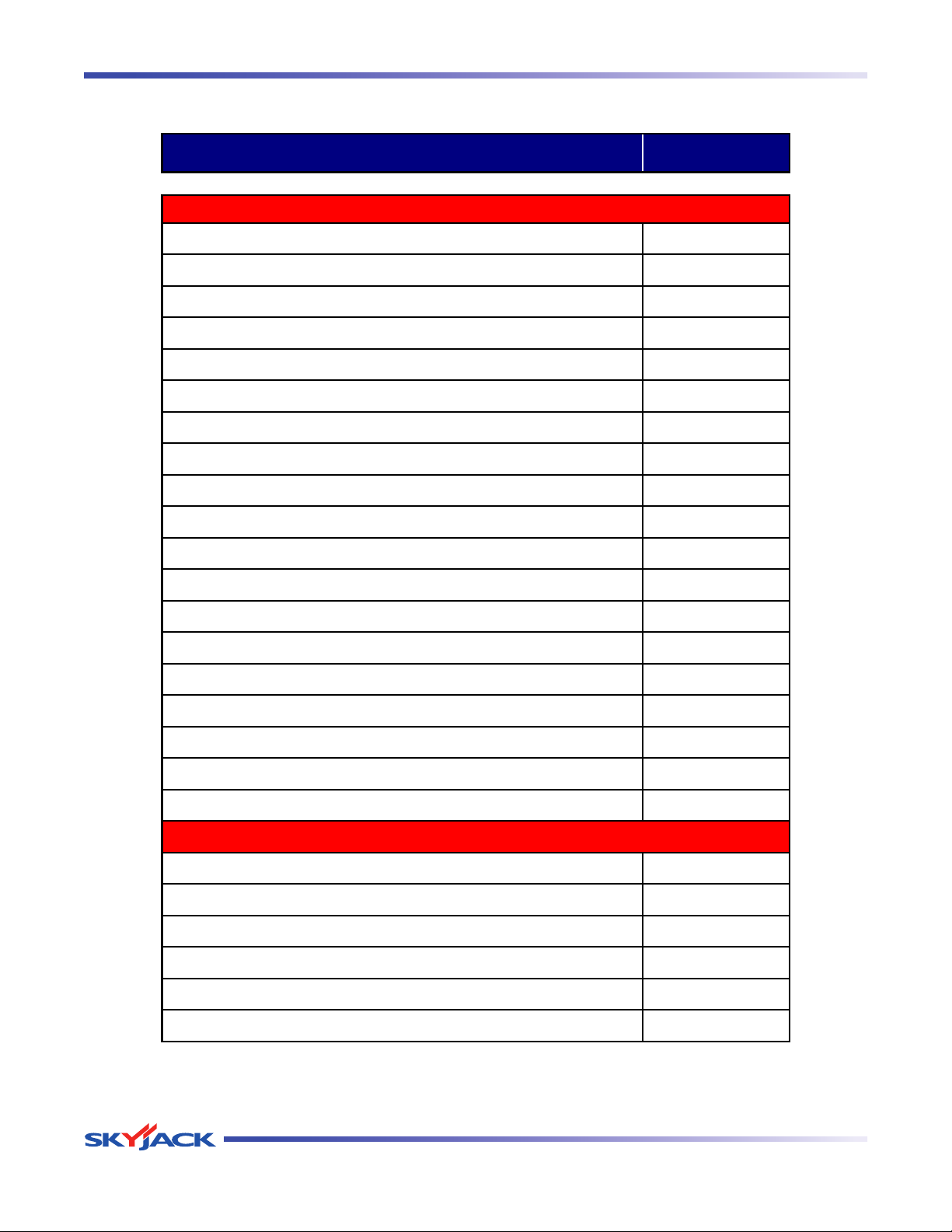
TM
Tables Section 2 - Operation
Models SJ12
Maximum drive height
Full Height
Variable speed, front two wheel hydraulic drive
*
90° steering (zero inside turning radius)
*
Dual holding brakes
*
Proportional controls
*
24V DC power source
*
Low voltage battery protection
*
Solid rubber, non-marking tires
*
Pothole protection system
*
110V AC outlet at platform with GFI
*
Tilt alarm with drive & lift cut-out
*
All motion audible alarm
*
Lanyard attachment points
*
Operator horn
*
Lift lugs/tie downs
*
Relay based control system
*
Color coded and numbered wiring system
*
Traversing platform
*
Chain entrance gate
*
Flashing light
*
AC inverter
*
Light duty pipe rack/steel stud rack
*
Tool tray
*
Fluorescent light holder
*
Full height spring hinged gate
*
265AA
O P T I O N A L E Q U I P M E N T
S T A N D A R D E Q U I P M E N T
Table 2.1 Standard and Optional Features
Page 46 December 2007
Vertical Mast Series
Page 44
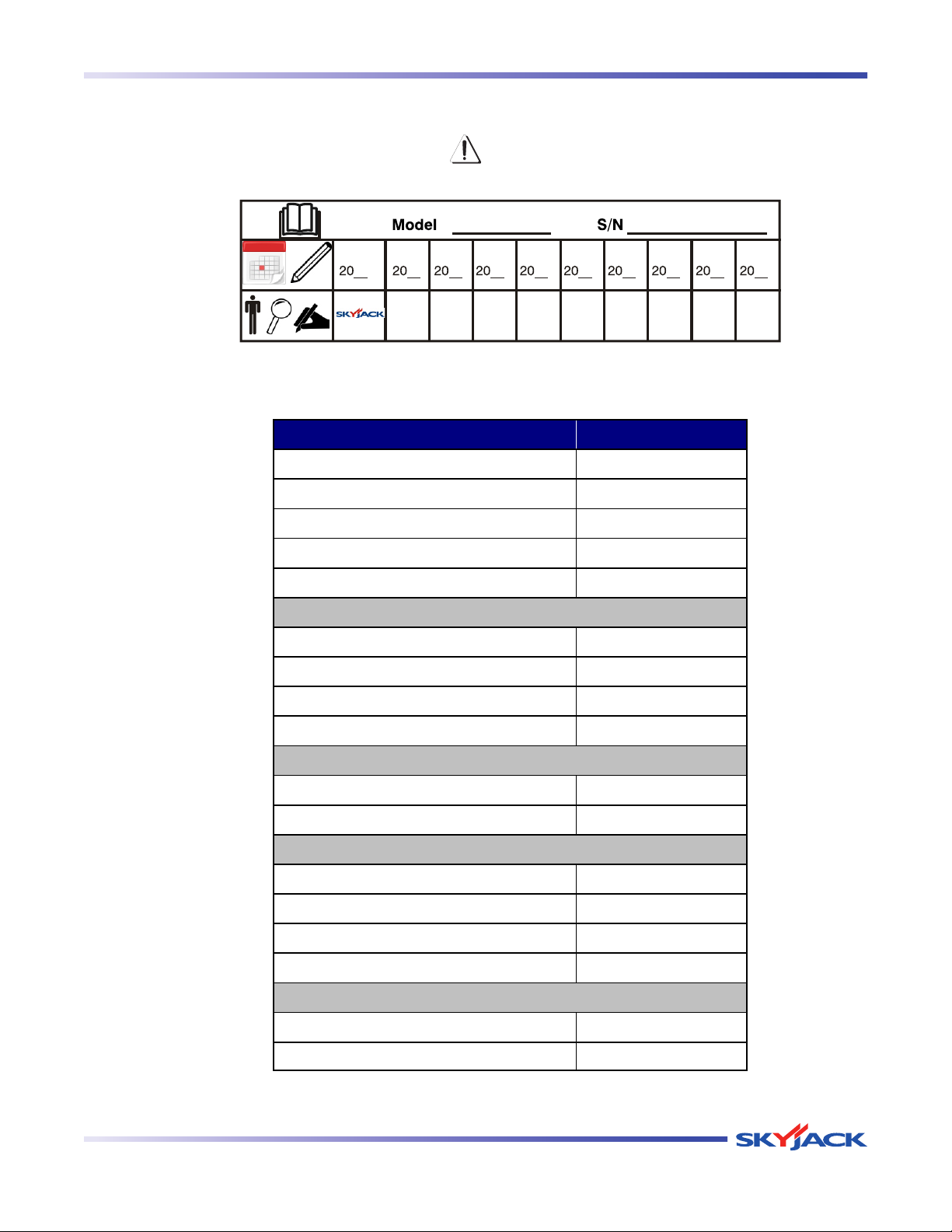
TM
Section 2 - Operation Tables
MODEL SJ12
Weight
*
1720 Ib.
Overall width
30 in.
Overall length
54 in.
Platform Size (inside)
26.5 in. x 38.5 in.
Platform translation
20 in.
Working Height
18.6 ft.
Platform Elevated Height
11.8 ft.
Stowed Height
65.5 in.
Drive Height
Full
Lift Time (Rated Load)
15.2 s
Lower Time (Rated Load)
12.1 s
Normal Drive Speed
3.0 mph
Elevated Drive Speed
0.5 mph
Gradeability (Ramp Angle)**
30% / 25%
Tires (Solid Rubber)
12 x 4 in.
Type
ATF Dexron III
Tank Capacity
1.3 gal.
266AA
* Weights are approximate; refer to serial nameplate for specific weight.
** Refer to Section 2.10 Loading/Unload for more details.
Chassis
Hydraulic Oil
Height
Standard Operating Times
Table 2.2 Owner’s Annual Inspection Record
WARNING
Do not use the aerial platform if an inspection has not been recorded in the last 13 months.
This decal must be completed, dated and signed, after each inspection time interval as stated above.
Table 2.3 Specifications and Features
Vertical Mast Series
December 2007 Page 47
Page 45
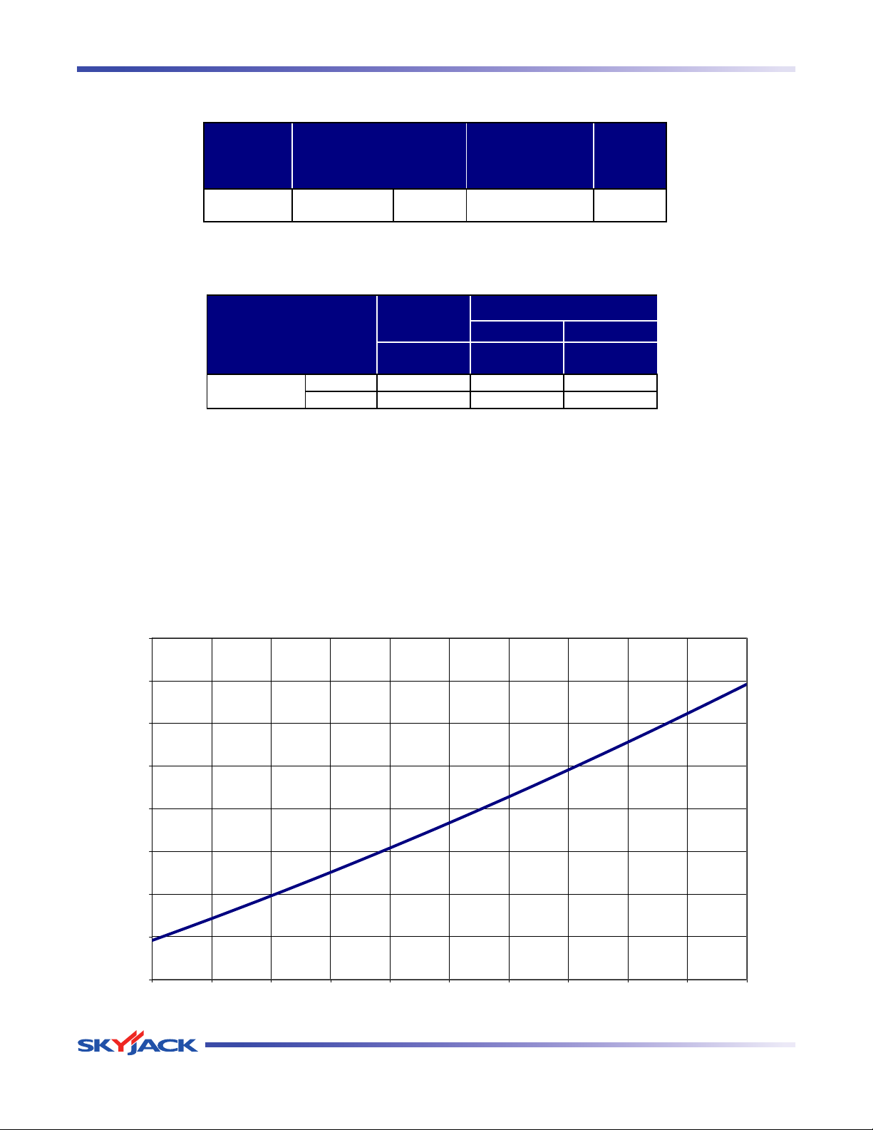
TM
Tables Section 2 - Operation
SJ12
500 lb. 2 Person(s) 28 mph 1.5 x 3
267AA
Tilt
Cutout
Setting
MODEL Capacity
Maximum Wind
Speed
Wheel OUP**
lb. lb. psf
min* 1720 430 150
max* 2220 880 195
268AA
*
max - Aerial platform weight + all options + full capacity
**
NOTE:
LCP - Locally Concentrated Pressure is a measure of how hard the aerial
platform presses on the areas in direct contact with the floor. The floor covering
(tile, carpet, etc.) must be able to withstand more that the indicated values
above.
OUP - Overall Uniform Pressure is a measure of the average load the aerial
platform imparts on the whole surface directly underneath it. The structure of the
operating surface (beams, etc.) must be able to withstand more than the
indicated values above.
The LCP or OUP that an individual surface can withstand varies from structure
to structure and is generally determined by the engineer or architect for that
particular structure.
SJ12
min - Aerial platform weight with no options
MODEL
Total Aerial
Platform
Weight
Total Aerial Platform Load
SJ12
80
85
90
95
100
105
110
115
120
0 50 100 150 200 250 300 350 400 450 500
Load on the Platform [lb]
Locally Concentrated Pressure [psi]
Table 2.4 Maximum Platform Capacities (Evenly Distributed)
Table 2.5 Floor Loading Pressure
Page 48 December 2007
Vertical Mast Series
Page 46
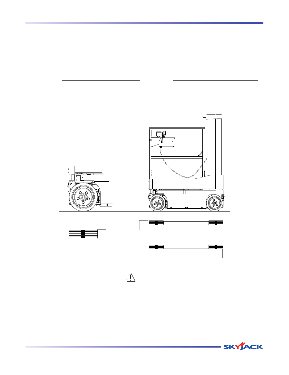
TM
Section 2 - Operation Tables
Floor Loading Pressure
Locally Concentrated Pressure (LCP): Overall Uniform Pressure (OUP):
Foot Print Area = Length x Width
Weight of Aerial Platform + Capacity
LCP = 0.4 X
Foot Print Area
Base Area = Length x Width
Weight of Aerial Platform + Capacity
OUP =
Base Area
Width
Length
Width
Length
WARNING
Intermixing tires of different types or using tires of types other than those originally supplied with
this equipment can adversely affect stability. Therefore, replace tires only with the exact original
Skyjack-approved type. Failure to operate with matched approved tires in good condition may
result in death or serious injury.
Vertical Mast Series
December 2007 Page 49
Page 47
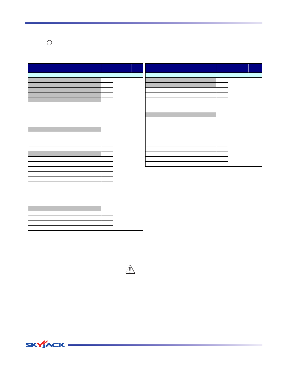
TM
Tables Section 2 - Operation
Frequency
Daily
3 months or
150 hours
Yearly
Frequency
Daily
3 months or
150 hours
Yearly
Labels A Test Main Power Disconnect Switch A
Electrical A Base Control Console A
Limit Switches A Test Base Emergency Stop A
Hydraulic A Test Off/Platform/Base Switch A
Base A Test Lower/Neutral/Raise Switch A
Main Power Disconnect Switch A Test Emergency Lowering A
Base Control Switches A Test Platform Maintenance Limit Switch A
110V Outlet Receptacle (If equipped) A Platform Control Console A
Pothole Protection Device A Test Platform Emergency Stop A
Wheel/Tire Assembly A Test Enable Trigger Switch A
Platform Assembly A Test Lift/Off/Drive Switch Off Position A
Lanyard Attachment Anchors A Test Steering A
AC Outlet (If equipped) A Test Drive Cutout Limit Switch (If equipped) A
Platform Control Console A Test Driving A
Manuals A Test Brakes A
Hydraulic/Electrical Compartment A Test Horn A
Battery A Test Platform Raising/Lowering A
Battery Charger A Test Pothole Sensor A
Main Manifolds A
259AA
Hydraulic Tank A
Hydraulic Pump and Motor A
Hydraulic Oil A
Motor Controller A
Tilt Sensor A
Pothole Protection Device A
Limit Switches A
Lifting Mechanism A
Mast Assembly A
Wear Pads A
Chains A
Cables A
A - Perform Visual and Daily Maintenance Inspections & Functions Test. Refer to Section 2.7 and Section 2.8 of this manual.
B - Perform Scheduled Maintenance Inspection. Refer to Service & Maintenance manual.
* - Maintenance must be performed only by trained and competent personnel who are familiar with mechanical procedure
s
† - Refer to Skyjack's website @ www.skyjack.com for latest service bulletins prior to performing quarterly or yearly inspection.
Visual and Daily Maintenance Inspections Function Tests
B*†
B*†
General Maintenance
Before attempting any repair work, disconnect the battery by turning the main power disconnect switch
to “ ” off position. Preventive maintenance is the easiest and least expensive type of maintenance.
Table 2.6 Maintenance and Inspection Schedule
Page 50 December 2007
Use original or equivalent to the original parts and components for the aerial platform.
WARNING
Vertical Mast Series
Page 48
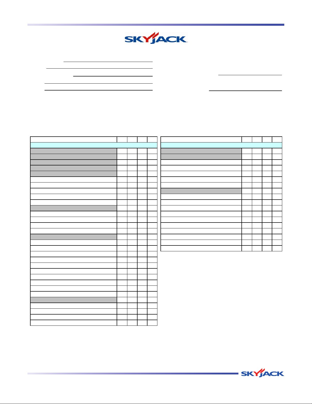
TM
Section 2 - Operation Tables
INSPECTION FRE
Q
UENCY
P
F
R
N
A
N/AP F R N/APFR
Function Tests
260AA
Chains
Cables
- NOT APPLICABLE BI-ANNUALLY
Labels
Electrical
Limit Switches
110V Outlet Receptacle (If equipped)
Hydraulic
Base
Main Power Disconnect Switch
Base Control Switches
Date:
Time:
Operator's Name (Printed):
Visual and Daily Maintenance Inspections
Operator's Signature:
A
s each item is inspected, check the appropriate box.
- PASS
- FAIL
- REPAIRED
A
NNUALLY
OPERATOR'S CHECKLIST
Each item shall be inspected using the the appropriate section of the Skyjack operating manual.
Serial Number:
Model:
Hourmeter Reading:
FREQUENTLY
DAILY
Test Platform Raising/Lowering
Test Pothole Sensor
Test Steering
Test Driving
Test Brakes
Test Horn
Lifting Mechanism
Mast Assembly
Wear Pads
Hydraulic/Electrical Compartment
Battery Charger
Main Manifolds
Hydraulic Tank
Battery
Limit Switches
Motor Controller
Test Base Emergency Stop
Test Lower/Neutral/Raise Switch
Test Off/Platform/Base Switch
Test Main Power Disconnect Switch
Base Control Console
Test Drive Cutout Limit Switch (If equipped)
Platform Assembly
Test Emergency Lowering
Test Platform Maintenance Limit Switch
Test Platform Emergency Stop
Test Enable Trigger Switch
Platform Control Console
Pothole Protection Device
Wheel/Tire Assembly
Test Lift/Off/Drive Switch Off Position
Tilt Sensor
Pothole Protection Device
Lanyard Attachment Anchors
AC Outlet (If equipped)
Platform Control Console
Manuals
Hydraulic Oil
Hydraulic Pump and Motor
Note:
Make a copy of this page or visit the Skyjack web site:
www.skyjack.com for a printable copy.
Platform Control Console
Vertical Mast Series
December 2007 Page 51
Page 49
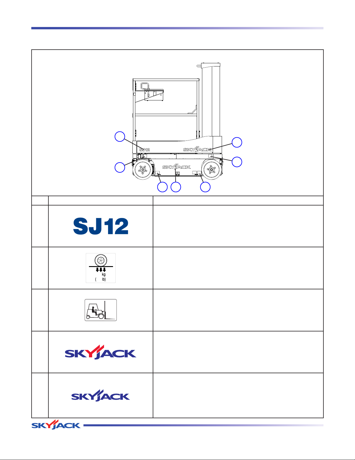
TM
Labels Section 2 - Operation
Labels - Model SJ12
Left View
1
5
2
2
4 3
3
No. Label Pictorial Description
Model Number*
1
Product Idenifiter
*Model number will vary, may not be as shown.
Wheel Load
2
Indicates rated wheel load.
Forklift Pocket
3
Insert fork fully into pocket to lift aerial platform.
Skyjack Logo
4
Small Skyjack logo - blue and red
Skyjack Logo
5
Small Skyjack logo - blue
Page 52 December 2007
Vertical Mast Series
Page 50
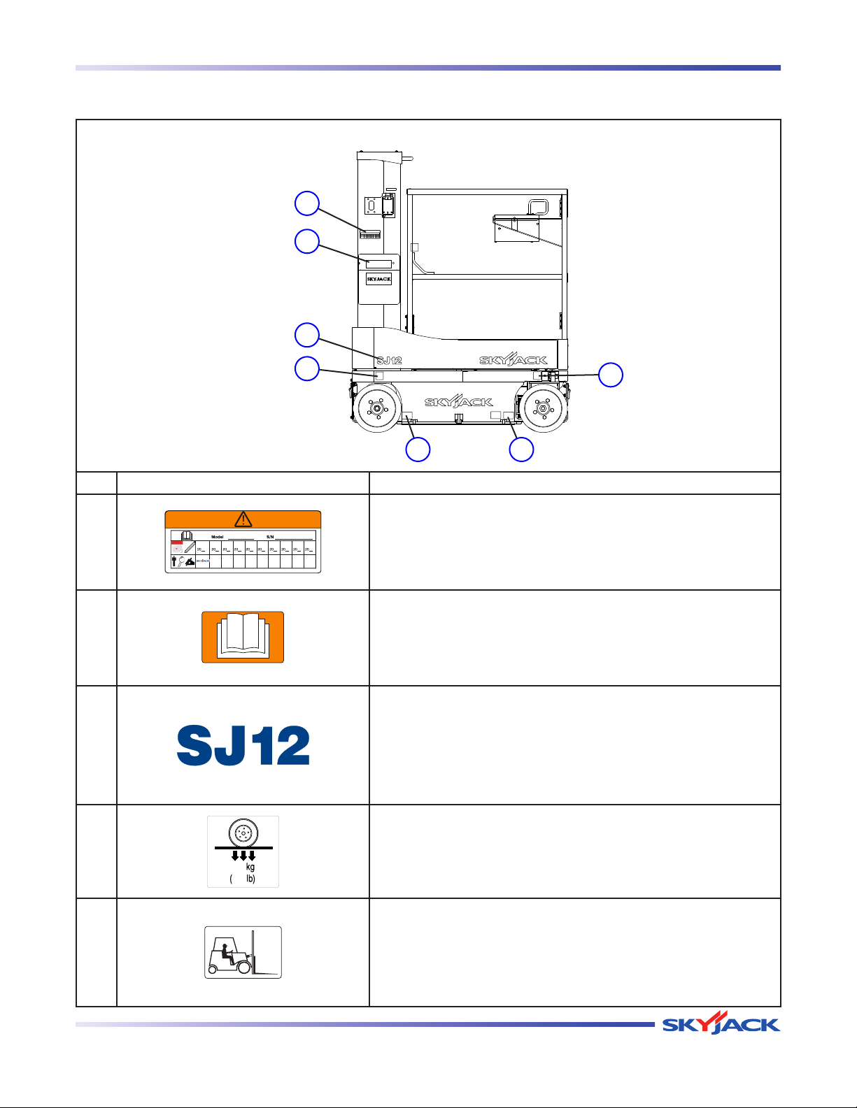
TM
Section 2 - Operation Labels
Labels - Model SJ12
Right View
1
2
3
4
55
No. Label Pictorial Description
Annual Inspection
1
Ensure that work platform has received annual inspection prior
to operation.
Manual Storage Box
2
Indicates location of operating manual.
Model Number*
Product Idenifiter
3
*Model number will vary, may not be as shown.
4
4
5
Vertical Mast Series
Wheel Load
Indicates rated wheel load.
Forklift Pocket
Insert fork fully into pocket to lift aerial platform.
December 2007 Page 53
Page 51
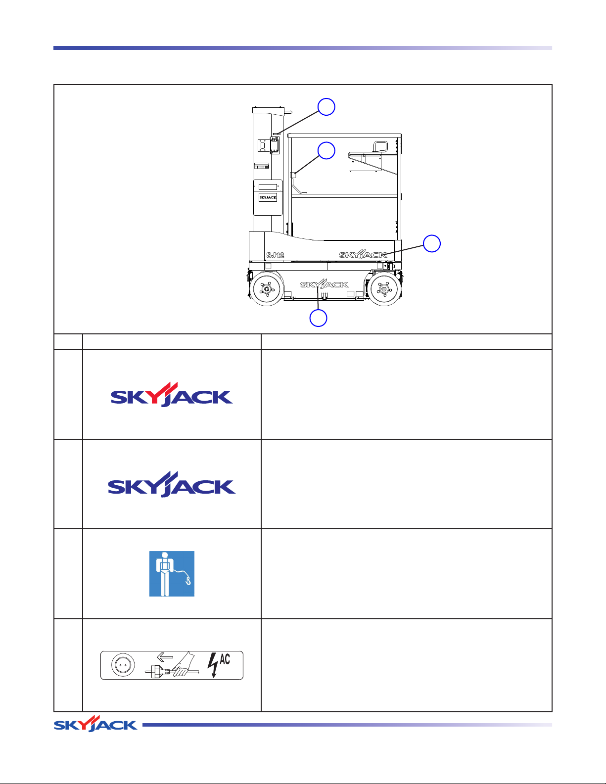
TM
Labels Section 2 - Operation
Labels - Model SJ12
Right View (Continued)
9
8
7
6
No. Label Pictorial Description
Skyjack Logo
Small Skyjack logo - blue and red
6
Skyjack Logo
Small Skyjack logo - blue
7
Lanyard Anchorage Point
Attach anchorage harness lanyard here.
8
Connect Platform AC Supply
Connect AC power supply here for platform accessory outlet.
9
Page 54 December 2007
Vertical Mast Series
Page 52
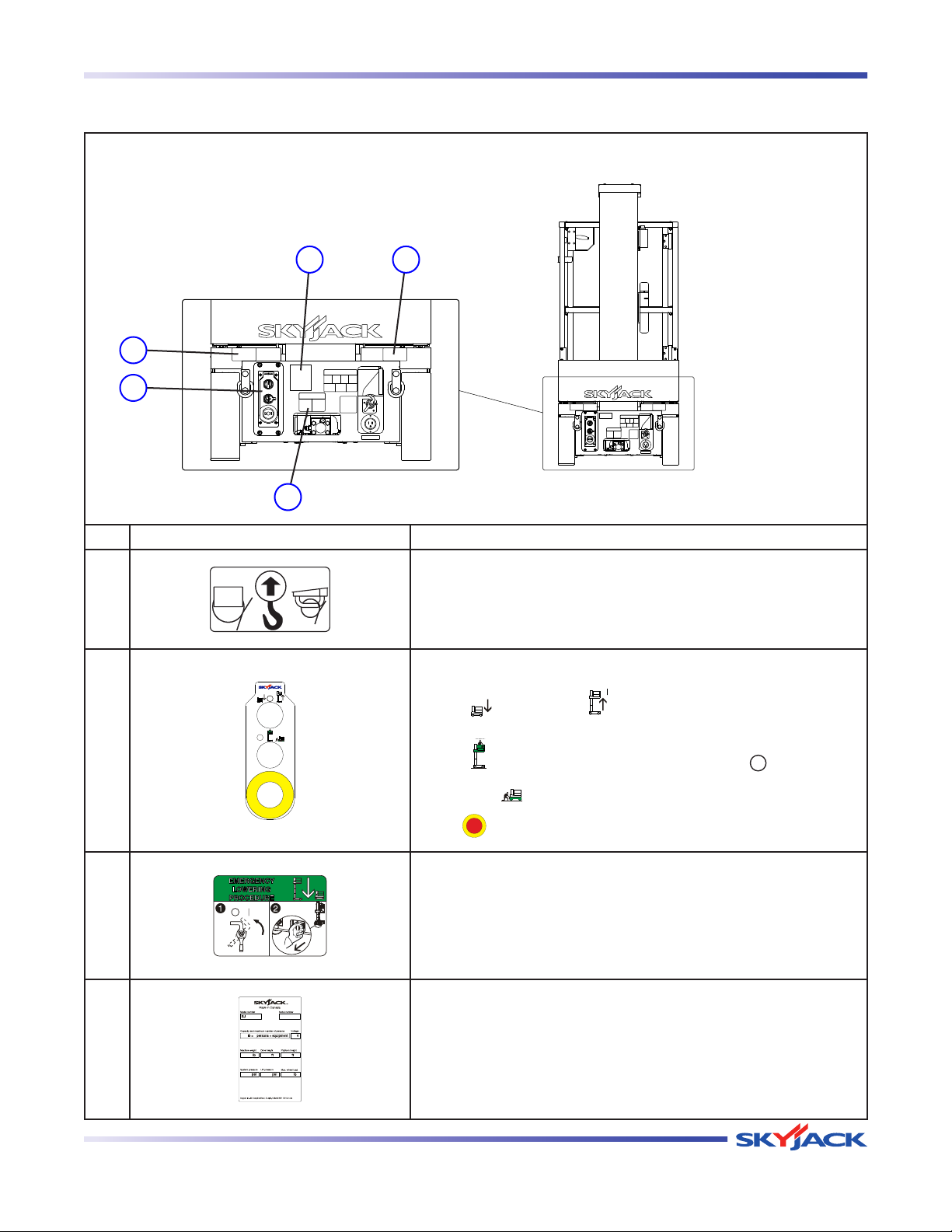
TM
Section 2 - Operation Labels
Labels - Model SJ12
Rear View
14
1
2
3
No. Label Pictorial Description
Lift and Tie Down Points
1
Only use these points for lifting or tying down.
Base Controls
Select “
” to lower or “
” raise platform.
2
Select “
controls or “
” platform to enable platform controls, “ ” off to disable
” base to enable base control console.
Push “ ” to disable controls.
Emergency Lowering Procedure
In case of emergency, follow this procedure to lower the
3
platform manually.
4
Vertical Mast Series
Serial Plate*
Product identification and specifications
*Serial plates will vary, may not be as shown.
December 2007 Page 55
Page 53
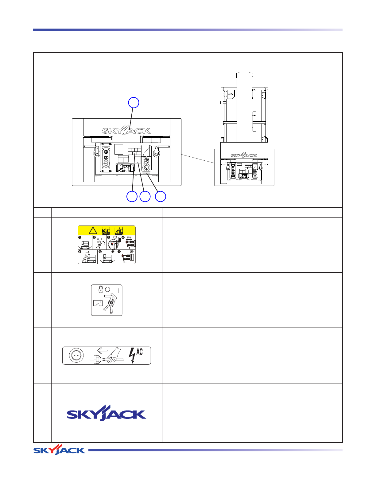
TM
Labels Section 2 - Operation
Labels - Model SJ12
Rear View (Continued)
8
5
6 7
No. Label Pictorial Description
Towing/Pushing Procedure
Follow this procedure to tow/push the aerial platform.
5
Emergency Main Power Disconnect
Rotate clockwise to turn on emergency main power; rotate
6
counterclockwise to turn off emergency main power; insert
padlock to lock in position.
Connect Platform AC Supply
Connect AC power supply here for platform accessory outlet.
7
Skyjack Logo
Small Skyjack logo - blue
8
Page 56 December 2007
Vertical Mast Series
Page 54
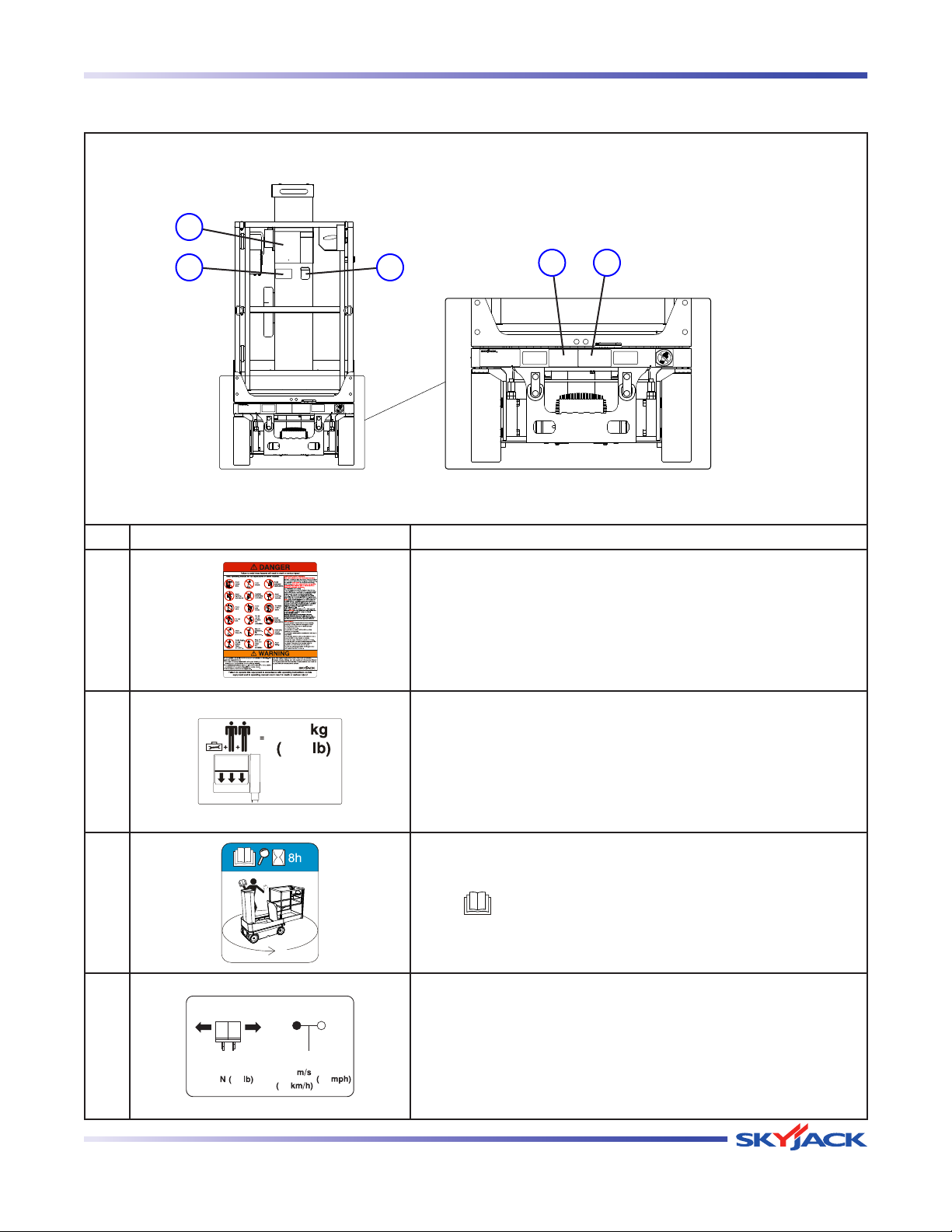
TM
Section 2 - Operation Labels
Labels - Model SJ12
Front View
1
2
3
42
No. Label Pictorial Description
Hazard Idenification
Read and understand the outlined risks associated with this
1
work platform prior to operation.
Horizontal Load Rating & Platform Capacity*
2
3
4
Vertical Mast Series
Operating with rated work load in each configuration below
indicated wind speed only.
*Label will vary, may not be as shown.
Operator Checklist
Perform check prior to use.
Read “ ” operating manual.
Horizontal Load Rating*
Apply no more than the indicated side load. Operate below
indicated wind speed only.
*Rating will change over varying units.
December 2007 Page 57
Page 55
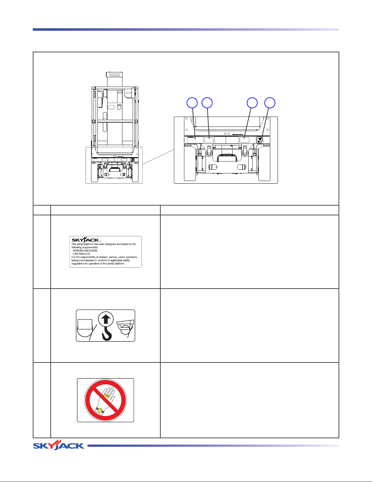
TM
Labels Section 2 - Operation
Labels - Model SJ12
Front View (Continued)
5 6 6 7
No. Label Pictorial Description
Standards Compliance
Indicates standards to which the work platform complies.
5
Lift and Tie Down Points
Only use these points for lifting or tying down.
6
No Jewelry
Caution - Do not wear jewelry.
7
Page 58 December 2007
Vertical Mast Series
Page 56
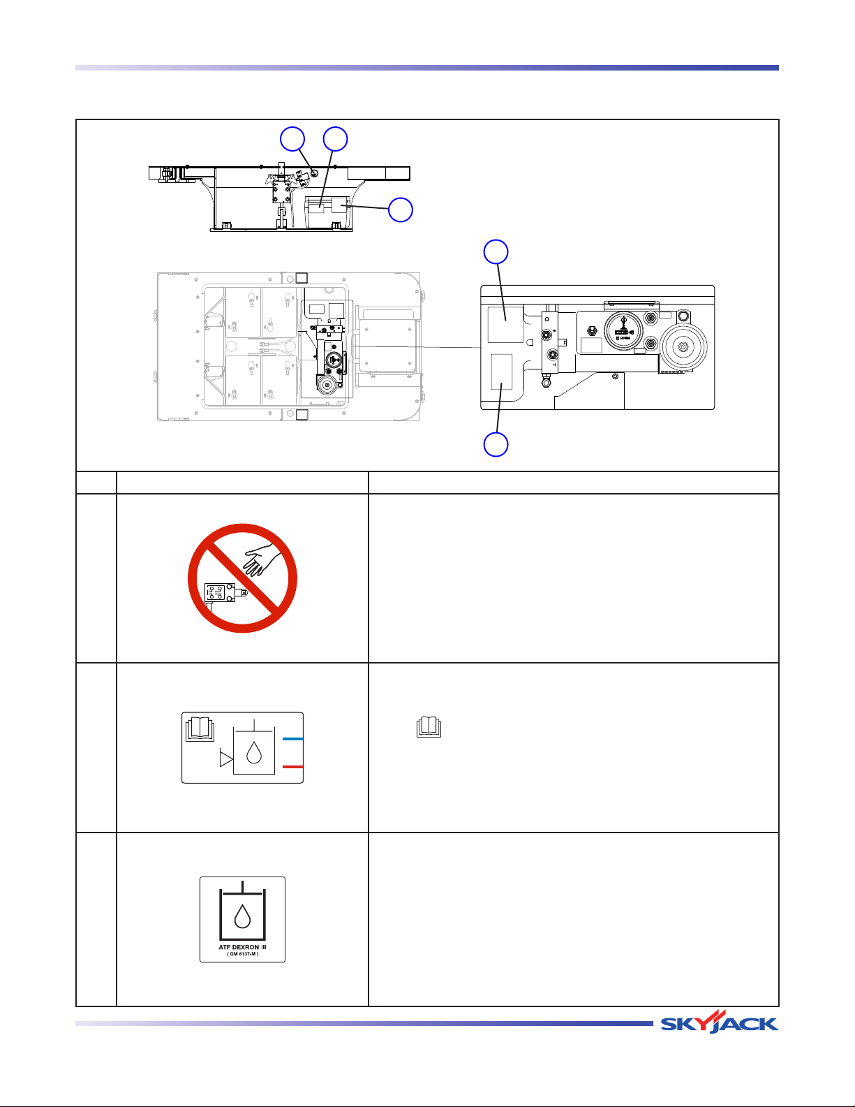
TM
Section 2 - Operation Labels
Labels - Model SJ12
Base View
1 2
3
Inside View
Top View
3
2
No. Label Pictorial Description
Warning - Do Not Alter
Aerial platform altering warning
1
Hydraulic Oil ATF Dexron III
Replace hydraulic fluid with ATF Dexron III only.
Read “ ” operating manual.
2
Hydraulic Oil ATF Dexron III
Replace hydraulic fluid with ATF Dexron III only.
3
Vertical Mast Series
December 2007 Page 59
Page 57
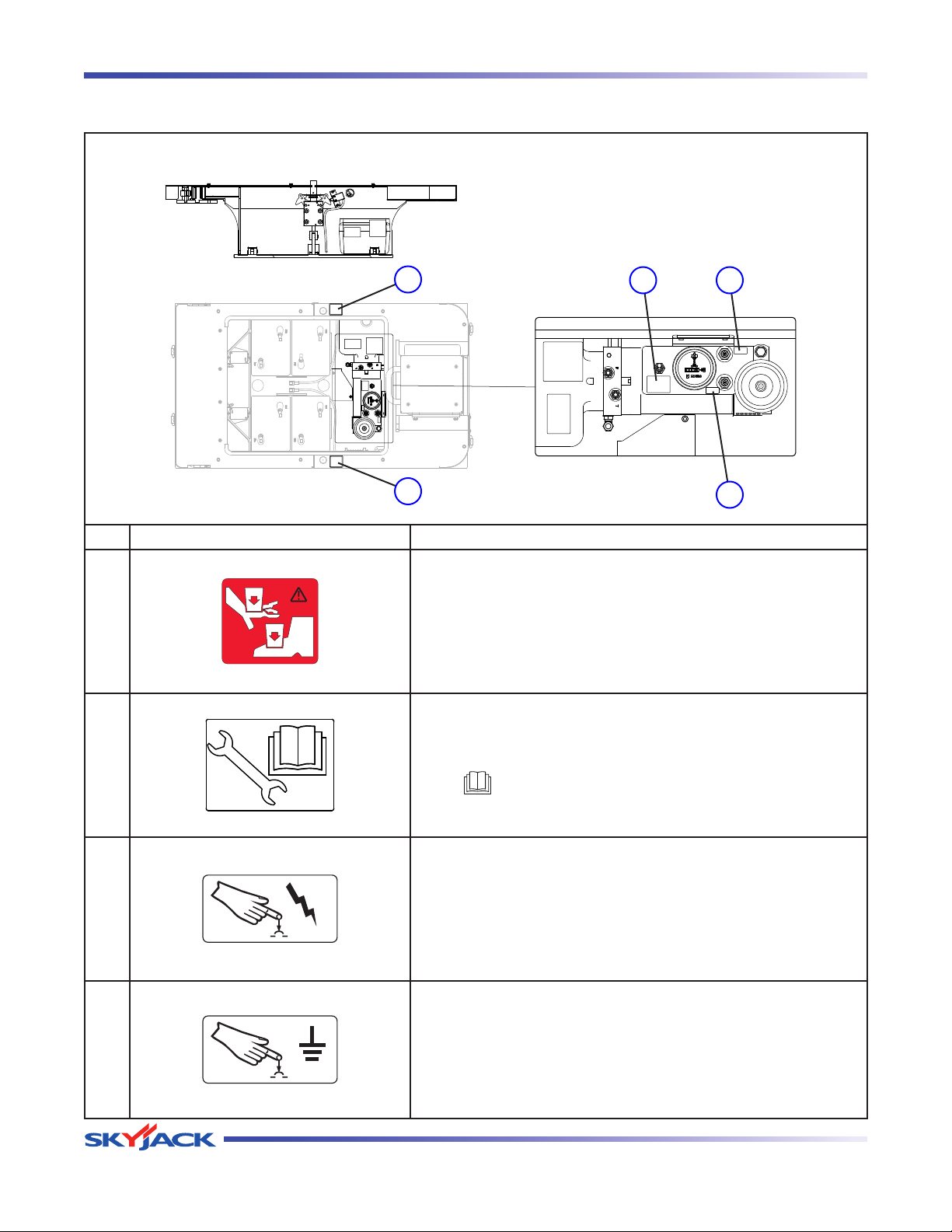
TM
Labels Section 2 - Operation
Labels - Model SJ12
Base View (Continued)
Inside View
Top View
4
5 6
4
No. Label Pictorial Description
Crushing Hazard
Danger - Crushing hazard
4
Diagnostic Switch
7
Enables hydraulic functions for maintenance service.
5
Read “ ” operating manual.
Power Circuit Breaker
Push to reset power circuit breaker.
6
Ground Circuit Breaker
Push to reset power circuit breaker.
7
Page 60 December 2007
Vertical Mast Series
Page 58
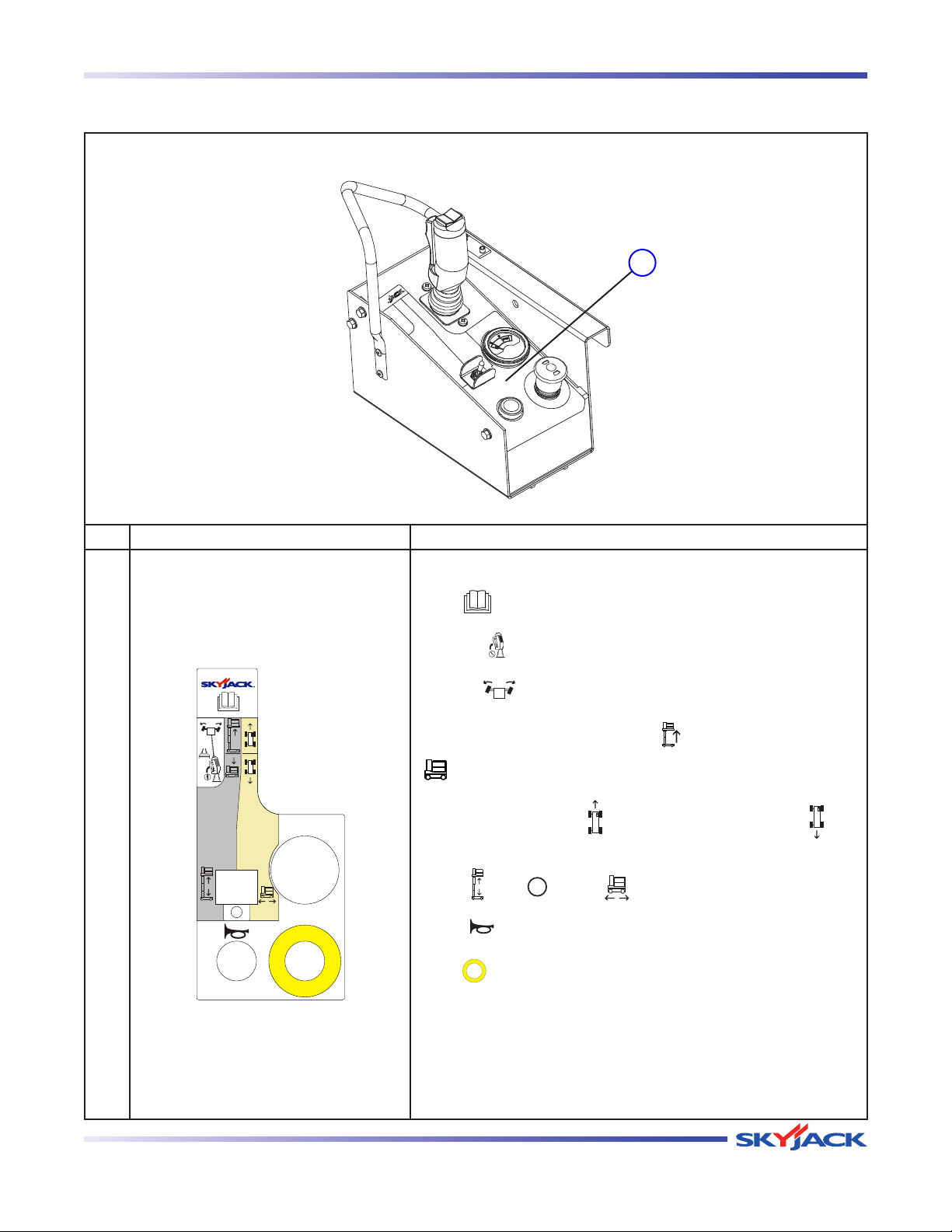
TM
Section 2 - Operation Labels
Labels - Model SJ12
Platform Control Console
1
No. Label Pictorial Description
Platform Control Console
Read “ ” operating manual.
Squeeze “ ” trigger to enable controller.
Operate “ ” rocker switch to steer.
Move controller handle forward to “
“
” lower platform.
Move controller handle “ ” forward to drive forward or “ ”
1
backward to drive reverse.
Select “ ” lift, “ ” off or “ ” drive mode.
Select “ ” to sound horn.
Push “ ” to disable controls. The operation light illuminates to
indicate upper control availability.
” raise or backward to
Vertical Mast Series
December 2007 Page 61
Page 59
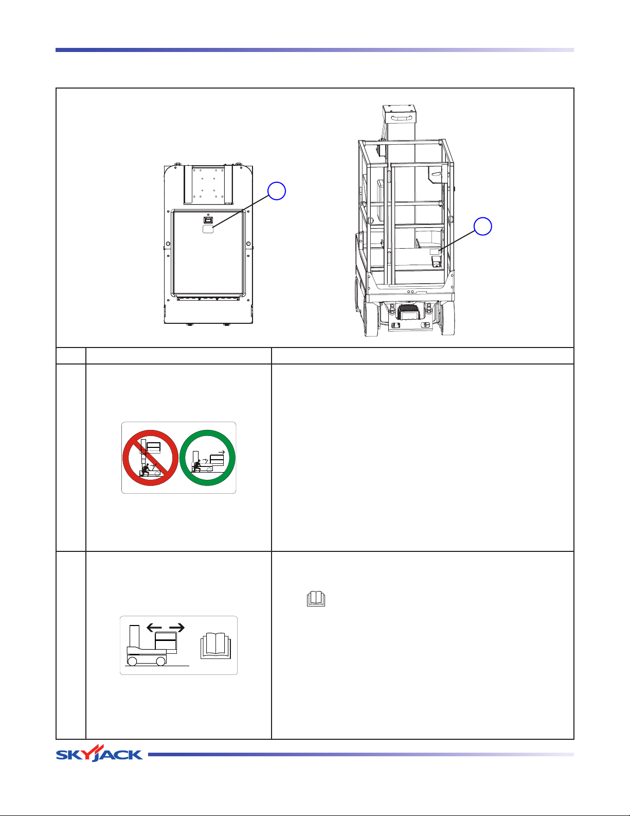
TM
Labels Section 2 - Operation
Labels - Model SJ12
Base - Top View
1
2
No. Label Pictorial Description
Warning - Do Not Open
Do not access hydraulic/electrical compartment while platform
is elevated.
1
Platform Traversing Procedure
Follow this procedure to reposition platform.
Read “ ” operating manual.
2
Page 62 December 2007
Vertical Mast Series
Page 60

Reliable lift solutions by people who care.
www.skyjack.com
 Loading...