

SkyHunter406 406 HF User Manual
OPERATING, INSTALLATION AND MAINTENANCE MANUAL
SKYHUNTER 406
TM
AF/HF
MANL:INS:SH:X:XX

MANL:INS:SH:X:XX August 8, 2013
ii
Rev 25
TABLE OF CONTENTS
TABLE OF CONTENTS ................................................................................................... ii
LIST OF TABLES ........................................................................................................ 1-1
1 System Description ....................................................................................... 1-2
1.1 Approvals ............................................................................................................ 1-3
1.1.1 Canada ............................................................................................................... 1-3
1.1.2 USA .................................................................................................................... 1-3
1.1.3 Europe ............................................................................................................... 1-3
1.2 SkyHunter 406TM ELT Installation Kits................................................................. 1-4
1.2.1 406 ELT Auto Fixed - Helicopter with High Velocity Antenna, PREWIRED
REMOTE SWITCH ............................................................................................................. 1-4
1.2.2 406 ELT Auto Fixed- Helicopter with High Velocity Antenna, NOT PREWIRED
REMOTE SWITCH ............................................................................................................. 1-4
1.2.3 406 ELT Auto Fixed - Helicopter with Whip Antenna, NOT PREWIRED REMOTE
SWITCH 1-5
1.2.4 406 ELT Auto Fixed - Helicopter with Whip Antenna, PREWIRED REMOTE
SWITCH 1-5
1.2.5 406 ELT Auto Fixed with Whip Antenna , NOT PREWIRED REMOTE SWITCH ... 1-6
1.2.6 406 ELT Auto Fixed with Whip Antenna, PREWIRED REMOTE SWITCH ............ 1-6
1.2.7 406 ELT Auto Fixed with High Velocity Antenna, NOT PRE WIRED REMOTE
SWITCH 1-7
1.2.8 406 ELT Auto Fixed with High Velocity Antenna, PREWIRED REMOTE SWITCH 1-7
1.3 Fleet Operator Options: ...................................................................................... 1-8
1.3.1 SkyKey Programmer-Blue KEYY:XXP:SH:B:TS ..................................................... 1-8
1.3.2 SkyKey Maintenance –Red KEYY:XXM:SH:R:XX ................................................. 1-8
2 Replacement Parts ........................................................................................ 2-1
2.1 Transmitter ......................................................................................................... 2-1
2.2 Battery Pack – BATT:XLS:SH:A:XX ....................................................................... 2-1
2.3 SkyHunter 406 ROD/GPS Antenna – ANNT:XVG:SH:A:XX ................................... 2-1
2.4 Whip Antenna (121.5/406 MHz) – ANNT:XXW:SH:A:XX .................................... 2-1
2.5 Remote Switch Assembly – REMT:ROC:SH:A:XX ................................................. 2-1
2.6 Mounting Bracket Kit – BRKT:KIT:SH:A:XX ......................................................... 2-1
2.7 Antenna Cable – CABL:BNC:SH:A:X2 .................................................................. 2-2
2.8 GPS Quick Disconnect Cable – CABL:GPS:SH:A:QD ............................................. 2-2

iii
2.9 SkyKey Programmer KEYY:XXP:SH:B:TS .............................................................. 2-2
2.10 SkyKey Maintenance KEYY:XXM:SH:R:XX ........................................................... 2-2
3 Design Features ............................................................................................ 3-1
3.1 Physical Features ................................................................................................ 3-1
3.2 Internal GPS Receiver ......................................................................................... 3-1
3.3 SkyKey Programmer ........................................................................................... 3-1
4 Specifications ............................................................................................... 4-1
4.1 TSO-C126a Statement ........................................................................................ 4-1
4.2 Type .................................................................................................................... 4-1
4.3 406 MHz Transmission ....................................................................................... 4-1
4.4 121.5 MHz Transmission .................................................................................... 4-1
4.5 Automatic Activation .......................................................................................... 4-2
4.6 Battery ................................................................................................................ 4-2
4.7 Housing ............................................................................................................... 4-2
4.8 Environmental Conditions .................................................................................. 4-2
4.9 Qualifications...................................................................................................... 4-2
5 Interfaces ..................................................................................................... 5-1
5.1 SMA Connector (A) ............................................................................................. 5-1
5.2 BNC Connector (B) .............................................................................................. 5-1
5.3 USB Connector (C) .............................................................................................. 5-1
5.4 High Density DB15 Connector (D) ....................................................................... 5-1
5.5 Visual Indicator Multi Colour LED (E) .................................................................. 5-1
5.6 Locking Toggle Switch (F) ................................................................................... 5-1
6 Installation ................................................................................................... 6-2
6.1 Regulatory Requirements and Guidelines .......................................................... 6-2
6.1.1 Canada – Transport Canada ............................................................................... 6-2
6.1.2 United States of America – FAA ......................................................................... 6-2
6.1.3 International ...................................................................................................... 6-2
6.2 Mounting Bracket Kit Installation ...................................................................... 6-3
6.3 ELT Installation Dimensions with Mounting Bracket .......................................... 6-5
6.4 Remote Switch Kit Installation ........................................................................... 6-6
6.4.1 Remote Switch Assemblies ................................................................................ 6-6

iv
6.4.2 SkyKey Programmer – KEYY:XXP:SH:A:XX ........................................................ 6-13
6.5 Antenna Installation ......................................................................................... 6-14
6.5.1 ROD/GPS Antenna ANNT:XVG:SH:A:XX .......................................................... 6-14
6.5.2 Whip Antenna (121.5 MHz/406 MHz) ANNT:XXW:SH:A:XX ............................ 6-14
6.5.3 Right angle antenna and gps connectors ........................................................ 6-14
6.5.4 Ground Plane Requirement (Wood/Fabric and composite aircraft) ............... 6-15
6.5.5 Ground plane sizing ......................................................................................... 6-15
6.5.6 ANNT:XVG antenna install with fabric or composite ....................................... 6-16
6.5.7 ANNT:XXW:SH:A:XX antenna install with fabric or composite ........................ 6-17
6.6 ELT Installation and Connections ..................................................................... 6-18
7 SkyHunter 406TM Operation .......................................................................... 7-1
7.1 Activation ........................................................................................................... 7-1
7.1.1 Automatic Activation ......................................................................................... 7-1
7.1.2 Manual Activation ............................................................................................. 7-1
7.2 Reset ................................................................................................................... 7-1
7.2.1 Manual Reset ..................................................................................................... 7-1
7.2.2 Remote Reset .................................................................................................... 7-1
7.3 LED Coding .......................................................................................................... 7-2
7.3.1 Self Tests ............................................................................................................ 7-2
7.3.2 ELT “ON” ............................................................................................................ 7-5
8 Maintenance ................................................................................................ 8-1
8.1 Canada ............................................................................................................... 8-1
8.2 Maintenance Steps ............................................................................................. 8-1
8.2.1 Corrosion Inspection .......................................................................................... 8-1
8.2.2 Operational Testing ........................................................................................... 8-1
8.2.3 Performance Testing ......................................................................................... 8-1
8.2.4 Measuring peak power after 3 minutes of operation ....................................... 8-1
8.2.5 Measuring the frequency after 3 minutes of operation .................................... 8-1
8.2.6 Check for proper sweep tone ............................................................................ 8-2
8.2.7 Check the 406 Coded Message .......................................................................... 8-2
8.2.8 Measuring the current draw .............................................................................. 8-2
8.2.9 Testing the G-Switch Function ........................................................................... 8-2
8.3 USA ..................................................................................................................... 8-2
8.4 International ....................................................................................................... 8-2

v
8.5 Battery Replacement .......................................................................................... 8-3
8.6 Velcro straps ...................................................................................................... 8-4
8.7 Shipping .............................................................................................................. 8-4
9 Registration .................................................................................................. 9-1
9.1 Canada ............................................................................................................... 9-1
9.2 USA ..................................................................................................................... 9-2
9.3 International ....................................................................................................... 9-2
10 Diagrams .................................................................................................... 10-1
10.1 Mounting Bracket Drilling Pattern ................................................................... 10-1
10.2 Antenna Installation Diagrams ........................................................................ 10-2
10.2.1 GPS / Rod Antenna Mounting ANNT:XVG:SH:A:XX ......................................... 10-2
10.2.2 Whip Antenna (121.5/406 MHz) ANNT:XXW:SH:A:XX .................................... 10-5
11 Notices to User ........................................................................................... 11-1
11.1 Industry Canada Approved Antennas ............................................................... 11-1
12 Revisions Table ........................................................................................... 12-1

MANL:INS:SH:X:XX August 8 ,2013
Rev 25
Table of Figures
Fig. 1 – System Description.......................................................................................................................... 1-2
Fig. 2 – SkyKey Maintenance Programmer-Red, KEYY:XXM:SH:R:XX .......................................................... 1-8
Fig. 3 - Mounting Bracket Kit, BRKT:KIT:SH:X:XX ......................................................................................... 6-4
Fig. 4 - Remote Connector and Buzzer Assembly , REMT:BUZ:SH:A:XX ................................................... 6-11
Fig. 5 – SkyKey Programmer, KEYY:XXP:SH:A:XX ....................................................................................... 6-13
Fig. 7 – Fixed ELT in Bracket ....................................................................................................................... 6-18
Fig. 8 - Mounting AF Models...................................................................................................................... 6-19
Fig. 9 - Mounting HF Models ..................................................................................................................... 6-20
Fig. 10 - Battery Cover Removal .................................................................................................................. 8-3
Fig. 11 - Mounting Bracket Drilling Pattern, BRKT:TRY:SH:X:XX ................................................................ 10-1
LIST OF TABLES
Table 1 – SkyHunter 406TM Install Kit Part Numbers ................................................................................... 1-7
Table 2 – Self Test LED Coding ..................................................................................................................... 7-2
Table 3 – Power Test Burst LED Coding ....................................................................................................... 7-3
Table 4 - ELT "ON" LED Coding .................................................................................................................... 7-5
Table 5 - Revisions ..................................................................................................................................... 12-1
1-1

MANL:INS:SH:X:XX August 8 ,2013
TYPE
Single Axis
G-Switch
5 Axis G-
Switch
Internal GPS
Receiver
AF X
X
HF X X
X
Rev 25
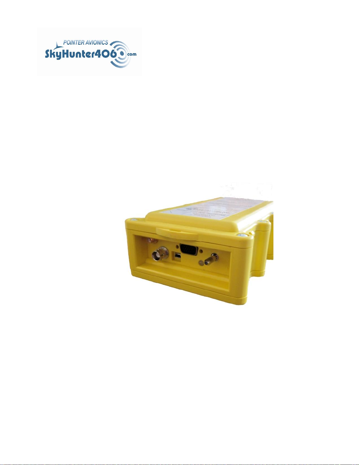
1 SYSTEM DESCRIPTION
The SkyHunter 406TM AF/HF models are of type Automatic Fixed , transmitting on 121.5/406.037
MHz and designed for use on either fixed or rotary wing aircraft. 6-position g-switch models are
also available for helicopter use, SkyHunter 406TM HF .
Fig. 1 – System Description
The entire line of SkyHunter 406TM ELT’s has been designed, tested, and certified to meet or
exceed the requirements of TSO C126a. Our SkyHunter 406TM ELT has been designed, tested,
and certified to meet the needs of both Commercial and General Aviation.
The SkyHunter 406TM incorporates an internal GPS receiver in ALL models allowing the
transmission of exact co-ordinates to the COSPAS-SARSAT satellites .
The SkyHunter 406TM can be automatically or manually activated and transmits the standard
sweep tone on the 121.5 MHz frequency for a minimum of 50 hours. Every 50 seconds of the
first 24 hours of an ELT activation a digital message is transmitted on the 406.037 MHz
frequency. The digital message will be decoded by COSPAS-SARSAT.
As a comparison, the 121.5 MHz frequency ELT’s in the past would bring search and rescue
within 20 km of the ELT. The 406.037 MHz frequency will bring search and rescue within 5 km of
the ELT. If the GPS co-ordinates are transmitted the search area will be reduced.
After an activated ELT has been detected and the position calculated the 121.5 MHz signal is
used to home in on the crash site.
The standard Remote Connector (yellow), SkyKey Programmer (blue), and Maintenance
Programmer (red) are colour coded for ease of component recognition during maintenance
procedures.
1-2

MANL:INS:SH:X:XX August 8 ,2013
Rev 25
1.1 APPROVALS
1.1.1 Canada
1.1.1.1 Transport Canada CAN-TSO-C126a
1.1.1.2 Industry Canada
1.1.2 USA
1.1.2.1 FAA TSO-C126a
1.1.3 Europe
1.1.3.1 ETSO CAN-TSO-C126a
1-3

MANL:INS:SH:X:XX August 8 ,2013
1.2.1 406 ELT Auto Fixed - Helicopter with High Velocity Antenna,
PREWIRED REMOTE SWITCH
Kit Part # SKYH:PRE:HF:K:HV
Kit Includes:
SKYH:XXE:HF:X:02 SkyHunter 406 HF Transmitter with 6 position G switch
REMT:ROC:SH:A:XX Remote Rocker Panel Switch Assembly
REMT:MCO:SH:X:XX Remote Rocker Switch Male Connector
REMT:BUZ:SH:A:PR Backshell with Cable Assembly(PREWIRED with 25 feet of cable)
BRKT:KIT:SH:A:XX Mounting Bracket
ANNT:HVG:SH:A:XX High Velocity ELT/GPS Antenna
CABL:BNC:SH:A:2X Antenna Cable
CABL:GPS:SH:A:QD Quick Disconnect GPS Cable
BATT:XLS:SH:A:XX Battery Pack
LABL:ELH:SH:X:XX ELT Located Here decal
1.2.2 406 ELT Auto Fixed- Helicopter with High Velocity Antenna,
NOT PREWIRED REMOTE SWITCH
Kit Part# SKYH:XXE:HF:K:HV
Kit Includes:
SKYH:XXE:HF:X:02 SkyHunter 406 HF Transmitter with 6 position G switch
REMT:ROC:SH:A:XX Remote Rocker Panel Switch Assembly
REMT:MCO:SH:X:XX Remote Rocker Switch Male Connector
REMT:BUZ:SH:A:XX Backshell and Buzzer Assembly(NOT PREWIRED)
BRKT:KIT:SH:A:XX Mounting Bracket
ANNT:HVG:SH:A:XX High Velocity ELT/GPS Antenna
CABL:BNC:SH:A:2X Antenna Cable
CABL:GPS:SH:A:QD Quick Disconnect GPS Cable
BATT:XLS:SH:A:XX Battery Pack
LABL:ELH:SH:X:XX "ELT LOCATED HERE" decal
Rev 25
1.2 SKYHUNTER 406
TM
ELT INSTALLATION KITS
1-4

MANL:INS:SH:X:XX August 8 ,2013
1.2.3 406 ELT Auto Fixed - Helicopter with Whip Antenna, NOT
PREWIRED REMOTE SWITCH
Kit Part# SKYH:XXE:HF:K:XW
Kit Includes:
SKYH:XXE:HF:X:02 SkyHunter 406 HF Transmitter with 6 position G switch
REMT:ROC:SH:A:XX Remote Rocker Panel Switch Assembly
REMT:MCO:SH:X:XX Remote Rocker Switch Male Connector
REMT:BUZ:SH:A:XX Backshell and buzzer assembly(NOT PREWIRED)
BRKT:KIT:SH:A:XX Mounting Bracket
ANNT:XXW:SH:A:XX SkyHunter Whip Antenna
CABL:BNC:SH:A:2X Antenna Cable
BATT:XLS:SH:A:XX Battery Pack
LABL:ELH:SH:X:XX "ELT LOCATED HERE" decal
1.2.4 406 ELT Auto Fixed - Helicopter with Whip Antenna,
PREWIRED REMOTE SWITCH
Kit Part # SKYH:PRE:SH:K:XW
Kit Includes:
SKYH:XXE:HF:X:02 SkyHunter 406 HF Transmitter with 6 position G switch
REMT:ROC:SH:A:XX Remote Rocker Panel Switch Assembly
REMT:MCO:SH:X:XX Remote Rocker Switch Male Connector
REMT:BUZ:SH:A:PR Backshell and Cable assembly (PREWIRED with 25 feet of cable)
BRKT:KIT:SH:A:XX Mounting Bracket
ANNT:XXW:SH:A:XX SkyHunter Whip Antenna
CABL:BNC:SH:A:2X Antenna Cable
BATT:XLS:SH:A:XX Battery Pack
LABL:ELH:SH:X:XX ELT Located Here decal
Rev 25
1-5

MANL:INS:SH:X:XX August 8 ,2013
1.2.5 406 ELT Auto Fixed with Whip Antenna , NOT PREWIRED
REMOTE SWITCH
Kit Part# SKYH:XXE:AF:K:XW
Kit Includes:
SKYH:XXE:AF:X:02 406 SkyHunter 406 AF Transmitter
REMT:ROC:SH:A:XX Remote Rocker Panel Switch Assembly
REMT:MCO:SH:X:XX Remote Rocker Switch Male Connector
REMT:BUZ:SH:A:XX Backshell and Buzzer Assembly(NOT PREWIRED)
BRKT:KIT:SH:A:XX Mounting Bracket
ANNT:XXW:SH:A:XX SkyHunter Whip Antenna
CABL:BNC:SH:A:2X Antenna Cable
BATT:XLS:SH:A:XX Battery Pack
LABL:ELH:SH:X:XX "ELT LOCATED HERE" decal
.
1.2.6 406 ELT Auto Fixed with Whip Antenna, PREWIRED
REMOTE SWITCH
Kit Part# SKYH:PRE:SH:K:XW
Kit Includes:
SKYH:XXE:AF:X:02 406 SkyHunter 406 AF Transmitter
REMT:ROC:SH:A:XX Remote Rocker Panel Switch Assembly
REMT:MCO:SH:X:XX Remote Rocker Switch Male Connector
REMT:BUZ:SH:A:PR Backshell with Cable Assembly(PREWIRED with 25 feet of cable)
BRKT:KIT:SH:A:XX Mounting Bracket Kit
ANNT:XXW:SH:A:XX SkyHunter Whip Antenna
CABL:BNC:SH:A:2X Antenna Cable
BATT:XLS:SH:A:XX Battery Pack
LABL:ELH:SH:X:XX ELT Located Here decal
Rev 25
1-6

MANL:INS:SH:X:XX August 8 ,2013
1.2.7 406 ELT Auto Fixed with High Velocity Antenna, NOT PRE
WIRED REMOTE SWITCH
Kit Part# SKYH:XXE:AF:K:HV
Kit Includes:
SKYH:XXE:AF:X:XX SkyHunter 406 AF Transmitter
REMT:ROC:SH:A:XX Remote Rocker Switch Assembly
REMT:MCO:SH:X:XX Remote Rocker Switch Male Connector
REMT:BUZ:SH:A:XX Backshell and Buzzer Assembly(NOT PREWIRED with 25 feet of cable)
BRKT:KIT:SH:A:XX Mounting Bracket
ANNT:HVG:SH:A:XX High Velocity ELT/GPS Antenna
CABL:GPS:SH:A:QD GPS Quick Disconnect Cable
CABL:XX2:SH:A:XX Antenna Cable
BATT:XLS:SH:A:XX Battery Pack
LABL:ELT:SH:X:XX "ELT LOCATED HERE" decal
1.2.8 406 ELT Auto Fixed with High Velocity Antenna, PREWIRED
REMOTE SWITCH
Kit Part# SKYH:PRE:SH:K:HV
Kit Included:
SKYH:XXE:AF:X:XX SkyHunter 406 AF Transmitter
REMT:ROC:SH:A:XX Remote Rocker Panel Switch Assembly
REMT:MCO:SH:X:XX Remote Rocker Switch Male Connector
REMT:BUZ:SH:A:PR Backshell with Cable Assembly(PREWIRED with 25 feet of cable)
BRKT:KIT:SH:A:XX Mounting Bracket
ANNT:HVG:SH:A:XX High Velocity ELT/GPS Antenna
CABL:GPS:SH:A:QD GPS Quick Disconnect Cable
CABL:XX2:SH:A:XX Antenna Cable
BATT:XLS:SH:A:XX Battery Pack
LABL:ELT:SH:X:XX ELT Located Here Decal
Rev 25
Table 1 – SkyHunter 406TM Install Kit Part Numbers
1-7
MANL:INS:SH:X:XX August 8 ,2013
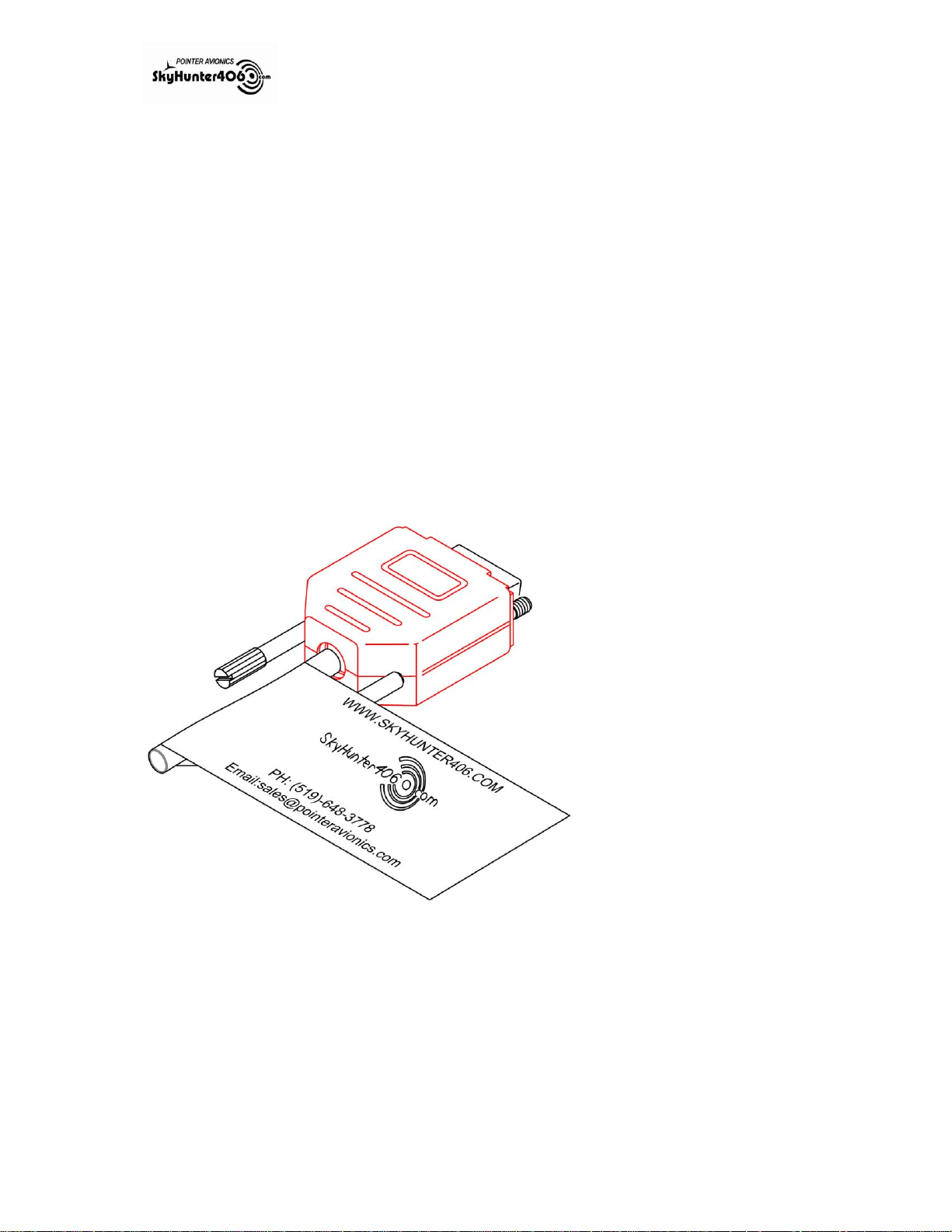
Fig. 2 – SkyKey Maintenance Programmer-Red,
KEYY:XXM:SH:R:XX
Rev 25
1.3 FLEET OPERATOR OPTIONS:
1.3.1 SkyKey Programmer-Blue KEYY:XXP:SH:B:TS
SkyKey Programmer for Fleet Operators, installed in each aircraft and programmed with specific
Aircraft information so that an alternate ELT can be placed on board reducing “down time” for
aircraft. The SkyKey is blue to indicate the additional capabilities it has when used to connect
the Remote Rocker Switch to the Skyhunter 406TM.
1.3.2 SkyKey Maintenance –Red KEYY:XXM:SH:R:XX
SkyKey Maintenance Programmer is used to return the SkyHunter 406
settings. After using a SkyKey Maintenance Programmer, the ELT will have to be reprogrammed. The Maintenance Programmer is red to denote that it will remove the aircraft ID
if attached to the SkyHunter 406TM.
TM
ELT back to default
1-8

MANL:INS:SH:X:XX August 8 ,2013
Rev 25
2 REPLACEMENT PARTS
2.1 TRANSMITTER
The SkyHunter 406TM AF and SkyHunter 406TM HF models are designed to be installed on board
aircraft and transmit on 2 frequencies. The 406.037 MHz frequency is used to transmit location
and aircraft identification and the 121.5 MHz frequency is used in the final stage of rescue to
narrow the location of the distressed aircraft during SAR efforts.
2.2 BATTERY PACK – BATT:XLS:SH:A:XX
The 5 Volt Non-Rechargeable battery pack is comprised of 4 “D” Cell Li-SO2 batteries which have
an operational life of 5 years before needing replacement.
2.3 SKYHUNTER 406 ROD/GPS ANTENNA – ANNT:XVG:SH:A:XX
This ROD/GPS antenna is rated for 600 knots and works with all SkyHunter406 ELT installation
kits. The antennas has a built in GPS receiving antenna. The antenna transmits on the 121.5 MHz
and 406.037 MHz frequencies .
2.4 WHIP ANTENNA (121.5/406 MHZ) – ANNT:XXW:SH:A:XX
The whip Antenna is designed to allow a simpler mounting option. This antenna transmits on
both 121.5 and 406 MHz frequencies. It requires only one hole for mounting. Note : The Whip
antenna does NOT provide the COSPAS-SARSAT Type approved GPS positioning since the whip
antenna does not have a built in GPS antenna. The internal GPS antenna of the ELT MAY work
depending on the aircraft fuselage material when mounted inside the aircraft.
2.5 REMOTE SWITCH ASSEMBLY – REMT:ROC:SH:A:XX
The Remote Switch Assembly contains an HD DB15 yellow connector housing with an externally
mounted audible indicator. The assembly comes complete with a panel mount rocker switch for
the cockpit .
The rocker panel switch has 3 positions “ON”/”ARM”/”RESET” with a light to indicate activation
and error codes during a self test. It is attached to the ELT via an HD DB15 connector using a 5
(4 wire + shield) conductor cable.
2.6 MOUNTING BRACKET KIT – BRKT:KIT:SH:A:XX
The bracket should be mounted near the tail of the aircraft and comes with a Velcro® Strap to
securely contain the SkyHunter 406TM ELT in its bracket.
2-1

MANL:INS:SH:X:XX August 8 ,2013
Rev 25
2.7 ANTENNA CABLE – CABL:BNC:SH:A:X2
An RG 400 cable with BNC ends attaches the Antenna to the ELT. The cable will have a length of
2 meters (approx. 6 feet).
2.8 GPS QUICK DISCONNECT CABLE – CABL:GPS:SH:A:QD
This RG 400 cable with SMA ends will allow the ELT to be attached to the GPS antenna.
2.9 SKYKEY PROGRAMMER KEYY:XXP:SH:B:TS
SkyKey Programmer for Fleet Operators, installed in each aircraft and programmed with specific
ELT and Aircraft information so that an alternate ELT can be placed on board reducing “down
time” for aircraft. The SkyKey is blue to indicate the additional capabilities it has when used to
connect the Remote Switch to the Skyhunter 406TM.
2.10 SKYKEY MAINTENANCE KEYY:XXM:SH:R:XX
SkyKey Maintenance Programmer is used to return the SkyHunter 406
settings. After using a SkyKey Maintenance Programmer, the ELT will have to be reprogrammed. The Maintenance Programmer is red to denote that it will remove the aircraft ID
if attached to the SkyHunter 406TM.
TM
ELT back to default
2-2

MANL:INS:SH:X:XX August 8 ,2013
Rev 25
3 DESIGN FEATURES
3.1 PHYSICAL FEATURES
The SkyHunter 406TM models are constructed of durable plastic, with round edges that can be
easily grasped by one hand. The Velcro® strap is simple and easy to remove for maintenance or
portability.
3.2 INTERNAL GPS RECEIVER
All SkyHunter 406TM models have been fitted with a GPS receiver which, when accompanied
with the external GPS antenna will allow accurate tracking without interfacing with an onboard
NAV system.
3.3 SKYKEY PROGRAMMER
The SkyKey Programmer enables aircraft registration information to be stored with the aircraft.
Upon SkyHunter 406TM ELT installation the registration information that is stored in the SkyKey
can be transferred to ELT memory.
3-1

MANL:INS:SH:X:XX August 8 ,2013
Rev 25
4 SPECIFICATIONS
4.1 TSO-C126A STATEMENT
“The conditions and tests for TSO approval of this article are minimum performance standards.
Those installing this article, on or in a specific type or class of aircraft, must determine that the
aircraft installation conditions are within the TSO standards. TSO articles must have separate
approval for installation in an aircraft. The article may be installed only according to 14 CFR part
43 or the applicable airworthiness requirements.”
4.2 TYPE
2 frequency ELT (121.5 MHz and 406.037 MHz)
Automatic Fixed
COSPAS-SARSAT Category 1 (-40 C to +55 C)
4.3 406 MHZ TRANSMISSION
Frequency: 406.037 MHz +/- 1 kHz
Output power: 5 W (37dbm +/- 2dbm)
Modulation Type: Bi Phase L Transmission (16K0G1D)
Transmission duration: 520 ms
Autonomy: 24 Hrs at -40 C
4.4 121.5 MHZ TRANSMISSION
Frequency: 121.5 MHz +/- 6 kHz
Output Power: 50mW (17dbm) minimum
Modulation Type: 3K20A3X
Modulation rate: 85% - 100 %
Frequency of the modulation signal: 1420 Hz to 490 Hz with decreasing sweep
Autonomy: 50 hours at -40 C
4-1
 Loading...