

Page 1

User Manual
By Mobilicom
Page 2

SkyHopper PRO
www.skyhopper.biz
Specications may be subject to change at any time.
Page 3

Notice
This manual contains information that is proprietary to Mobilicom Ltd.
No part of this publication may be reproduced in any form whatsoever without prior written approval by Mobilicom.
License Terms
Mobilicom hereby grants a non-exclusive, nontransferable worldwide license to the licensee of this software product to use the
SkyHopper PRO Graphical User Interface (GUI), in object code only for the sole and internal purpose of conguring, monitoring
and managing Mobilicom’s SkyHopper PRO.
Warranty
Mobilicom does not warrant that this software product is free from errors and/or will run properly on all computer hardware and/
or operating systems. Mobilicom does not warrant that this software will operate in the combinations that may be selected for
use by end users or that the operation of this software product will be uninterrupted or error free.
Limitation of Liability
Mobilicom’s cumulative liability to you or any other party for any loss or damage resulting from any claims, demands, or actions
arising out of, or relating to, this agreement and the Web GUI shall not exceed the sum paid to Mobilicom for the purchase of the
Web GUI. In no event shall Mobilicom be liable for any indirect, incidental, consequential, special or exemplary damages or lost
prots, even if Mobilicom has been advised of the possibility of such damages.
This agreement shall be construed and governed in accordance with the laws of the State of Israel.
Page 4

Contents
1 ABBREVIATION LIST ...........................................................................................................................................................................5
2 OVERVIEW .......................................................................................................................................................................................... 7
2.1 Network Topologies and Applications..............................................................................................................................................7
2.1.1 Point-to-Point (PTP) ................................................................................................................................................................7
2.2 SkyHopper PRO Main Features ......................................................................................................................................................7
2.3 Packets supported by the SkyHopper PRO network ......................................................................................................................8
3 PHYSICAL DESCRIPTION ..................................................................................................................................................................8
3.1 Front View Connectors .................................................................................................................................................................... 8
3.2 Unit Cables: Type & Usage ..............................................................................................................................................................8
4 MECHANICAL SPECIFICATIONS ........................................................................................................................................................ 9
5 TECHNICAL SPECIFICATIONS ........................................................................................................................................................... 9
5.1 Radio and Modem Specications....................................................................................................................................................9
5.1.1 Frequency bands available: ..................................................................................................................................................... 9
5.1.2 Antennas .................................................................................................................................................................................9
5.1.3 RF Characteristics ..................................................................................................................................................................9
5.2 Power Specications ..................................................................................................................................................................... 10
5.3 Environmental Specications ........................................................................................................................................................ 10
5.4 Embedded GPS Characteristics ................................................................................................................................................... 10
6 TDMA ................................................................................................................................................................................................. 11
7 PTP (POINT-TO-POINT) .................................................................................................................................................................... 11
7.1 PTP Link Step-by-Step Conguration............................................................................................................................................ 11
7.2 SkyHopper PRO LED indicator ..................................................................................................................................................... 13
8 INSTALLATION AND SETUP ............................................................................................................................................................. 13
8.1 Package Contents ......................................................................................................................................................................... 13
8.2 Connecting the Antennas .............................................................................................................................................................. 13
8.3 Connecting the Power ................................................................................................................................................................... 13
APPENDIX A - SPECIFICATIONS.............................................................................................................................................................. 14
APPENDIX B - MECHANICAL DRAWINGS ............................................................................................................................................... 16
APPENDIX C – CONNECTORS’ PINOUT ................................................................................................................................................. 17
C.1 RS-232/1PPS ................................................................................................................................................................................ 17
C.2 Power Cable .................................................................................................................................................................................. 17
APPENDIX D – SETTING UP A PIXHAWK BASED SYSTEM ................................................................................................................... 18
D.1 SkyHopper Setup .......................................................................................................................................................................... 18
D.2 Physical connection ...................................................................................................................................................................... 18
D.3 UART to Ethernet .......................................................................................................................................................................... 18
APPENDIX E –TROUBLESHOOTING ....................................................................................................................................................... 19
Page 5

List of Figures
FIGURE 1: SKYHOPPER PRO ....................................................................................................................................................................7
FIGURE 2: ASYMMETRIC LINK CONFIGURATION .................................................................................................................................... 7
FIGURE 3: SKYHOPPER PRO FRONT VIEW .............................................................................................................................................8
FIGURE 4: SKYHOPPER PRO CONNECTOR SIDE VIEW .........................................................................................................................9
FIGURE 5: TRANSMIT FRAMES OF THE REMOTE UNIT AND CONTROLLER UNIT FROM POWER UP ............................................ 11
FIGURE 6: WEB GUI MAIN SCREEN ........................................................................................................................................................ 12
FIGURE 7: WEB GUI “ADVANCED CONFIGURATION” SCREEN ............................................................................................................. 12
List of Tables
TABLE 1: ABBREVIATION LIST ................................................................................................................................................................... 5
TABLE 2: SKYHOPPER PRO MECHANICAL SPECIFICATIONS ................................................................................................................ 9
TABLE 3: SKYHOPPER PRO POWER SPECIFICATIONS ........................................................................................................................ 10
TABLE 4: SKYHOPPER PRO ENVIRONMENTAL SPECIFICATIONS ....................................................................................................... 10
TABLE 5: EMBEDDED GPS CHARACTERISTICS OF SKYHOPPER PRO .............................................................................................. 10
Page 6

5
1 Abbreviation List
Abbreviation Syntax
BPS Bits Per Second
BW Bandwidth
CEP Circular Error Probable (Accuracy)
CINR Carrier to Interference and Noise Ratio (Signal to Noise Ratio)
CPLD Complex Programmable Logic Device
CRC Cyclic Redundancy Code
dB Decibel
dBm Power ratio indecibels of the measured power referenced to onemilliwatt
CDD Cyclic Delay Diversity
Controller Unit
A SkyHopper PRO Unit, In PTP setup, which acts as an endpoint communication unit. Typically a Ground Unit.
CTC Convolutional Turbo Code
DC Direct Current
EMI Electromagnetic Interference
ETH Ethernet
ETSI European Telecommunication Standard Institute
FAE Field Application Engineer
FCC Federal Communications Commission
FEC Forward Error Correction
FFT Fast Fourier Transform
Freq. Frequency
FW Firmware
GHz Gigahertz
GPS Global Positioning System
HD High Denition (Video)
HW Hardware
ID Identication (Number)
IP Internet Protocol
LAN Local Area Net work
L AT Latitude
LED Light Emitting Diode
LON Longitude
LOS Line-Of-Sight
mW Milliwatt
MHz Mega Hertz
MIMO Multiple-In-Multiple-Out
MRC Maximal Ratio Combining
N.C. Not Connected
OEM Original Equipment Manufacturer
OFDM Orthogonal Frequency Division Modulation
OS Operating System
PC Personal Computer
PPS Pulse Per Second
PTP Point-To-Point
PTMP Point-To-Multipoint
QAM Quadrature Amplitude Modulation
QPSK Quadrature Phase Shift Keying (modulation)
Page 7

6
Remote Unit
A SkyHopper PRO unit, in PTP setup, which acts as an end point communication unit that
distributes clocks in the system. Typically the Aerial Unit.
RF Radio Frequency
RMS Root Mean Square (Average)
RSSI Receiver Signal Strength Indication
Rx Receive
SBAS Satellite Based Augmentation System
SDR Software Dened Radio
SW Software
TDD Time Division Duplexing
TDMA Time Division Multiple Access
Tx Transmit
UAV Unmanned Aerial Vehicle
UGV Unmanned Ground Vehicle
VLAN Virtual LAN
VPN Virtual Private Network
Table 1: Abbreviation List
Abbreviation List continued
Page 8
7
2 Overview
The SkyHopper PRO offers a bi-directional Data Link speci cally designed for commercial and industrial drones, and provides the
best solution for eet management and autonomous UAV systems. By employing leading wireless technologies, SkyHopper PRO
delivers long range and Non-Line of Sight (N-LOS) communication that supports broadcast, multicast and unicast transmission
modes.
SkyHopper PRO supports Point-to-Point and Point-to-Multipoint communication, thereby enabling various modes of operation
such as communication for multi-drone operations and drone communication to multiple ground units and viewers (receivers).
An additional bene t of your SkyHopper PRO is that it offers Control, Telemetry and Payload all in one RF channel. No need for
separate solutions for each, no need for excess items to weigh down your drone.
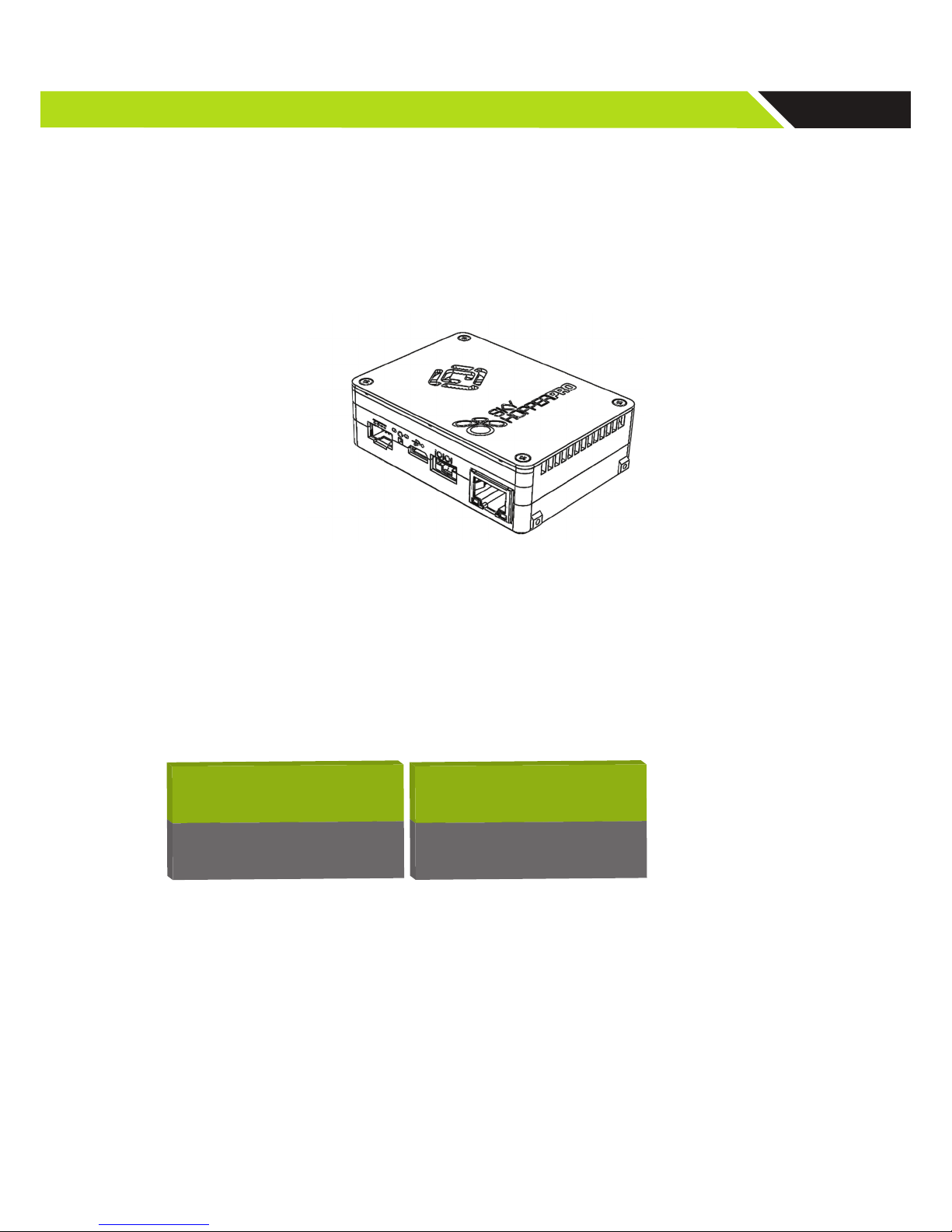
Figure 1: SkyHopper PRO
2.1. Network Topologies and Applications
2.1.1. Point-to-Point (PTP)
A Point-to-Point system includes 2 units, with the bandwidth ratio between the two units con gurable according to the application. It can be symmetric when a full duplex communication is required (50% to each unit) or asymmetric up to 10% to
one unit (Controller or Remote Unit) and 90% to the other unit (i.e. drone/robot that transmits video to the ground/controller
unit and that controls the camera).
Example for an asymmetric link: 6Mbps con guration, where 10% of available BW is allocated for uplink and 90% is allocated for downlink.
Downlink 10% = 0.6 Mbps
Downlink 90% = 5.4 Mbps
Uplink 10% = 0.6 Mbps
Uplink 90% = 5.4 Mbps
Aerial Unit
Ground Unit
Total
Network BW
6 Mbps
Figure 2: Asymmetric Link Con guration
2.2. SkyHopper PRO Main Features
SkyHopper PRO offers the following features to take your drone to new levels:
• Tremendous transmission range that exceeds 5km line-of-sight
• Relay operation for extending long range line-of-sight and overcoming dead spots in urban or industrial areas
• Non-line-of-sight (NLOS) communication by using a proprietary technology to provide a robust and clear radio signal
• Allows for a number of control stations with the same functionality to control the same drone simultaneously with seamless handover between control stations
• Supports drone communication to multiple control stations and an unlimited number of viewers (receivers)
• Real-time full HD wirelessly over the air at a Glass-to-Glass low latency via an IP camera through an Ethernet connection
• Robust security and encryption mechanisms to protect your data from potential cyberattacks
Page 9
8
• Software De ned Radio (SDR) mobile technology
• MIMO antenna processing technologies
• Scalable solution from a Point-to-Point to a Point-to-Multipoint network with relays
• High mobility with continuous transmissions up to 800km/h
• Mobile broadband network
• Small physical dimensions and very lightweight (105 gr) (portable device)
• Low power consumption (less than 10W)
• Plug-and-play installation
• Battery operated
2.3. Packets supported by the SkyHopper PRO network
The SkyHopper PRO physical link supports Ethernet (IEEE 802.3) which includes:
1. Ethernet, VLAN Services, VPN and any other Protocol over IP.
2. Real-time applications using RT Protocols such as: Voice, Video, Data
3. Broadcast, Multicast, Unicast
Any Ethernet packet received by the unit’s Ethernet port is encapsulated internally with a standard frame for transmitting via
the Data Link to the remote unit. The remote unit recovers the original Ethernet packet and forwards it to the Ethernet port.
► NOTE – The unit is similar to Ethernet layer 1 (physical layer), which makes integration with your
equipment nothing more than connecting the Ethernet cable.
3 Physical Description
3.1. Front View Connectors
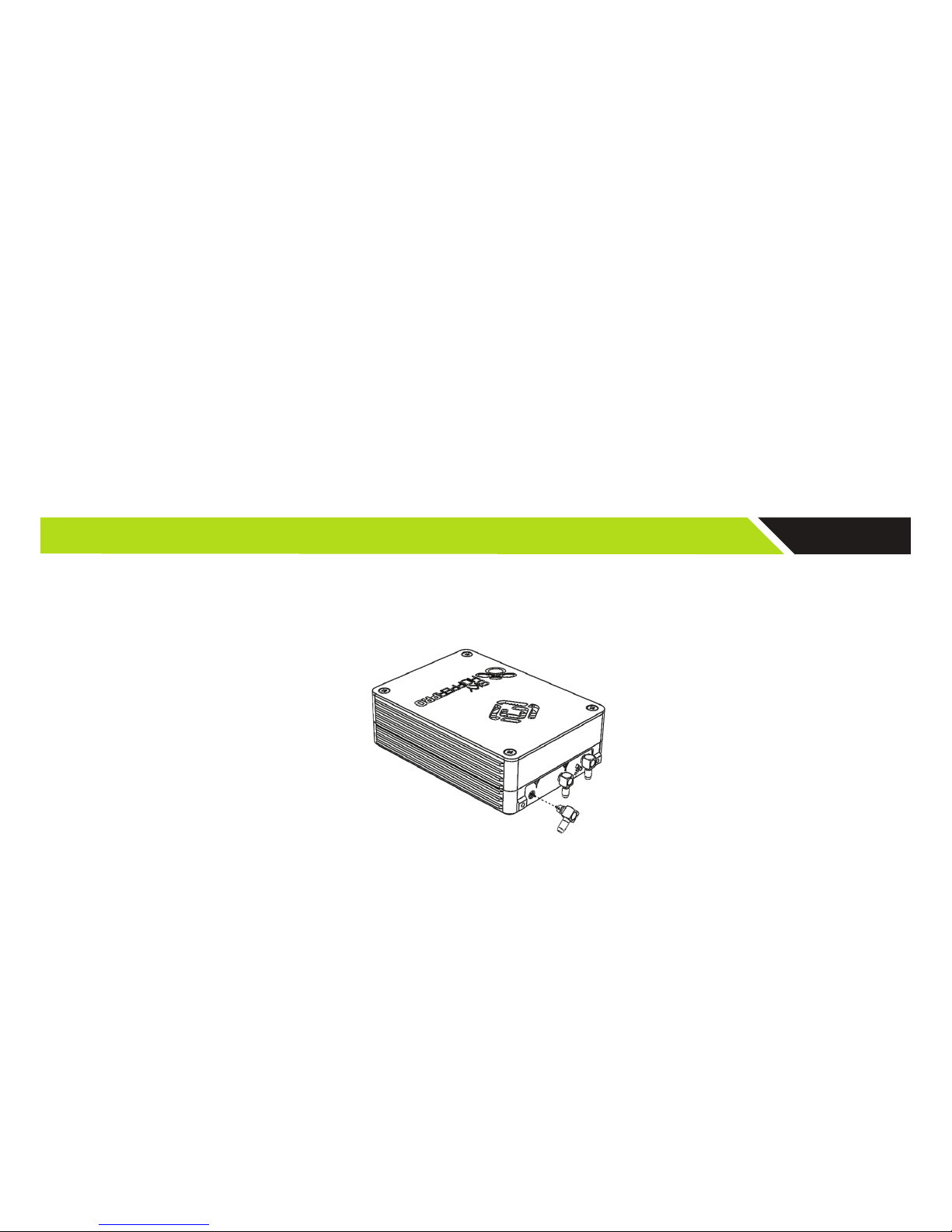
RF1: Antenna 1 Connector, MMCX/F 50 Ohm
RF2: Antenna 2 Connector, MMCX/F 50 Ohm
GPS: GPS Antenna Connector, MMCX/F
Figure 3: SkyHopper PRO Front View
3.2. Unit Cables: Type & Usage
Ethernet: Standard RJ45 connector
Serial (IOIOI):
Molex - 502380-0600
RS232 / 1PPS connector
Powe r:
ZE - ZER-04V-S
Power connectors utilizing 7-14.5VDC
! CAUTION – When SkyHopper PRO is carried by a person, environment temperature should not exceed
45°C (113°F)
► NOTE – Information about the connectors’ pin assignments are available in Appendix C – Connectors
Pinout
Page 10

9
LED: SkyHopper PRO’s LEDs indicate power on, data transmission and link status.
Figure 4: SkyHopper PRO Connector Side view
4 Mechanical Speci cations
The SkyHopper PRO unit is lightweight and has small form-factor.
Dimensions [HxWxD] (mm) [HxWxD] (inch) Weight (gr) Weight (oz)
26 x 54 x 74 1.0 x 2.1 x 2.9 105 3.7
Table 2: SkyHopper PRO Mechanical Speci cations
5 Technical Speci cations
5.1. Radio and Modem Speci cations
5.1.1. Frequency bands available:
• 2.4GHz unlicensed band
► Note: This product is con gured to operate within the FCC or CE limitations based on the country of
ordering. It is con gured within the 2.4 ISM frequency band. Mobilicom takes no responsibility should
you choose to take and/or operate this product outside of FCC or CE limits and/or in a country that does
not comply with FCC or CE regulations. Please note that SkyHopper speci cations vary based on FCC or
CE regulations.
5.1.2. Antennas
Various standard antennas can be supported using an MMCX/M connector. Some antennas with a different connector (such
as SMA) can be used with an adaptor or adaptor cable. The Ground Unit has a mounting kit supplied with an MMCX to SMA
connecting cable and SMA/M antennas.
5.1.3. RF Characteristics
• Peak output power: 2 x 0.5W per channel
• Average output power: 2 x 100mW per channel (20dBm)
• Noise Figure: 5dBm
• Transmission Power Control Range: 50dB in 1dB steps
• Radio Access Method: OFDM - TDMA
• Con guration & Diversity Support: 2X2 MIMO with MRC(RX) and CDD(TX)
• Frequency Resolution: 0.25MHz
• Channel bandwidth: Con gurable 4.2/8.4MHz
• FFT Supported: 512
• Guard band: 64 sub-carries on each side
• Total subcarriers used per symbol: 384
• Data carriers used: 336
• Pilot carriers used: 48
• Sub carrier spacing: 13KHz for 5MHz bandwidth with 5msec frame
• Modulations: QPSK, optional 16QAM
Page 11

10
• FEC methods: CTC
• FEC Ratios: ¾ , ½ , ¼
• Error Detection: CRC32
• Full TDD asymmetrical duplexing
• Flexible ratio from 1:1 to 1:9 in PTP
• Resolution of 1% between all units in multi-unit networks.
► NOTE – The wide congurable power control range enables transmitting in low Tx power when not
needed, thereby reducing power consumption.
5.2. Power Specications
SkyHopper PRO is designed to be battery operated (DC) with low power consumption. Its design allows for multiple battery
cell congurations (different voltages).
Power - LF10WBRB-4P
DC Voltage (Battery Operated) 7-14.5VDC
Power Consumption 8 Watts average use
Up to 12 Watts depending on the operational scenario (Tx:Rx Ratio)
Table 3: SkyHopper PRO Power Specications
5.3. Environmental Specications
SkyHopper PRO is designed to meet international EMI, Radio & Environmental Standards, such as wireless ETSI & FCC etc.
Environmental
Temperature Range Operating Storage
-10°C to 40°C -50°C to 85°C
Humidity 5 to 95%
Table 4: SkyHopper PRO Environmental Specications
5.4. Embedded GPS Characteristics
SkyHopper PRO has a built-in GPS receiver. In a PTP network conguration it is used for location information only (which
can be operated by the customer via the SkyHopper API). In a Multi-Unit network, it is used for synchronization and can
also be used by the customer for location purposes. SkyHopper PRO uses active GPS antennas. The power for the active
antenna is provided by the unit via the regular GPS MMCX connector.
Item Description
Receiver Type GPS L1 C/A code
Accuracy Position 2.5 m CEP
SBAS 2.0 m CEP
Acquisition Cold start: 27 s
Aided start: < 3 s
Hot start: 1 s
Sensitivity Tracking: –161 dBm
Cold start: –147 dBm
Hit start: –156 dBm
Timing Accuracy RMS 30 ns
99% < 60 ns
Granularity 21 ns
Table 5: Embedded GPS Characteristics of SkyHopper PRO
Page 12

11
6 TDMA
Time Division Multiple Access(TDMA) is achannel access methodfor shared medium networks. It allows several units to share
the samefrequency channelby dividing the signal into different time slots. The units transmit and receive on the same frequency
in a synchronized manner. Every unit transmits in its own dedicated time slots. On the other time slots said unit receives the transmission sent by the other units that are members of the same network (which are also transmitting on their own dedicated slots).
TDMA requires a synchronization system. The system is synchronized internally, externally or via GPS (synchronization varies
between topologies and method used).
The SkyHopper PRO unit uses TDMA regardless of the application type, PTP or PTMP.
7 PTP (Point-to-Point)
A PTP network is a radio link between 2 SkyHopper PRO units. The conguration (frequency and prole) of both units must be
the same with only one difference - one unit is congured as a Remote Unit while the other unit is congured as a Controller Unit.
The Remote Unit works with its internal clock and synchronizes the Controller Unit. After power-up, the Remote Unit starts transmitting regardless of link status. The Controller Unit however, does not transmit and stays in Rx mode, trying to acquire synchronization by nding a preamble (synchronization pattern). As soon as the Controller Unit recognizes the pattern, it starts to transmit
according to its allocated time slot.
The transmission bandwidth ratio is predened as part of the prole conguration. It can be symmetric when full duplex communications are required (50% to each unit) or asymmetric up to 10% to one unit (remote or controller) and 90% to the other unit.
Downlink 10% = 0.6 Mbps
Downlink 90% = 5.4 Mbps
Uplink 10% = 0.6 Mbps
Uplink 90% = 5.4 Mbps
Aerial Unit
Ground Unit
Total
Network BW
6 Mbps
TX TX TX TX
Power
up
Remote Unit
Controller Unit
t
TX TX TX
Power
up
Preamble
Received
t
Figure 5: Transmit frames of the remote unit and controller unit from Power Up
► Note: A viewer unit acts like a Controller unit but with one major change, it does not transmit
and only receives.
7. 1. PTP Link Step-by-Step Conguration
In order to build a PTP link, two SkyHopper PRO units are required. One unit acts as a remote unit, while the other as a
controller unit.
1. Connect antennas to RF1 and RF2 connectors, and power up the unit.
! CAUTION – Powering up a unit without connecting the antennas can cause irreparable damage to the unit.
2. Connect the unit to a PC using a standard Ethernet Cat 5 cable.
Page 13
12
3. Set static IP in the 192.168.131.xxx subnet
(For more information, see the Web GUI Instructional Manual).
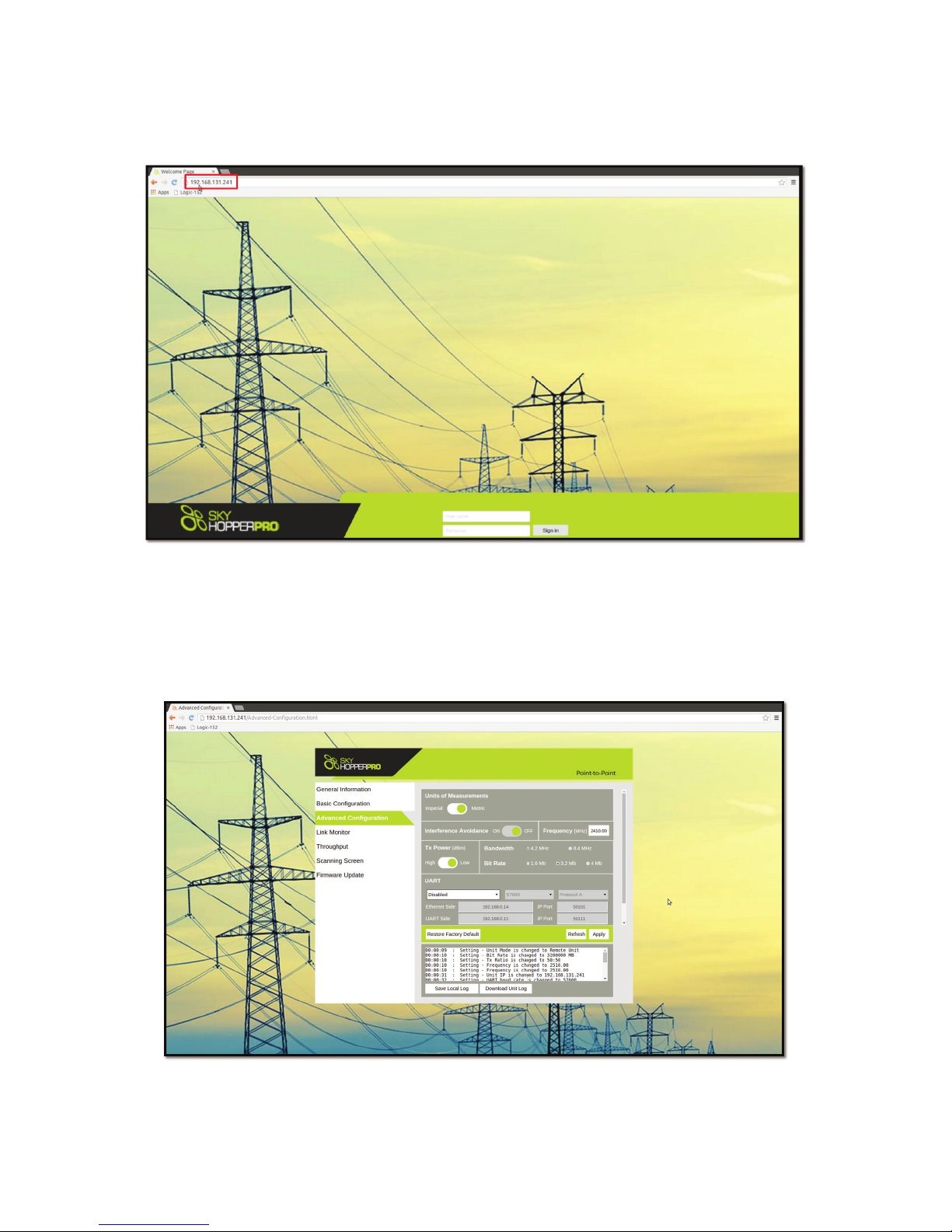
4. Using the Web GUI: Open a web browser installed on your PC / laptop (Chrome, Firefox, Internet Explorer, etc.) and
input in the address line: 192.168.131.241. That should connect you to the Web GUI interface, as shown on Figure 6:
Figure 6: Web GUI main screen
5. To change the frequency to the required frequency, click on “Advanced Con guration” (third tab on the left corner) and on the
“Frequency” line and write the desired frequency within the frequency range set in your unit.
6. Set the pro le as required (RF bandwidth, bitrate and ratio) and click on the “Apply” button as shown on Figure 7. The
unit will reboot.
7. Repeat stages 1-4 with the 2nd unit.
Figure 7: Web GUI “Advanced con guration” screen
► NOTE – A PTP setup requires 2 SkyHopper PRO units con gured with same frequency and pro le.
Page 14

13
7.2. SkyHopper PRO LED indicator
By following the LED on the unit, the power and link status can be monitored. It is described as follows:
1) ACTV LED:
A) Off – Power Down
B) On - Booting Up
C) Slow Blinking – Remote unit is transmitting, controller unit receiving (P2P search)
D) Fast Blinking – Air Link is up
1) DATA LED
A) Off – No Ethernet detected
B) On – Ethernet Cable is connected to a working device on host – No Data
C) Slow Blink – Error (synced to ACTV LED)
D) Fast Blink –Tx & Rx Air Traffic active
Should there be an error in your SkyHopper PRO unit, both the ACTV and DATA LEDs will be simultaneously slow blinking.
Link status, CINR, RSSI, throughput and unit log information is available in the Web GUI, which can be found online at www.
skyhopper.biz/prosupport.
8 Installation and Setup
8.1. Package Contents
Aerial Unit
Item Quantity
SkyHopper PRO Aerial Unit 1
2dBi Antenna MMCX 2
Power Cable 1
Telemetry Serial Data Cable 1
Ethernet Cable 1
Ground Unit
Item Quantity
SkyHopper PRO Ground Unit 1
5dBi Antenna SMA 2
Power Cable 1
Telemetry Serial Data Cable 1
Ethernet Cable 1
SMA to MMCX RF Cable 2
Bracket Mount 1
Bracket Screws 3
Tripod Knob 1
8.2. Connecting the Antennas
Antennas for installation vary in size, shape, requirements and mounting methods. The antennas should be as close to the
SkyHopper PRO as possible and can be connected to it directly.
Cables should be chosen according to their attenuation (lower attenuation gives better results) and exibility (according
to the path they pass through). Each cable should have an MMCX Male connector on the SkyHopper PRO end, and a
connector matching the antenna’s connector on the other.
8.3. Connecting the Power
SkyHopper PRO has a dual power feed enabling hot-swap battery replacement during operation.
! CAUTION – Powering up a SkyHopper PRO without connecting the antennas can cause irrepairable
damage to the unit.
Page 15

14
Appendix A - Specicaons
Radio and Modem
Frequency 2.4GHz (ISM)
900MHz (ISM) - Optional
5.8GHz (ISM) - Optional
Antenna’s Connectors MMCX (X2)
TX Power Control 50dB
RX Dynamic Range 70dB
Sensitivity Max –101dBm
Radio Access Method OFDM - TDMA
Duplexing TDD
Conguration MIMO 2X2
Channel BW 4.2MHz / 8.4MHz
Frequency Resolution 0.25MHz
Diversity Support TX & RX Diversity
FFT Supported 512
32 – 2048 upon request
FEC method Turbo Code
Modulations QPSK / 16QAM
Throughput Congurable up to 6 Mbps
Synchronization 1PPS sync input
Encryption AES-128 bit
Environmental
Temperature Range Operating Storage
-10°C to 40°C -50°C to 85°C
Humidity 5 to 95%
Interfaces
Data Ethernet, RS232
Full Ethernet Protocol Transparency IP,TCP,UDP, RTP, HTTP
Broadcast, Multicast, Unicast
Ethernet, VLAN, VPN
Serial Data RS232
USB Optional
Dimensions [HxWxD] mm [HxWxD] inch
26 x 54 x 74 1.0 x 2.1 x 2.9
Weight Grams Ounce
105 gr. 3.7 oz.
Page 16

15
Power
DC Voltage (Battery Operated) 7-14.5V DC
Power Consumption Up to 12 Watt
8W Average
Conguration and Management
Unit Monitoring Application Web-Based Application
Program Interface API, Code Lib. (Optional)
Integrated Options*
Video Encoder/Decoder H.264 very low latency HD/SD
Video Formats up to: 1920x1080p
Video Inputs / Outputs Micro HDMI (Input/Output)
Analog (Input)
Audio Inputs / Outputs Embedded Audio over HDMI, Analog
*Options at an additional cost.
Page 17
16
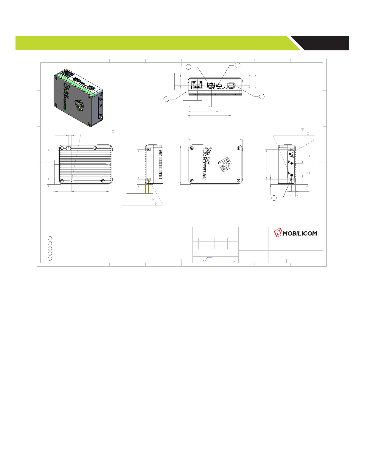
Appendix B - Mechanical Drawings
54.01
75.30
42
4.50
6.50
2 x M2x0.4 - 6H
3
MAX SCREW DEPTH
2.5
13
32.1
42.9
59.7
9.9
10.5
11.1
10.3
1
3
4
2
4.20
45 5
51.60
22.50
18.70
3 x M2.5x0.45 - 6H
3.50
42
28.9
5.2
12.8
16.1
6.50
4.50
M2x0.4 - 6H
3
MAX SCREW DEPTH
2.5
3 TYP. 3
5
NOTES:
1. APPLICABLE STANDARDS / SPECIFICATIONS:
ASME Y14.5M-1994, DIMENSIONS AND TOLERANCES.
ASME Y14.38, ABBREVIATIONS.
ASME Y14.16aM OR Y14.6, SCREW THREADS.
2. THE PART AND FINISH SHOULD BE COMPLIANCE WITH THE "EUROPEAN DIRECTIVE FOR RESTRICTIONS OF
THE USE OF CERTIAN HAZARDOUS SUBSTANCES IN ELECTRONIC EQUIPMENT" (RoHS DIRECTIVE 2002/95/EC).
1
CONNECTOR: CAT5, RECEPTACLE
2
CONNECTOR: MOLEX, CLICK MATE SERIES, 6 PINS, RECEPTACLE (P/N: 5023860670)
3
CONNECTOR: MOLEX, MICRO USB, 5 PINS, RECEPTACLE (P/N: 476100001)
4
CONNECTOR: JST, ZE SERIES, 4 PINS, MALE (P/N: 5023860670)
5
CONNECTOR: MCX SERIES, RECEPTACLE
X3
8 7
A
B
23456 1
578 246 13
E
D
C
F F
D
B
A
E
C
DRAWN
APPV'D
FINISH:
DEBURR & BREAK SHARP EDGES
NAME
SIGNATURE
DATE
MATERIAL:
THE INFORMATION CONTAINED IN THIS DRAWING IS THE
SOLE PROPERTY OF MOBILICOM. ANY REPRODUCTION IN
PART OR WHOLE WITHOUT THE WRITTEN PERMISSION OF
MOBILICOM IS PROHIBITED.
REVISION:
TITLE:
DWG NO.
SCALE:1:1
SHEET 1 OF 1
A3
FIRST ANGLE PROJECTION
ILAN B.
1/11/2017
05-0007-00
SKY HOPPER PRO UNIT
INTERFACE CONTROL
A-02
SIZE:
1/11/2017
ILAN B.
UNLESS OTHERWISE SPECIFIED
UNITS:
GENERAL
SURFACE FINISH:
LINEAR:
ANGULAR:
GENERAL TOLERANCES:
MM
Ra 1.6
Page 18
17
Appendix C – Connectors’ Pinout
C.1. RS-232/1PPS
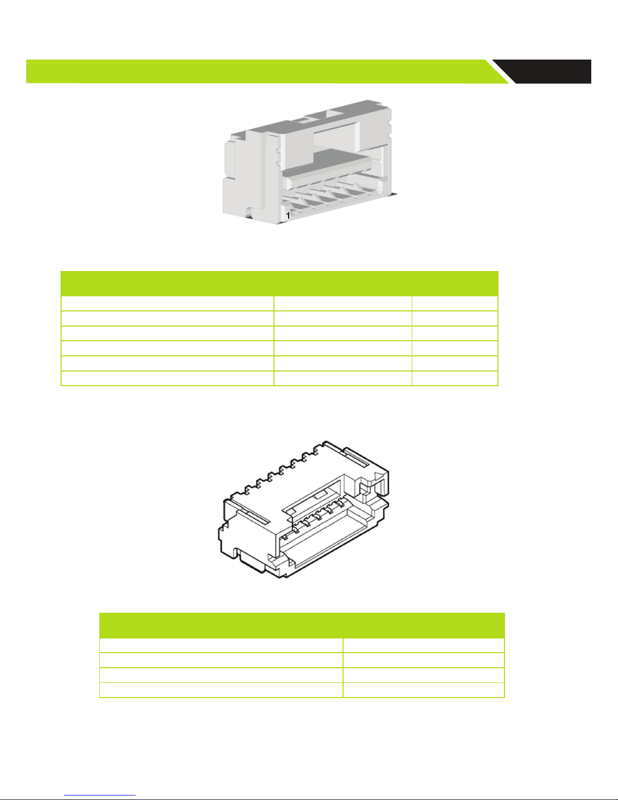
Figure 8: RS232/1PPS connector (IOIOI) (SkyHopper PRO side)
SkyHopper PRO
Housing P/N: 502380-0600Pins P/N: 502381-0 000
Name Description
1 N/A
2 RS232 out D9 Pin 2
3 N/A
4 RS232 in D9 Pin 3
5 GND
6 1PPS In
Table 6: RS232/1PPS connector pinout (IOIOI)
C.2. Power Cable
Figure 9: Power connector (SkyHopper PRO side)
SkyHopper PRO
Housing P/N: ZER-04V-S, Pins P/N: SZE-002T-P0.3
Description
1 GND (-VDC)
2 GND (-VDC )
3 Vin+ (+VDC)
4 Vin+ (+VDC)
Table 7: PWR Connector Type and Pin Mapping
Page 19
18
Appendix D – Setting up a Pixhawk based system
In this section we will describe how to setup a network for a drone using a Pixhawk ight controller.
The Pixhawk ight controller uses a UART interface and runs the MAVlink protocol over it. SkyHopper PRO has an RS232 interface which is similar in its word structure to RS232 but there is a difference in the voltage levels.
D. 1. SkyHopper Setup
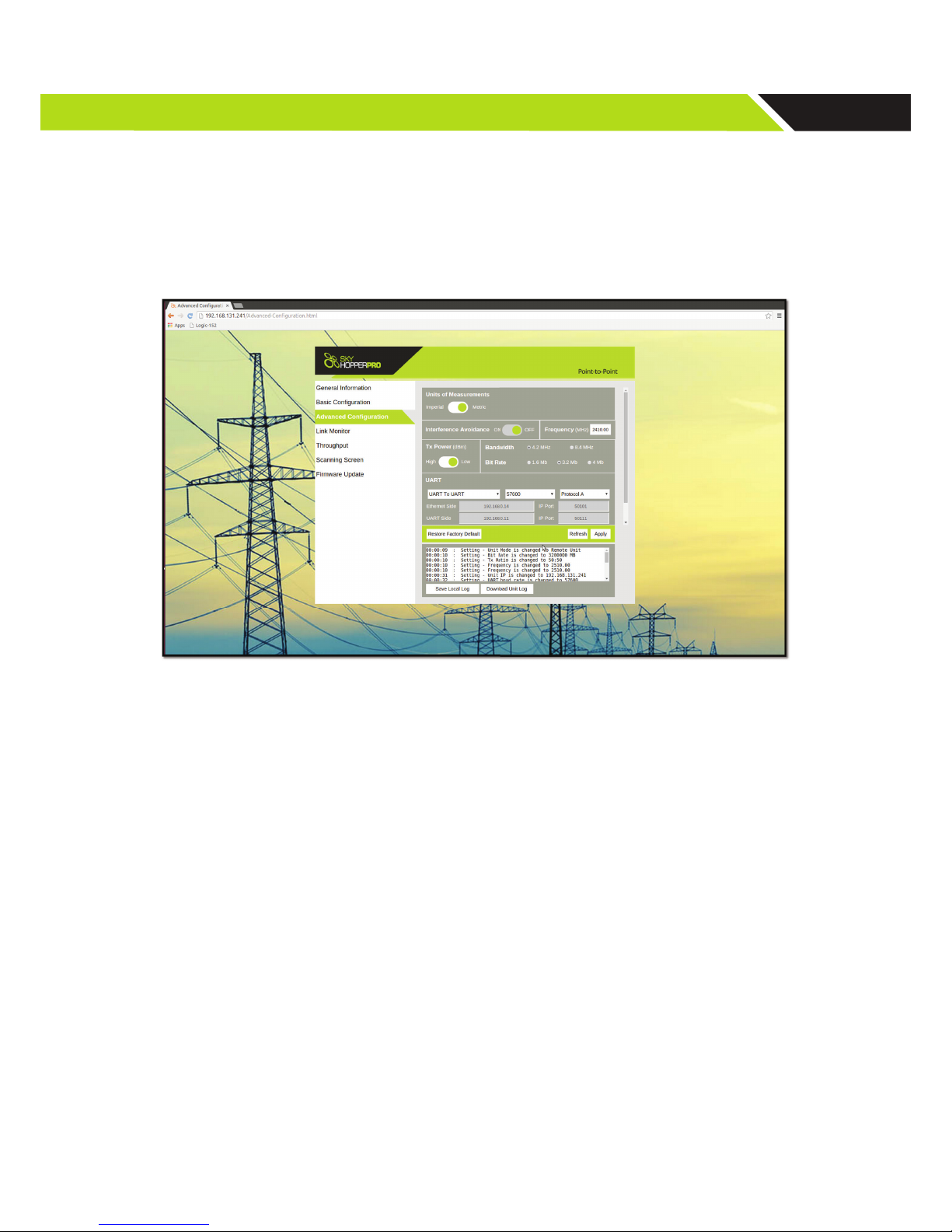
The rst stage is to setup the SkyHopper link to enable the UART interface on the link. The con guration should be setup on
both units (Remote/Aerial and Controller/Ground).
Figure 10: WebGUI advanced con guration
In the advanced con guration screen:
1. Go to the UART section
2. Enable the UART and choose UART-to-UART
3. Setup the Baud rate to 57600
4. Choose protocol C
5. Reboot the unit
6. Repeat on both Remote and Controller units
D.2. Physical Connection
After the units are con gured, the Pixhawk ight controller should be connected to the unit.
On the remote (Aerial) unit Use the Pixhawk adapter accessory which can be purchased on our website and connect it to
the serial cable provided with the SkyHopper PRO unit. Connect the adapter to the Pixhawk ight controller and the serial
cable to the unit.
On the controller (Ground) unit, connect the D-Type/9-pin accessory adapter to the serial cable supplied and connect the
cable to the unit. If the Tablet/PC has a serial port, connect it directly, if not, a USB-RS232 adapter should be used.
D.3. UART to Ethernet
There is an option to con gure the system to work with a UART-to-Ethernet con guration, which eliminates the use of the
serial cable on the Ground Unit.
Please refer to the UART-to-Ethernet Connection Guide online at www.skyhopper.biz/prosupport.
Page 20

19
Appendix E – Troubleshooting
Symptom Possible Cause Action Needed
LED is off Not connected to power source
or battery is empty
1. Verify power cable properly connected to the
SkyHopper PRO PWR connector
2. Verify that the battery or power supply is connected to the SkyHopper PRO power cable
and to a power outlet
3. Replace the battery or check the outlet.
4. Replace the power cable
LED light is always on PTP – Unit is in boot mode PTP
1. Check the power source
2. Reboot the SkyHopper PRO
Cannot connect to
SkyHopper PRO using
Web GUI
1. The PC isn’t congured with a
correct static IP
2. Unit isn’t powered up
3. Ethernet cable isn’t connected
or data cable is damaged
4. Firewall is blocking traffic
5. ETH port set to “auto negotiation off” with 1GE
6. Trying to connect to remote unit
when link is down.
1. Verify your PC is set with a static IP in the subnet of 192.168.131.xxx
2. Check that the ETH port is set to “auto negotiation on”
3. Verify the unit is powered up
4. Verify that the PC ETH port status isn’t unplugged or disabled
5. Disable the PC rewall
6. Verify ETH cable is connected to the PCs ETH
port and to the SkyHopper PRO MAIN connector
7. If needed: replace cables.
8. Ping the unit
9. Try to connect to the local unit and verify link
is up
No link between
SkyHopper PRO units
1. Conguration isn’t the same on
all of the SkyHopper PRO units
2. PTP – both units set as VC or
both as Node
3. The units aren’t within reception
range
1. Connect to each unit and verify they have the
same conguration
2. Verify 1 unit is set as a VC and the other as a
Node.
3. Verify that TX power is set to the maximum.
4. Verify the antennas t the Frequency used (antenna spec)
Data with high delay and
disconnecting data
Trying to send a higher amount
of data than the allocated band-
width sent to the unit
1. Verify that the data bandwidth sent to the unit
from the connected device(s) does not exceed
the allocated bandwidth (in its conguration)
2. Decrease the data received by the data source
or change the allocated bandwidth via the
Web GUI
Technical Suppor t Inquiries
For technical support for SkyHopper PRO, please contact:
 Loading...