

Page 1
http://www.SkyhawkRC.com
SkyhawkRC
F900 user manual
V1.0
2014-07-28
http://www.SkyhawkRC.com
Page 2

http://www.SkyhawkRC.com
1). Manual Mode
2). GPS Auto Hovering
3). GPS Auto Navigation
4). Auto Back Landing
Declaration
Thanks for using SkyhawkRC F900 aircraft. Please read manual carefully before operation, it will help you
understand the product deeply and make sure to operate it safely and correctly.
Please operate the product according to manual strictly, all product has finished outdoor tests and adjustment to
ensure user can operate it quickly and successfully while received. Meanwhile, we also provide related
equipment, excellent technical support and lifetime maintenance service are very important for your use.
The product is a remote controlled aircraft, wrong and impertinent operation will cause unintended consequences.
Please do not adjust any parameters or modify the aircraft structure or use for illegal purposes. Due to cannot
constrain user’s specific purpose, we will not bear any legal responsibility or compensation in the process of use.
If user uses this product, it indicates that you have accepted this clause.
Operation Requirements
1. The person under the age of 16, after drinking or taking drugs cannot operate this product.
2. If you are beginners, please operate it under the guidance of experienced professionals.
3. Please stay away from the crowd while operation, please operate it in a special site.
4. The product equips with 6S Li-Po battery.
5. Aircraft does not equip with waterproof, dustproof ability, please do not operate it under bad weather or the
temperature below 5 degrees.
6. Aircraft belongs to precision mechanical and electrical integration product, please do not make modification or
disassembly, otherwise, it will not work normally.
7. Please choose original accessories to make sure it can be used normally.
7. Be sure to use the product under local laws and regulations.
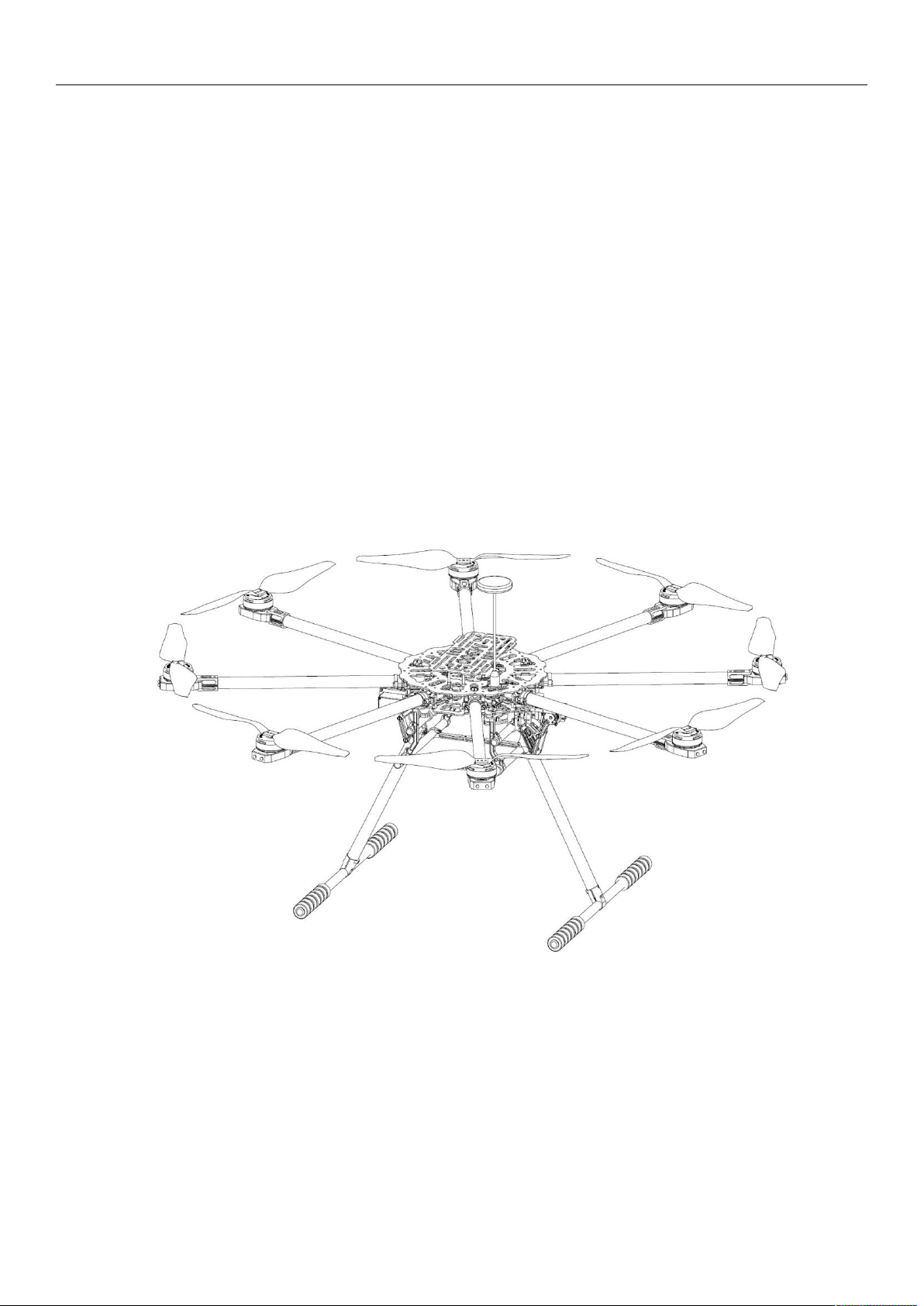
Brief Introduction
F900 is a professional aerial photography octocopter aircraft for application. Fuselage adopts folding design, easy
to carry, quick and flexible to operate, safe and stable to use, etc. It has been assembled and adjusted well in
factory, users only need simple installation and can enjoy it. Fuselage integrates battery installation board, power
distribution unit, folding arms, GPS folding bracket, flight control LED indicator and quick release landing gear
components. Motor base integrates high-speed ESC. Landing gear adopts in-built shock absorption components,
folding gear, gimbal installation gear and image transmission installation place. Modular design can realize
flexible collocation of the whole aircraft system and satisfy various of demands of application-level aerial
photography.
Working Mode:
http://www.SkyhawkRC.com
Page 3
Other Characteristic:
1). F/S (Auto back landing while losing signal), black box.
2). LED indicator
3). Fuselage direction LED indicator
4). Remote control/android mobile GCS/PC GCS
5). Android mobile/PC GCS parameters adjustment.
6). Common receiver/ S-BUS receiver
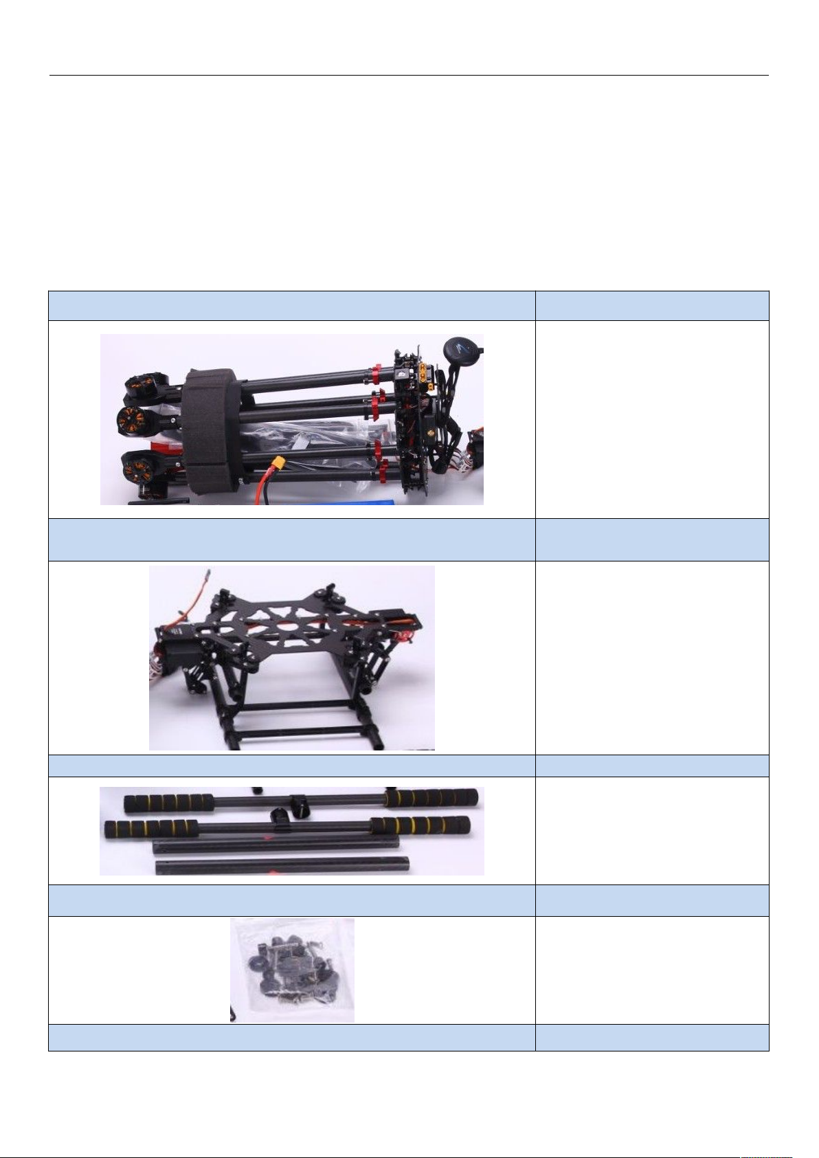
Accessories Details
http://www.SkyhawkRC.com
Fuselage 1 PC
3K carbon fiber
Titanium alloy
YS-X4 V2 standard
Landing Gear Center Frame 1PC
3K carbon fiber
Titanium alloy
Landing Gear Carbon Tube 1 UNIT
Accessories Bag 1 BAG
Screw Bag 1 BAG
http://www.SkyhawkRC.com
Quick release key
Propeller clip
screws
Page 4

http://www.SkyhawkRC.com
1). Please check if the switch and joysticks of remote control are in right position, user must turn on remote
2). Please check the structure of fuselage, propellers and working state before flight, if any questions exist, please
WIFI antenna 1 PC
2.4G WIFI antenna
Tools Bag 1 BAG
Package case 1 PC
Aluminum case
Assemble and Flight Notice
The propellers of F900 aircraft have huge damage during working, please take care of safety at all times to avoid
accident harm and loss.
Assemble Notice
1). Fuselage moving parts are marked as red and safety sign, while holding these parts, please note their moving
scope to avoid injury.
2). Please keep antenna of receiver unfold and down with no obstructions, keep antenna of image transmission
far away from receiver to avoid signal blocking or interfered and lose control.
3). Please install the propellers according to the numbers between propellers and arms.
4). Please do not tear installed screws down to avoid fuselage loose or damage.
5). Please do not change installation place and direction of fuselage, it will affect aircraft’s normal working.
6). To test electric retractable landing gear, please keep it away from ground
Flight Notice
control firstly before flight.
inquire our CSR in time.
http://www.SkyhawkRC.com
Page 5
3). Make sure battery in sufficient power before flight, otherwise, replace a new battery.
4). During flight, please keep away from the crowd, power lines, buildings, signal tower, etc.
5). Please operate under safety taking off weight, do not use much heavy battery or more batteries to achieve
long flight time purpose.
6). Please do not take off until GPS 7 satellites (red LED indicator disappears).
7). Open GCS on android mobile and connect to aircraft, real-time monitor its working state.
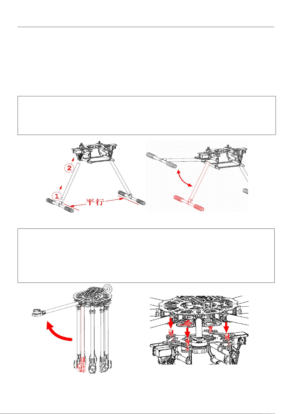
1) Please put the gear side pipe inserted into the bottom T type aluminum pipe and twist M3x16mm and
M3x22mm screws.
2) Please put the installed pipe inserted into landing gear center board and put it on ground to keep two bottom
pipes parallel and twist center board M3x8mm screws.
3)
Please check the landing gear manually, in normal, it can be retractable by hands smoothly.
1) Remove packing materials, put the center board up, unfold the arms one by one, the arms will be locked
automatically while in right location. Please pay attention to their movement scope to avoid clipping fingers.
2) F900 adopts “X” type structure, the front is two red motor base. To put fuselage on landing gear horizontally
and insert quick release key and turn 90 degree in clockwise, it will be locked automatically.
3) Unfold GPS support and twist fixed nut to make antenna no waggle, check the “▲” sign on GPS antenna
and make it point to the front, not deflective, otherwise, it will affect its performance while hovering.
4) Insert reinforced screws on center board to make arms locked better.
Landing Gear Installation
http://www.SkyhawkRC.com
Fuselage Installation
http://www.SkyhawkRC.com
Page 6

Propellers Installation
1) Please install propellers to motors according to numbers between propellers and arms. M1 and
M2 is the front.
2)
Check rotating direction of propellers, from the upper of fuselage, M1, M3, M5 and M7 rotate in
anticlockwise direction and M2, M4, M6 and M8 rotate in clockwise direction.
http://www.SkyhawkRC.com
Power Distribution Unit(PDU)
F900 fuselage integrates XT60 power distribution port can output two way power, its voltage is equal to battery
voltage. Bottom two XT60 ports are for aircraft F900.
http://www.SkyhawkRC.com
Page 7

http://www.SkyhawkRC.com
Diagonal Motor Wheelbase
Arm Length
Center Board Diameter
Max Spread Size
Fuselage Weight(motors, ESC, propellers
and flight control included)
Power port can accept two batteries connected for aircraft. (to use two batteries connected together, the voltage
of them must be same).
Gimbal Mount Size
Technical Parameters
Fuselage
920 mm
422 mm
230 mm
1260 x 1260 x 535 mm
2720 g
http://www.SkyhawkRC.com
Page 8

http://www.SkyhawkRC.com
Landing Gear Size(gear down)
Landing Gear Weight
Motor
Take Off Weight
Battery
Working Temperature
Wind Resistance
348 x 400 x 350 mm
630 g
Power
C3510 KV580
Propeller 1355 3K carbon fiber
ESC
Flight
Aircraft Weight 3.35Kg
Flight Time(no payload) 31min (6S 15000mAh LiPo take off weight 5.05Kg)
3~6S 25A, refresh rate 30~450Hz, driver frequency
8KHz/24KHz
≤7.7Kg
LiPo 6S 10000mAh~20000mAh 10~25C
5~40℃
<5.4m/s (6.5Kg take off weight)
Remote Control and LED Indicator
Unlock and start motors
For safety, flight control locks throttle signal of motors, motors will not start until unlock it.
In regards to left-hand throttle(Japanese user mode 1 and US users mode 2) layout, need to operate outside “八
“ type to unlock throttle, for right-hand throttle(Chinese user mode 3 and European users mode 4) layout, need to
operate “V” type to unlock throttle.
If there is no pushing throttle action within 5 seconds, throttle will be locked again.
Flight Mode
http://www.SkyhawkRC.com
Page 9

http://www.SkyhawkRC.com
Blue LED(manual
mode,GPS no
satellite)
Green LED(GPS
mode)
F900 aircraft has 4 flight modes, they realize switch through channel 5 and channel 6 on remote control.
Flight Mode CH5 CH6
Manual 0 X (any position)
Auto Hovering 2 0
Auto Navigation 2 1
Auto Back Landing 2 2
Note: Manual flight mode is the highest priority. User can switch to manual control mode under any other
modes.
Landing Gear up/down
F900 aircraft has electric retractable gear and realize gear up/down by channel 9 on remote control, while power
cut down, user also can put the gear up/down by hand while power cut.
No matter what position of channel 9 switch located, the gear is in down state while power is on.
Working State CH9
Gear Down 2
Gear Up 0
LED Indicator
Mode
Red LED (all modes)
http://www.SkyhawkRC.com
Page 10

http://www.SkyhawkRC.com
flash
during
flight
still on
during
flight
GPS no
satelli
te
GPS 5
satellite
s
GPS 6
satellit
es
GPS 7
satellit
es or
more
3)Auto Back Landing Mode
State
Working
Mode
●●● ●● ●
disappear
Low
battery
Severe
low
power
● ●● ● ●●
User
operate
GPS
hovering
User
operate
GPS
hovering
Note: It’s better to take off until GPS 7 satellites, flight control will record taking off point as return point
while GPS signal is more than 7 satellites.
About white LED indicator
①meaning of white LED
When the attitude error is big or GPS connection loose, white LED is on.
②solutions in different situations
a) Operate aircraft in large actions: white LED disappears while stable, at this time, user can operate it normally.
b) White LED is still on: please land aircraft as soon as possible and check if the GPS connection looses or not in
time.
About low-voltage alarm
During flight, red LED flashes quickly, it indicates that battery is in low-voltage alarm, red LED is still on, it
indicates that battery is in low-voltage emergency alarm.
About barometer initialization failure
Before operation, red LED is still on, it indicates barometer failed, please restart flight control system.
About magnetic compass calibration
To make magnetic compass calibration, if attitude error is within 5 degrees, blue LED is still on, it indicates that
user can make calibration, if attitude error is out of 5 degrees(blue LED is off), it indicates user needs to make
calibration again. After completion, while flight control will save data, purple LED is still on(2seconds on and 1
second off), the purple LED will disappear while it finishes saving data.
Functions Introduction
1)Manual Mode
Under manual mode, user needs to control aircraft’s flight height by remote control and manually operate
forward/backward, left/right, up/down, turn left/right actions. Flight height is controlled by throttle joystick directly.
2)GPS Hovering Mode
While GPS hovering mode starts(GPS 7 satellites or more, red LED disappears), adjust throttle and rudder
joysticks to middle position, it will lock the current flight height and position. Meanwhile, user can also adjust the
position of aircraft by two joysticks, it will be locked on new flight height and position after loosing joysticks.
Unlock motors and GPS positioning successfully(GPS 7 satellites or more, red LED disappears), aircraft will
record return point automatically.
http://www.SkyhawkRC.com
Page 11

http://www.SkyhawkRC.com
1. Install CCS software on android mobile or tablet(we will send GCS software to user after purchase done)
GPS mode, CH6 switch to “2” , flight control will control aircraft return home and land. During return, it is not
controlled by remote control, while it returns to the height of landing point, it will land slowly, at this time, user
can adjust its landing point by remote control in order to find a more suitable landing point and throttle
controlled by flight control during landing.
Preparations Before Flight
2. Check remote control functions and android ground station data
1). Turn on remote control, CH5 and CH6 switch to “0” position, CH9 switches to “2” position, cut down ESC
power and connect flight control power, open Android mobile or tablet WIFI, search aircraft name “M900-XXX”,
password “54321”, start GCS software, switch to “Data” interface and check “Flight Mode” bar, check if the flight
modes are the same with remote control(according to the form between CH5 and CH6).
Flight Mode CH5 CH6
Manual 0 X (any position)
Auto Hovering 2 0
Auto Navigation 2 1
Auto Back Landing 2 2
http://www.SkyhawkRC.com
Page 12

http://www.SkyhawkRC.com
2). Check failure safety(F/S): hold aircraft away from ground, switch CH5 CH6 to manual mode, switch CH9 to “0”
position, turn off remote control, “Flight Mode” display “Back Landing” on GCS software and gear down, it
indicates the setting of failure safety(F/S) is right, user can put aircraft down and turn on remote control and check
other settings later.
3. Motors start guidance: pull throttle joystick to the bottom, switch CH5, CH6 to “0” position, (mode 2 left-hand
throttle as sample), pull left joystick to bottom left corner, right joystick to bottom right corner as “八” type and keep
the action about 3-5 seconds, loose two joysticks, push left throttle joystick slightly to start motors, push throttle
higher slowly and check if motors are controlled normally, while left throttle joystick pulls to bottom again, motors
will stop running.
Notice:
(1) Both manual and auto hovering mode can start motors in this way.
(2) Under auto hovering mode, user needs to push throttle joystick to at least half position before taking off. There
is no limit under manual mode.
(3) Execute the operation, if there is no operation of pushing throttle joystick in 5 seconds, the motors will stop
running and be locked automatically. User needs to execute the operation one more before taking off.
(4) Under manual mode, if throttle joystick is not in bottom position, motors will not stop running.
(5) Under auto hovering mode, if flight height lands to minimum and flight control detects no flight height change,
motors will stop running and be locked automatically.
(6) Under auto navigation and auto back landing mode, all the operations will be completely controlled by flight
control.
(7) Under strong wind flight environment, atmospheric wave is volatile heavily. There is a possibility that motors
cannot stop running under auto hovering and auto back landing mode, in this situation, user only need to pull
throttle joystick to bottom position and switch to manual mode, motors will stop running later.
Magnetic Compass Calibration
F900 aircraft has made magnetic compass calibration before delivery, in general, it is unnecessary to make
calibration again.
http://www.SkyhawkRC.com
Page 13

http://www.SkyhawkRC.com
(1) Please make calibration outdoor, do not operate it inside building, nearby vehicle environment or magnetic
environment.
(2) Other occasions for re-calibration: the position of electric components has moved or auto hovering
performance is not good.
There are 3 steps to make calibration: make horizontal calibration firstly and later vertical calibration and finally
save compass data. There are related tips under “Settings” bar for every step on GCS software.
Details as below:
Step 1: disconnect ESC power, connect flight control power, switch to manual mode and pull throttle to bottom.
Step 2: click “Magnetic Compass” button in “Settings” interface.
Step 3: click “Horizontal Alignment” and “OK” button, if user does not want to continue, can click “cancel”.
Step 4: keep aircraft horizontal(hold by hands), make sure the blue LED is still on, and rotate aircraft 5-6 circles,
keep blue LED on while rotation, if the blue LED is off, please stop and adjust aircraft well and continue.
Step 5: click “Vertical Alignment” and “OK” button, if user does not want to continue, can click “cancel”
Step 6: keep aircraft vertical(hold by hands), make sure the blue LED on, and rotate aircraft 5-6 circles, keep blue
LED on while rotation, if the blue LED is off, please stop and adjust aircraft well and continue.
Step 7: click “Save Alignment” and “OK” button.
http://www.SkyhawkRC.com
Page 14

http://www.SkyhawkRC.com
1). click “ Map” and “Tool” button
2). click “Add Waypoints” and “OK” button.
3). set waypoints on map and it will form air line automatically.
Step 8: ground station will switch to “Control” interface automatically, at this time, flight control will save magnetic
compass data, during the process, purple LED is on(2seconds flash and 1 second off), wait a few seconds until
purple light goes out and will display 1 blue circle and 1 red circle, the calibration is completed.
excellent qualified unqualified
As photos above, if red and blue circles are almost in coincident, it indicates calibration is successful. If not,
please execute the operation again.
Note: if the flight control components are installed well and no disassembly, it is unnecessary to make calibration
again.
Auto Navigation
Step 1: Air line Setting
http://www.SkyhawkRC.com
Page 15

4). click “Tool” and “Default Tool” button.
Step 2: upload and verify waypoints
1). click “Tool”, “Upload Waypoints” and “OK” buttons.
2). check if all waypoints change from orange to blue and confirm if they are uploaded successfully(it indicates
3). click “Tool”, “Verify Waypoints” and “OK” buttons.
4). check if all waypoints are blue color and confirm if they are verified successfully(it indicates that all waypoints
5). Switch remote control CH5 to “2” and CH6 to “1” position to start auto navigation
6). Click “SPC” and “Enable Skyway” and “OK” buttons, the aircraft will fly to the first pointed waypoint and
http://www.SkyhawkRC.com
that all waypoints are uploaded successfully while changing to blue color, if not, please re-upload waypoints until
all of them change to blue color).
are verified successfully while they are all blue color, if not, please re-upload and re-verify waypoints until all of
them change to blue color).
.
hovering, click “SPC”, change number “1” to “2” on the first line, aircraft will fly according to the setting
http://www.SkyhawkRC.com
Page 16

http://www.SkyhawkRC.com
7). To cancel auto navigation, user can switch CH5 of remote control to “0” (manual mode) or switch CH6 to “0”
waypoints(2,3,4,...) until finish all waypoints and fly back to the first setting waypoint and hovering.
(auto hovering mode).
Note: If not upload waypoints correctly, switch to auto navigation, aircraft will fly away.
If you have any questions about our products or service,please feel free contact us by
following:
Homepage:http://www.SkyhawkRC.com
Mail:SkyhawkRC@gmail.com
Skype:SkyhawkRC1
Follow us:
https://twitter.com/SkyhawkRC
https://www.facebook.com/skyhawkRC
https://plus.google.com/+SkyhawkrcOctocopter
https://www.youtube.com/channel/UCmMBuprnOUiYiVQ4xTDBjGw
http://www.SkyhawkRC.com
 Loading...