

Page 1

Flight Control System
User’s Guide
www.sky-drones.com
All rights reserved
Page 2

2
6
6
6
6
7
7
8
8
8
8
9
9
9
10
10
10
11
11
11
11
11
12
13
13
13
13
13
13
14
14
14
14
14
15
15
15
15
15
17
17
17
17
CONTENT
CONTENT
Introduction
Hardware
SmartAP PRO
SmartAP MAX
SmartAP GNSS
SmartAP RTK
SmartAP PDB
Software
Supported airframes
About
SmartAP PRO
Introduction
Set includes
Description
Capabilities
General
Sensors
Flight Modes
Size and Weight
Previous versions
SmartAP PRO 2
SmartAP PRO 1
SmartAP MAX
Introduction
Set includes
Description
Flight performance
General
Processor
Sensors
Flight Modes
Interfaces
Size and Weight
SmartAP GNSS
Specifications
Features
Package includes
Dimensions
SmartAP RTK
Specifications
Features
Package includes
SmartAP AutoPilot User’s Guide CONTENT
Sky-Drones - SmartAP Flight Control Systems 2 / 89
Page 3

18
18
18
19
19
19
19
19
20
20
20
21
21
22
22
22
22
22
22
23
23
24
25
27
27
27
27
27
27
28
28
29
29
29
30
30
30
31
32
32
33
34
34
35
36
SmartAP PDB
Introduction
Features
SmartAP PRO
Mounting the board
Connections
External GNSS / MAG
SmartAP PRO 0.2 and later
SmartAP PRO 0.1 and earlier
GPS Receiver
RC Receiver
RSSI Monitoring
Motors ESC
Telemetry module
OSD Video
Electromagnetic sounder
Power supply
LED & Buzzer
Pressure sensor foam
Dimensions
SmartAP PRO v .2 pinout
SmartAP PRO v .1 pinout
SmartAP PRO v .0 pinout
SmartAP MAX
Mounting the System
Autopilot
GNSS / MAG
Connecting Peripherals
Metal case version
Plastic case version
RC Receiver
ESC / Motors PWM
GNSS / MAG
Telemetry Module
Power Module
Electromagnetic sounder
Camera trigger
Assembled System
SmartAP PDB
Pinout
Soldering
Powering the autopilot
SmartAP PRO
SmartAP MAX
Buzzer support
SmartAP AutoPilot User’s Guide CONTENT
Sky-Drones - SmartAP Flight Control Systems 3 / 89
Page 4

36
37
42
42
43
43
44
44
45
45
47
49
49
51
51
51
52
52
52
53
54
54
55
55
56
56
57
58
58
60
61
62
62
62
63
64
65
65
65
66
68
68
68
68
68
Voltage and current sensors
Drivers installation
Getting the software
First run
Create account
World pane
App Menu
UAV Settings
Links Management
First connection
Firmware update
Custom firmware upload
Getting the log
General configuration
General
Airframe
System orientation
Landing Gear
Motors IDLE speed
Radio
Sensors
Accelerometer calibration
Gyroscope calibration
Magnetometer
GNSS Configuration
Battery
Tuning
Control
OSD
Camera
Parameters
Standard PID presets
MicroDrones MD4-1000 Quadcopter
T960 Hexacopter
F450 Quadcopter
3DR Hexacopter
Updating GNSS Module
Getting U-Center
RTK GNSS Configuration update
SmartAP PRO Onboard GNSS module update
Modes overview
Flight Modes overview
Mode Switch: 3 position switch (Main mode control):
Auto Switch: 2 position switch (Auto mode control):
RTH Switch: 2 position switch (RTH mode control):
SmartAP AutoPilot User’s Guide CONTENT
Sky-Drones - SmartAP Flight Control Systems 4 / 89
Page 5

68
68
68
69
69
69
69
70
70
71
71
71
72
72
78
80
80
80
81
81
82
83
86
87
87
87
87
87
87
89
Before take off
The Flight
After landing
Transmitter commands
ARM
DISARM
Accelerometer calibration
Gyroscope calibration
Magnetometer calibration
Flying with SmartAP GCS
World Pane overview
Getting the video feed
Autonomous Flights
Waypoints flight
Guided flight
Flying with RTK GNSS
Locating the antenna
Connecting in SmartAP GCS
Starting Survey-In
Survey-In completed
RTK Modes
Geotag images
Processing the Logs
Support
Safety
Safety basics
Additional safety information
Support
Disclaimer
Revision history
SmartAP AutoPilot User’s Guide CONTENT
Sky-Drones - SmartAP Flight Control Systems 5 / 89
Page 6
Introduction
Sky-Drones - the leading manufacturer of autopilots and flight control systems solutions which can be applied to a wide range of Drones (UAVs)
applications such as Surveying, Mapping, Inspection, Security, Safety and High-Quality Media production. The company has an outstanding
background and experience in Research and Development, Manufacturing and Delivering products and solutions for extremely rapidly growing
market in Drones / UAV segment.
Sky-Drones Docs - online documentation whic will help introducing the most basic ideas of assembling, configuring and flying a drone with
SmartAP Autopilot developed by Sky-Drones. This page gives an overview about the available flight controller hardware and software.
Hardware
At the moment, active and available versions of the hardware are SmartAP PRO and SmartAP MAX
SmartAP PRO
Industry leading Flight Control System with outstanding reliability, positioning precision and control accuracy for professional applications with
various peripherals already integrated onboard
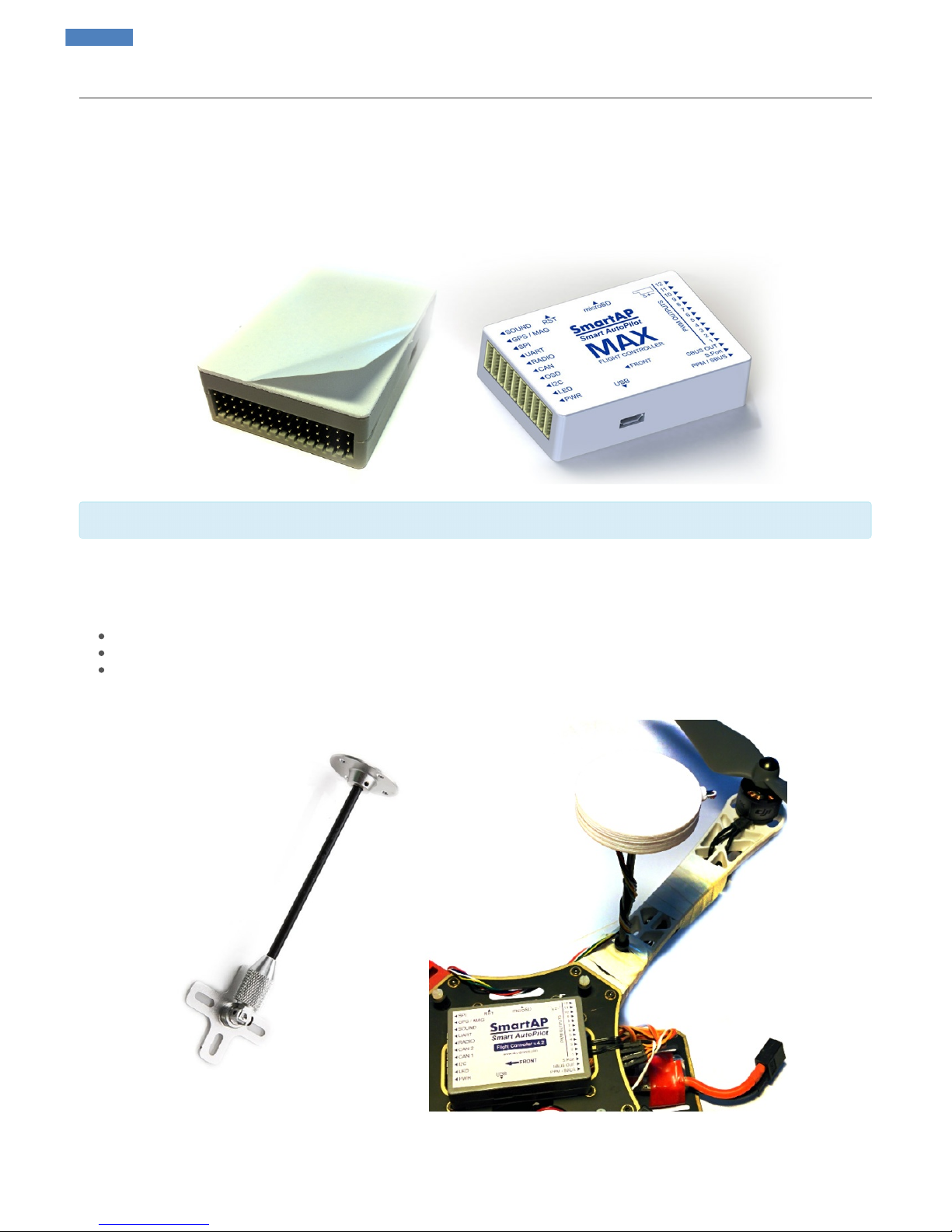
SmartAP MAX
SmartAP AutoPilot User’s Guide Introduction
Sky-Drones - SmartAP Flight Control Systems 6 / 89
Page 7
As well as many other peripherals and electronics needed for autonomous unmanned aerial vehicles:
Flight Control System aimed at the wide range of purposes for consumer and professional applications with the compact main core and externally
connected peripherals
SmartAP GNSS
GPS/GLONASS receiver with integrated patch antenna, magnetometer and pressure sensor
SmartAP RTK
GPS/GLONASS RTK (Real-Time Kinematics) receiver for high-precision positioning
SmartAP AutoPilot User’s Guide Introduction
Sky-Drones - SmartAP Flight Control Systems 7 / 89
Page 8
Purchase the Hardware in official Sky-Drones Store
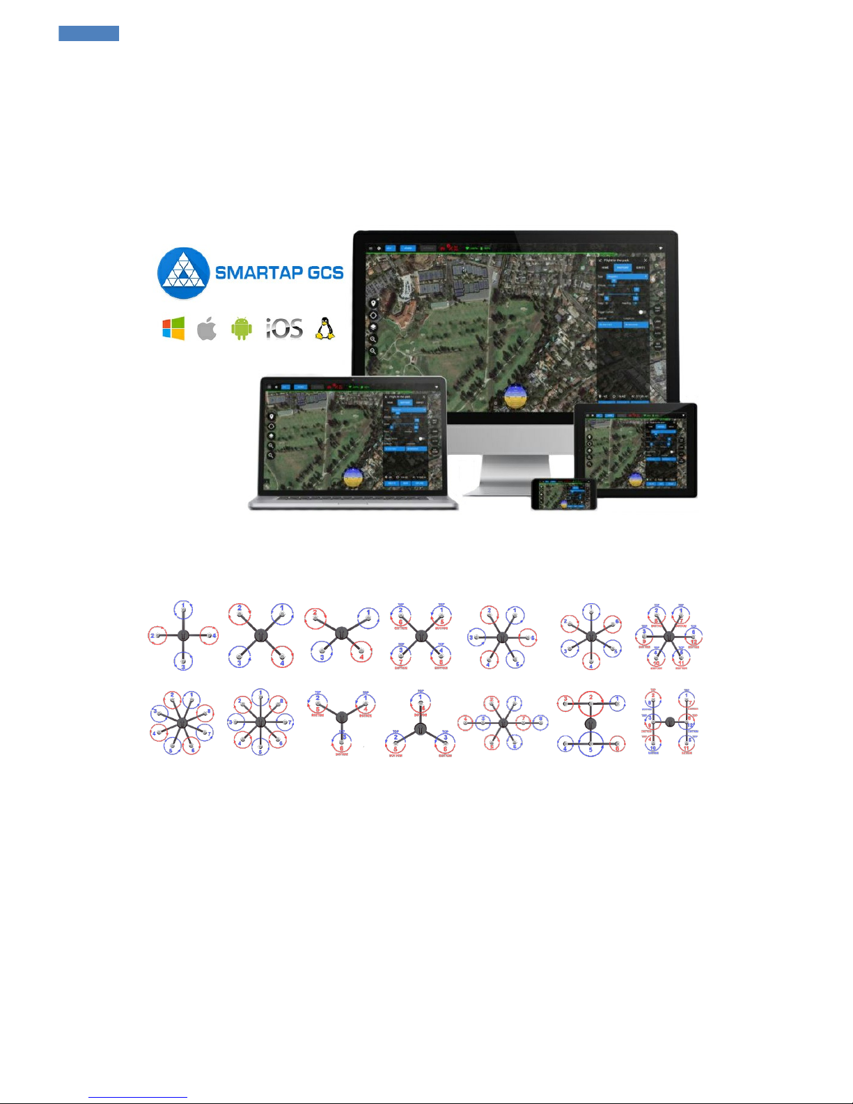
Software
SmartAP GCS (Ground Control Station) is the software application which allows you to plan and create autonomous missions for your SmartAP
Autopilot as well as control the UAV using intuitive high-level commands. SmartAP GCS also includes Configurator.
Download the Software and more
Supported airframes
Can't find yours? Let us know!
About
All further information can be asked using the Contact Form.
SmartAP PDB
Power Distribution Board for ESCs / Motors power supply and 5V / 12V generation
SmartAP AutoPilot User’s Guide Introduction
Sky-Drones - SmartAP Flight Control Systems 8 / 89
Page 9
SmartAP PRO
Introduction
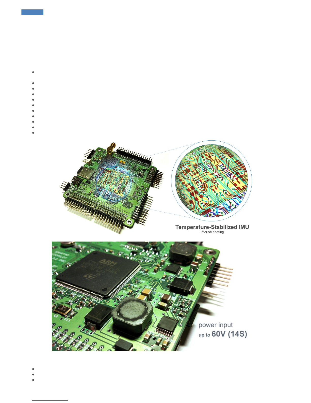
SmartAP PRO Autopilot is the latest generation of professional flight control system for multirotor Unmanned Aerial Vehicles capable of fully
autonomous flight. It has a powerful microcontroller, multiple redundant 9-axis Inertial Measurement Unit (Gyroscopes, Accelerometers,
Magnetometer) with temperature stabilization, integrated telemetry module, external GNSS module with the latest with integrated magnetometer.
SmartAP supports any type of multirotor UAV with outstanding navigation and control precision.
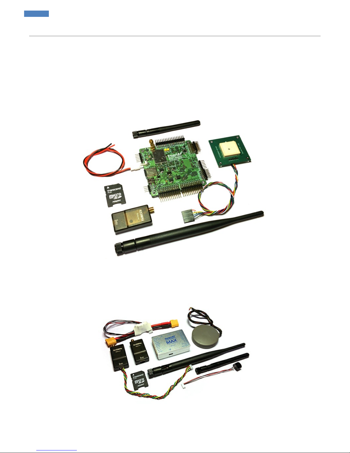
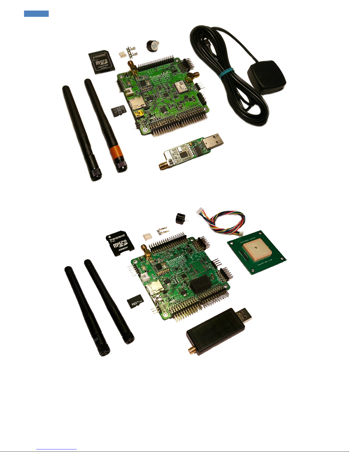
Set includes
1. SmartAP PRO Flight Controller Main board
2. External GNSS / Magnetometer module
3. Ground telemetry module
SmartAP AutoPilot User’s Guide SmartAP PRO
Sky-Drones - SmartAP Flight Control Systems 9 / 89
Page 10
4. Onboard telemetry antenna
5. High-gain ground telemetry antenna
6. Power input cable
7. MicroSD card with SD card adapter
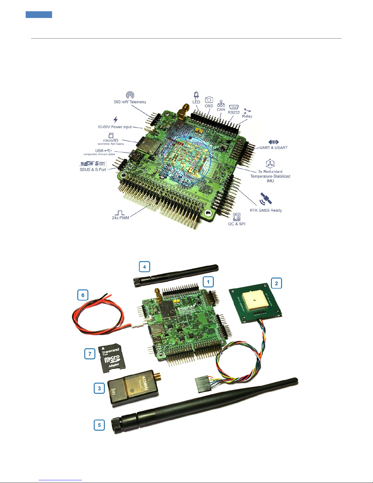
Description
Capabilities
Outstanding flight stability in all modes - manual (user control), position hold (semi-autonomous control) and auto (fully autonomous
navigation and control)
Temperature-stabilized IMU
Fully compatible with SmartAP GCS Ground Control Station for Configuration and Mission Planning
Integrated OSD (On-Screen Display for FPV)
Accurate GPS Position hold (up to 40cm with good GNSS reception quality)
Accurate Altitude hold (up to 10 cm), manual altitude override
Return to Home flight mode
Fully autonomous waypoints flight mode
Guided flight mode
Various failsafe events configuration and triggering
Operating temperature -40...+85C
General
Powerful microcontroller 32 bit 168 MHz STM32F4 ARM Cortex M4
Compact board size of 8x8 cm (3.15"x3.15"), weight 60g, 6 layers PCB design
Power supply from the main LiPO battery (3S - 14S) support, up to 60 Volts
SmartAP AutoPilot User’s Guide SmartAP PRO
Sky-Drones - SmartAP Flight Control Systems 10 / 89
Page 11

Power supply from BEC 5V support
12V, 5V, 3.3V generated onboard
Integrated GNSS receiver UBlox NEO M8N, GPS/GLONASS, up to 24 sats, 10 Hz), active antenna
Exnternal GNSS module support (primary configuration)
Integrated 500 mW telemetry module (primary configuration)
External telemetry module support
Integrated OSD module
Up to 24 PWM I/O support (5V out, high-power)
SBUS input support
FrSky S.Port output support
USB interface for configuration / firmware update
Various communication lines (UART/USART, RS232, I2C, SPI)
6-pin JTAG port for programming / debugging
MicroSD card driven by 4-bit SDIO interface for data-logging / parameters
Backup battery for real-time clock and GNSS receiver
Integrated main LiPo battery voltage monitoring
4 ADC inputs, battery voltage / current monitoring
Electromagnetic sounder
3-channels bright LED support (up to 300mA/ch)
RGB LED support
2-channel solid state relay
Sensors
IMU: InvenSense MPU-9150
Magnetometer: Honeywell HMC5983L
Pressure sensors: MS5611
Flight Modes
Stabilization
Altitude Hold
Position Hold
Return to Home
Autonomous Waypoints Flight
Guided
Follow me
Take off
Landing
Size and Weight
Length: 80mm
Width: 80mm
Height: 17mm
Weight: 39g
Previous versions
SmartAP PRO 2
SmartAP AutoPilot User’s Guide SmartAP PRO
Sky-Drones - SmartAP Flight Control Systems 11 / 89
Page 12
SmartAP PRO 1
SmartAP AutoPilot User’s Guide SmartAP PRO
Sky-Drones - SmartAP Flight Control Systems 12 / 89
Page 13
SmartAP MAX
Introduction
SmartAP MAX Autopilot is the latest generation flight control system for multirotor Unmanned Aerial Vehicles of various configurations and sizes
aimed at the wide range of applications. The main feature of the system is the capability of fully autonomous flight including take off, waypoints
flight, landing and much more. The core is based on powerful 32-bit microcontroller ST Microelectronics® STM32F4 and 9-axis Inertial
Measurement Unit. The latest UBlox® GPS module with integrated 3-axis magnetometer and pressure sensor can be connected externally for
autonomous flight capabilities as well as wireless telemetry module for system configuration, mission planning & control and in-flight monitoring
via specially designed SmartAP Ground Control Station and Configuration Tool. SmartAP MAX supports any type of multirotor UAV with
outstanding flight performance, reliability, navigation and control precision. Compact size and weight makes integration of the system fast and
easy, various I/O interfaces allow creating the applications for interaction with 3rd party electronics and payload.
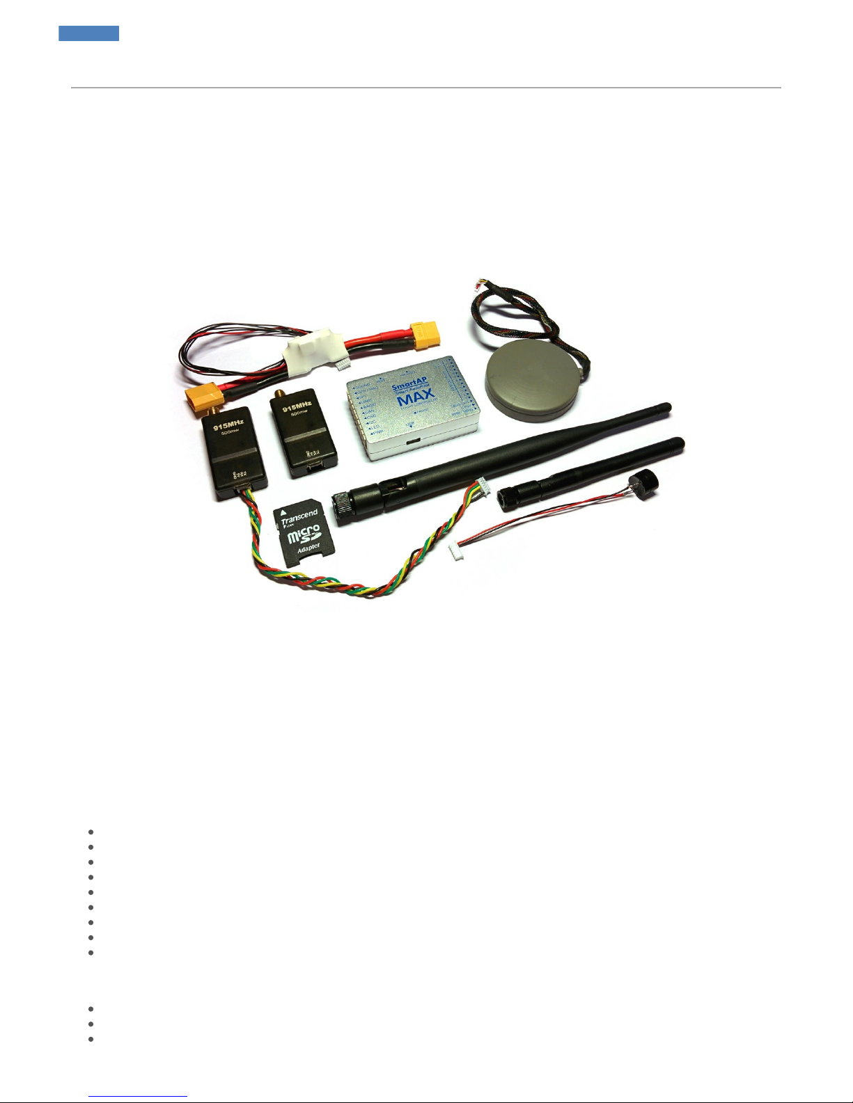
Set includes
1. SmartAP MAX Flight Controller
2. GPS / GLONASS satellite navigation module with integrated 3-axis magnetometer
3. Telemetry kit (air and ground module with antennas and connection cable)
4. DC-DC Power module and current / voltage sensor
5. MicroSD card with adapter
6. Electromagnetic sounder
Description
Flight performance
Extremely stable flight in stabilize (user control), position hold (semi-autonomous control) and autonomous (navigation and control) modes
Vibration dampened multiple redundant temperature stabilized IMU
Aluminum case for EMI protection
Native support of SmartAP Ground Control Station and Configuration Tool
Accurate GPS Position hold (up to 40cm), Accurate Altitude hold (up to 10 cm), manual
Fully autonomous waypoints flight
Return to home mode
Failsafe detection and event triggering
And many more…
General
Powerful microcontroller 32 bit 168 MHz STM32F4 ARM Cortex M4
Compatible with GPS/GLONASS receiver (UBlox NEO8, GPS/GLONASS, up to 24 sats, 10 Hz) active antenna
Integrate OSD (On-Screen Display)
SmartAP AutoPilot User’s Guide SmartAP MAX
Sky-Drones - SmartAP Flight Control Systems 13 / 89
Page 14

Up to 12 PWM I/O support (5V out)
USB interface for configuration / firmware update
Various communication lines (UART, I2C, SPI)
MicroSD, 4-bit SDIO interface for data-logging / parameters storage
Backup battery for RTC
2x ADC inputs for battery voltage / current monitoring
Electromagnetic sound audio indicator
3-channels LED support (up to 500mA / ch)
2-channels solid state relay
Processor
ST Microelectronics STM32F427VI
32 bit 168 MHz ARM Cortex M4
Hardware FPU
2 MB Flash
192 kB RAM
Sensors
Vibration dampened multiple redundant temperature stabilized IMU
2x 9-axis IMU InvenSense MPU-9250 (accelerometer, gyroscope, magnetometer)
2x Pressure sensor MS5611 (integrated and external)
1x 3-axis magnetometer HMC5883 (external)
1x UBlox M8N GPS Module (external)
Flight Modes
Stabilization
Altitude Hold
GPS Position Hold
Loiter
Return to Home
Autonomous Waypoints Flight
Guided / Follow me
Take off
Landing
Interfaces
12x PWM I/O
1x PPM / SBUS Input
1x SBUS Output
1x Power Input port
1x LED Output port
3x UART
2x I2C
1x SPI
2x CAN
1x Camera input
1x Camera output
1x USB Mini-B
Size and Weight
Length: 63mm
Width: 43mm
Height: 16mm
Weight: 21g
SmartAP AutoPilot User’s Guide SmartAP MAX
Sky-Drones - SmartAP Flight Control Systems 14 / 89
Page 15
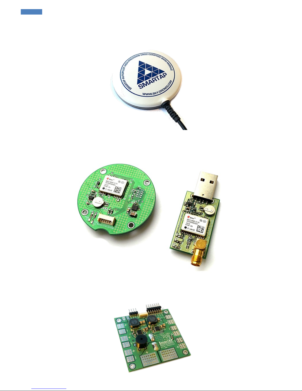
SmartAP GNSS
Specifications
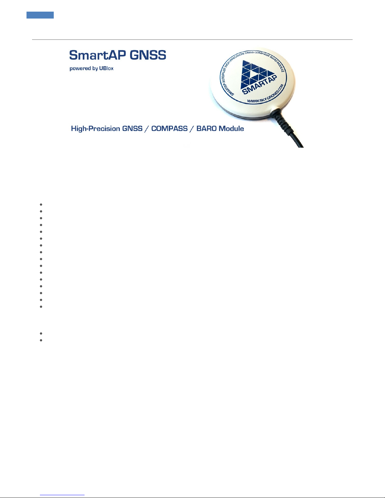
SmartAP GNSS is a compact GPS/GLONASS module with integrated active antenna, UBlox Neo-M8N chipset and 3-axis magnetometer
(compass). Fully compatible with SmartAP Autopilots.
Features
UBlox NEO M8N chipset based
Integrated SAW and LNA
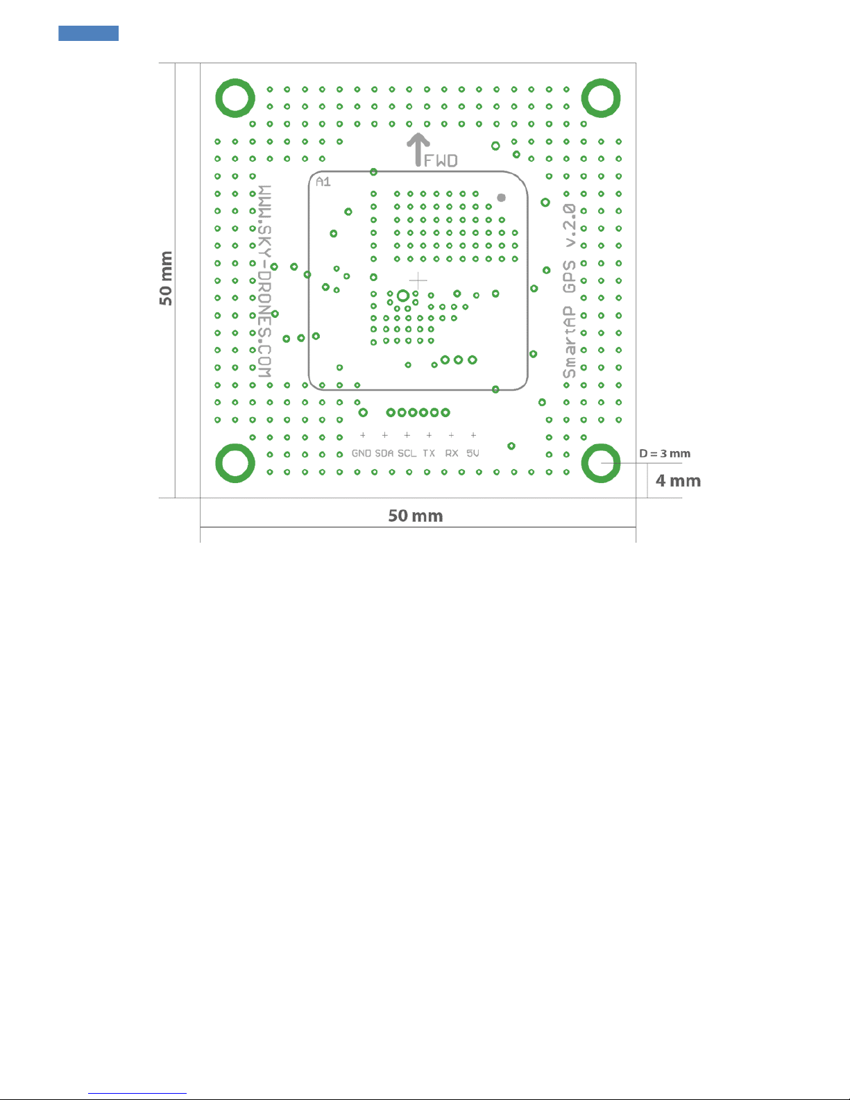
25mm ceramic patch antenna
GPS / GLONASS support
Up to 24 satellites
18 / 10 Hz update rate (GPS / GPS + GLONASS)
Rechargeable 3V lithium backup battery
Ultra-Low noise 3.3V regulator
Power and fix indicator LEDs
Exposed RX, TX, 5V and GND pads
Integrated magnetometer - HMC5883L
Footprint for pressure sensor - MS5611-01BA03
UART port for GPS interface
Diameter 75 mm
Weight 18g
Fully compatible with SmartAP Autopilots
Package includes
GNSS Module
Connection cable
Dimensions
SmartAP AutoPilot User’s Guide SmartAP GNSS
Sky-Drones - SmartAP Flight Control Systems 15 / 89
Page 16
SmartAP AutoPilot User’s Guide SmartAP GNSS
Sky-Drones - SmartAP Flight Control Systems 16 / 89
Page 17
SmartAP RTK
Specifications
This GNSS (GPS + GLONASS) module is base on RTK technology and was specially developed for SmartAP Autopilot and is intended to be
used in applications where precise positioning really matters. It's based on the latest and most precise UBlox Neo M8P chipset which provides
outstanding positioning accuracy. The set includes base station module with external active patch antenna, airborne module with integrated
patch antenna and set of cables.
Real Time Kinematic (RTK) satellite navigation is a technique used to enhance the precision of position data derived from satellite-based
positioning systems (global navigation satellite systems, GNSS). It uses measurements of the phase of the signal's carrier wave, rather than
the information content of the signal, and relies on a single reference station or interpolated virtual station to provide real-time corrections,
providing up to centimetre-level accuracy.
Features
Centimeter‑level GNSS positioning
Integrated Real Time Kinematics (RTK)
Smallest, lightest, and energy‑efficient RTK module
Complete and versatile solution due to base and rover variants
World‑leading GNSS positioning technology
UBlox NEO M8P chipset based
25mm ceramic patch antenna
GPS / GLONASS support
Up to 24 satellites
18 / 10 Hz update rate (GPS / GPS + GLONASS)
Rechargeable 3V lithium backup battery
Ultra-Low noise 3.3V regulator
Power and fix indicator LEDs
Exposed RX, TX, 5V and GND pads
Integrated magnetometer on airborne module - HMC5883L
UART port for GPS interface
USB for base station module
Airborne module cable length 30 cm
Base station module length 3 m
Fully compatible with SmartAP Autopilots
Package includes
Base station module
Active patch antenna for base station module
Airborne module with integrated patch antenna
Connection cable
SmartAP AutoPilot User’s Guide SmartAP RTK
Sky-Drones - SmartAP Flight Control Systems 17 / 89
Page 18
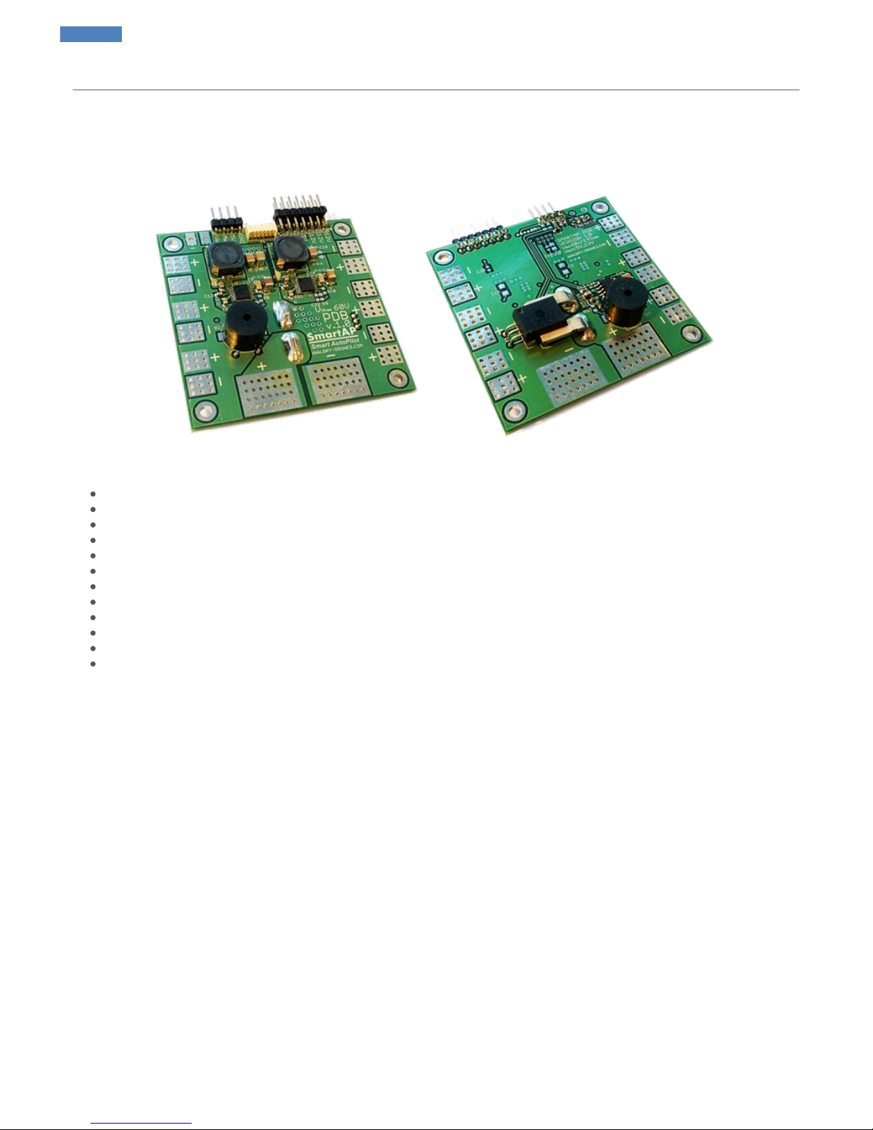
SmartAP PDB
Introduction
SmartAP PDB (Power Distribution Board) is a special board which allows transferring the power from the battery to ESCs / Motors and generate
power supply for the flight controller and other peripherals with different voltage levels. Also, PDB provides the functionality for battery voltage /
current measurements. SmartAP PDB makes high-power lines connections easier and much more reliable.
Features
Size: 65x65 mm, four 3mm mounting holes
Input voltage up to 60 Volts (14S)
Capability to handle extremenly high currents (peak current up to 400A)
Power input from the main battery, possibility to connect up to 4 independent batteries
12 pairs of pads (6 on top, 6 on bottom) for powering up to 12 motors (all possible airframe configurations supported)
Integrated voltage and current sensors
Integrated DC-DC converter from 10-60 V input (up to 14S battery) to 5V output to power peripherals
Integrated DC-DC converter from 10-60 V input (up to 14S battery) to 12V output to power peripherals
5V and 12V power output terminals (standard 2.54mm/0.1" connectors)
Integrated loud electromagnetic sounder (buzzer)
Power output for the flight controller (both 5V and battery VIN)
Fully compatible with all SmartAP Autopilots
For further information, please, refer to the Installation section.
SmartAP AutoPilot User’s Guide SmartAP PDB
Sky-Drones - SmartAP Flight Control Systems 18 / 89
Page 19
SmartAP PRO
WARNING!
1. Do not power on the board without gps and wireless telemetry modules’ antennas connected!
2. Do not disconnect antennas when the board is powered on!
Mounting the board
Mount your board on your copter airframe. It's highly recommended to mount the board as close to the geometrical center of the copter as
possible. Mounting should be done with four 3 mm nylon screws. Add rubber spacers to reduce motors’ vibration noise.
Note the "FWD" arrow to install the board properly (`FWD` = Forward).
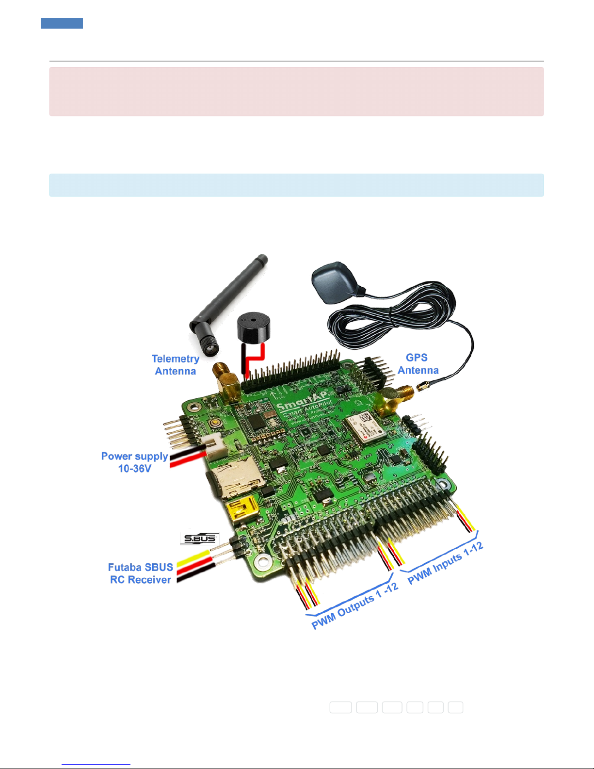
Connections
Connect the general peripherals as shown on the diagram below:
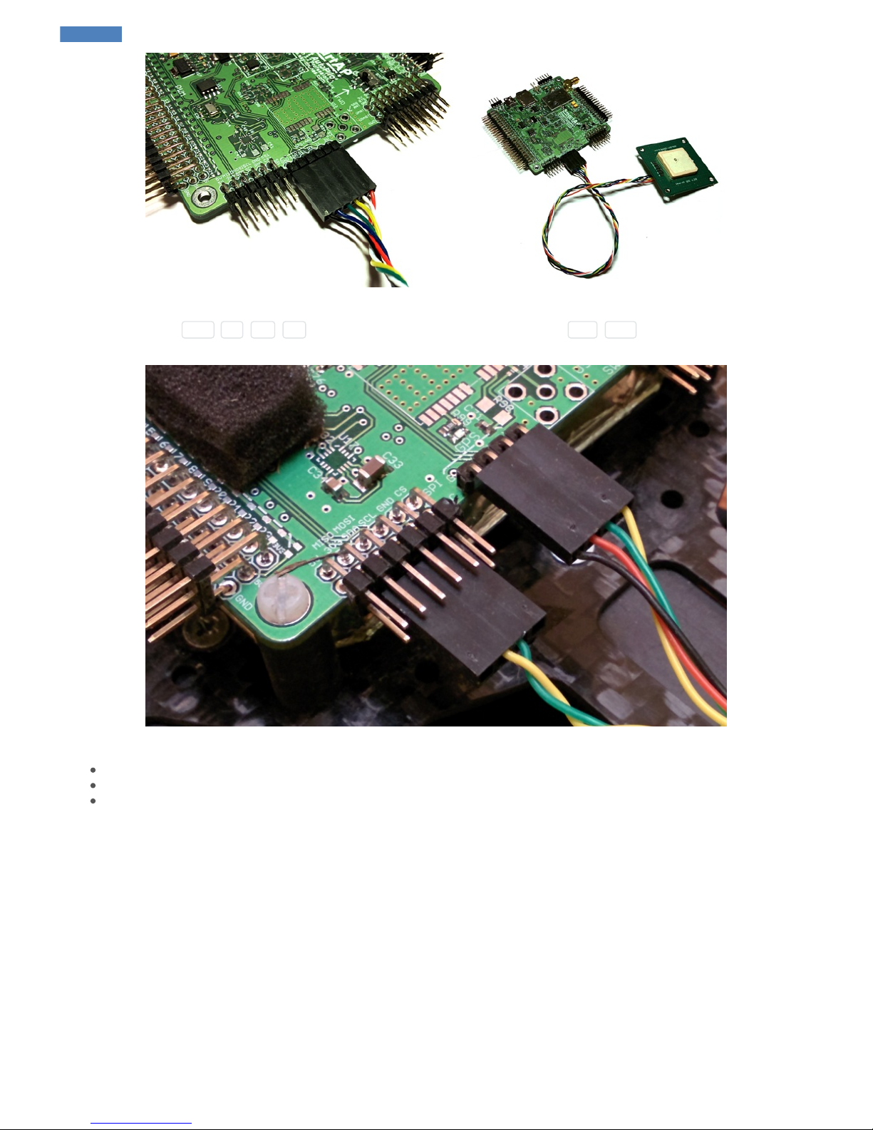
External GNSS / MAG
If you’re using external GNSS / Magnetometer module board then the connection should be as following:
SmartAP PRO 0.2 and later
GNSS / Magnetometer cable goes to dedicated GNSS / MAG port having 6 wires ( GND , SDA , SCL , RX , TX , 5V ).
SmartAP AutoPilot User’s Guide SmartAP PRO
Sky-Drones - SmartAP Flight Control Systems 19 / 89
Page 20
SmartAP PRO 0.1 and earlier
GPS Cable (4 wires: GND , 5V , RX , TX ) goes to GPS port and magnetometer cable (I2C: SCL , SDA ) goes to Magnetometer port as
shown on the picture above.
Make sure to place GPS module as far as possible from:
Main body of the airframe
RF emitting devices such as transmitters
High-current cables (ESC / motors power supply)
GPS Receiver
Connect GPS antenna to GPS antenna port. This is only for the versions which have integrated GNSS module.
RC Receiver
After mounting the board you need to connect cables from RC Receiver to SmartAP PPM / SBUS Input.
SmartAP AutoPilot User’s Guide SmartAP PRO
Sky-Drones - SmartAP Flight Control Systems 20 / 89
Page 21

You can also connect FrSky S.Port from FrSky receiver and get real-time telemetry on your FrSky transmitter (e.g. Taranis) screen. Simply
connect S.Port wire from receiver to Tel pin next to SBus input.
Channels assignments should normally be as following:
Input channel 1 – Roll
Input channel 2 – Pitch
Input channel 3 – Throttle
Input channel 4 – Yaw
Input channel 5 – Mode selection
Input channel 6 – RTH Mode
Input channel 7 – Auto Mode
Modes can be remapped in Configurator software later.
RSSI Monitoring
If you want the flight controller to read the information about RSSI (Received Signal Strength Indicator) from RC receiver - simply connect the
RSSI output and GND from your RC receiver to PWM I/0 #13 of the flight controller. RSSI information will appear in the GCS and also on OSD
screen.
Motors ESC
Connect ESC inputs to SmartAP PWM outputs 1-12. The first motor is always front or front-right, it’s spinning direction is CCW.
SmartAP AutoPilot User’s Guide SmartAP PRO
Sky-Drones - SmartAP Flight Control Systems 21 / 89
Page 22
Be sure NOT to mix up polarity!
GND line (black) is near edge, +5V line (red) in the middle, Signal line (yellow) is upper row.
Telemetry module
Connect telemetry antenna to telemetry antenna port. If you would like to use external telemetry module - connect GND , 5V , RX , TX pins
of the Telemetry port to external telemetry module. Later, you will need to disable onboard telemetry module SmartAP GCS Configurator
software.
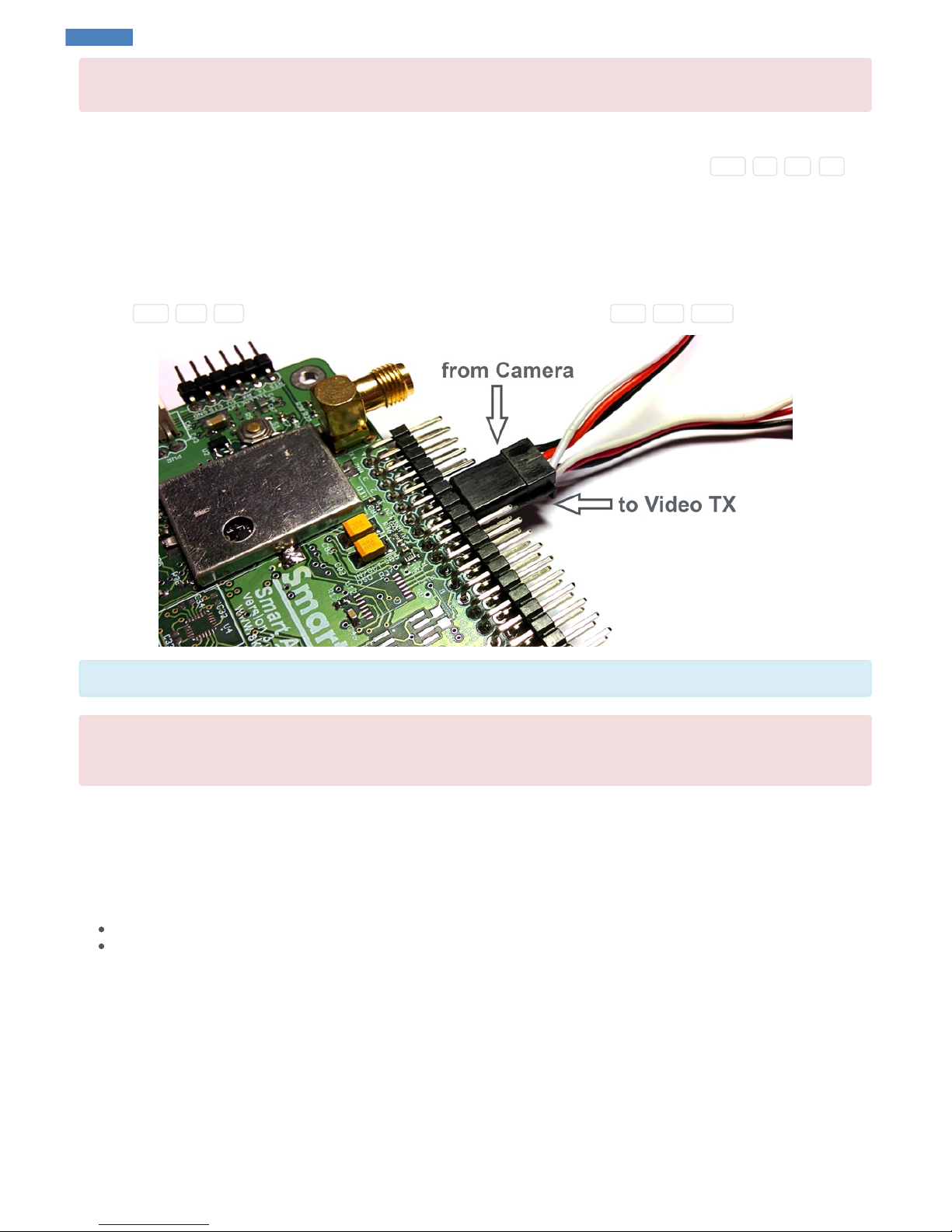
OSD Video
SmartAP has integrated OSD (On-Screen display) module. It means that you can connect your camera output to the autopilot (instead of direct
connection to the video transmitter) and then connect the Video Output of the flight controller to the video transmitter. In this case, the autopilot will
overlay the flight information (mode, altitude, speed, battery status and etc.) on the screen. Connect the video camera to Video IN port of the
autopilot ( GND , 12V , VIN ). Connect the video transmitter to Video OUT port of the autopilot ( GND , 12V , VOUT ).
SmartAP OSD supports both PAL / NTSC video standards with automatic detection and configuration.
Check the voltage ratings for your video camera and video transmitter! SmartAP outputs 12V and normally Camera and Video TX require 12V
power supply, however, some of the cameras / transmitters need 5V or any other specific voltage leve. Check this carefully and provide the
required voltage level. Otherwise, it can damage your Camera / Video TX!
Electromagnetic sounder
Connect Electromagnetic sounder to BUZ port of SmartAP.
Power supply
Connect power supply cable from main power distribution board of the UAV:
SmartAP PRO 0.1 and earlier: 10-36 V, 3S – 8S
SmartAP PRO 0.2 and later: 10-60 V, 3S – 14S
LED & Buzzer
Buzzer: 12V, 0.2A (included in the kit) LED 1-4: 12V, 0.2A per each channel (enough to power LED strip of 25cm length)
Pressure sensor foam
Pressure sensor is highly sensitive to the air pressure noise generated by the props and sunlight. It’s highly recommended to add foam coverage
on pressure sensor to decrease the noise effect and improve measurements which will result in better altitude hold precision. Example is shown
on the picture below:
SmartAP AutoPilot User’s Guide SmartAP PRO
Sky-Drones - SmartAP Flight Control Systems 22 / 89
Page 23
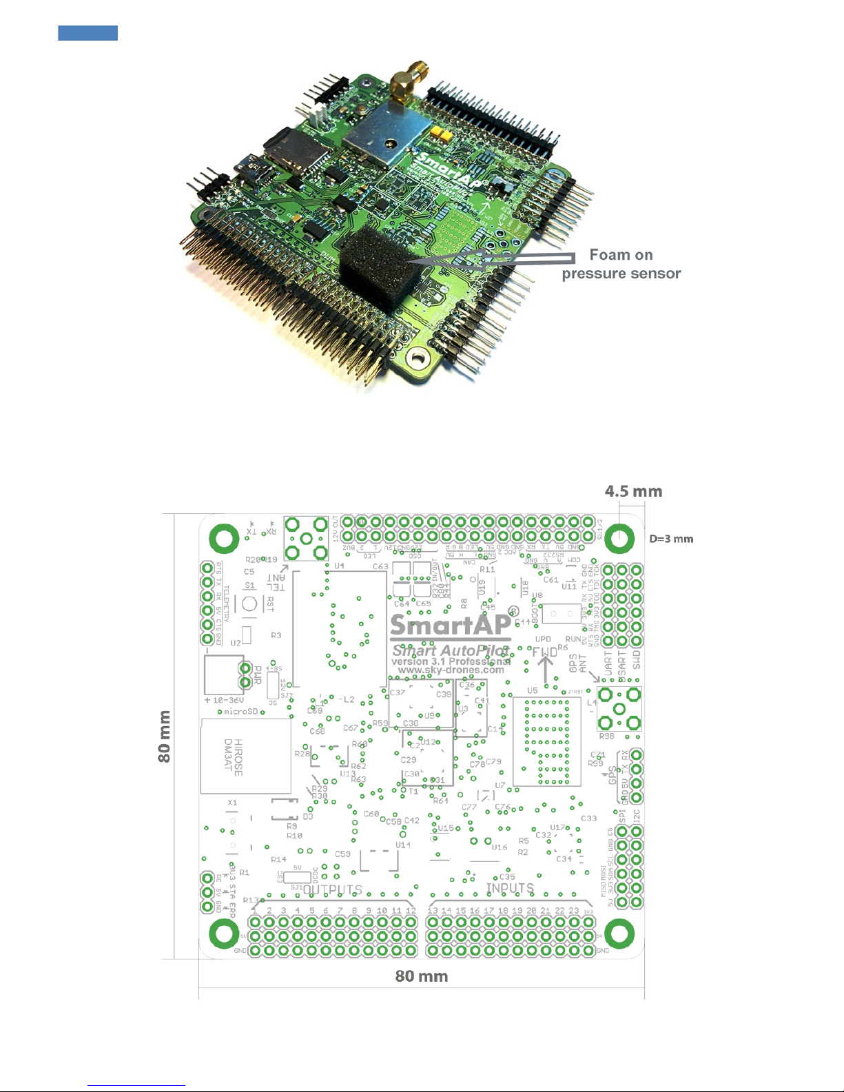
Dimensions
Dimensions of the board are 80x80 mm. Mounting holes diameter is 3 mm, distance between the center of the mounting hole and board edges is
4.5 mm.
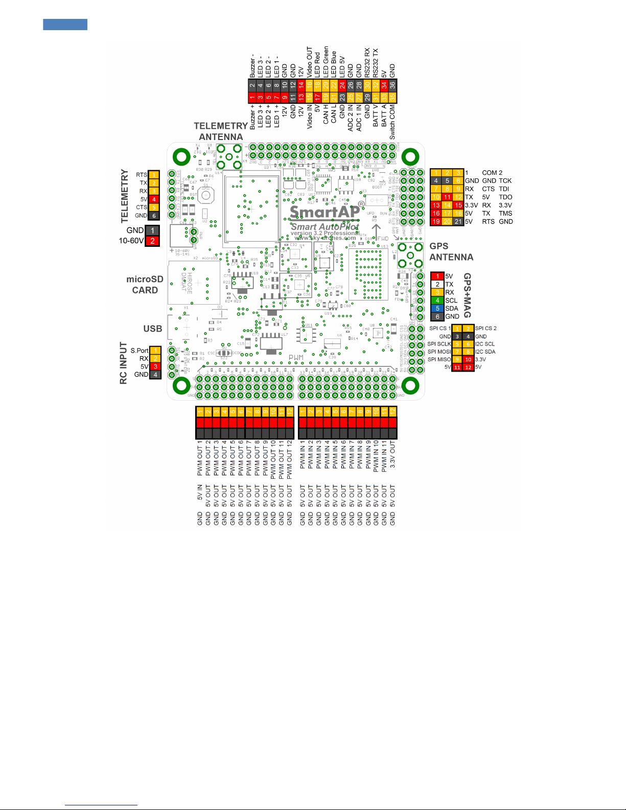
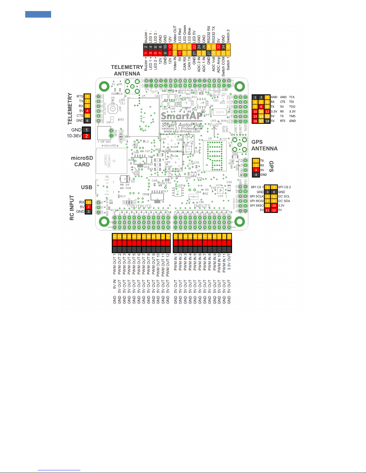
SmartAP PRO v .2 pinout
SmartAP AutoPilot User’s Guide SmartAP PRO
Sky-Drones - SmartAP Flight Control Systems 23 / 89
Page 24
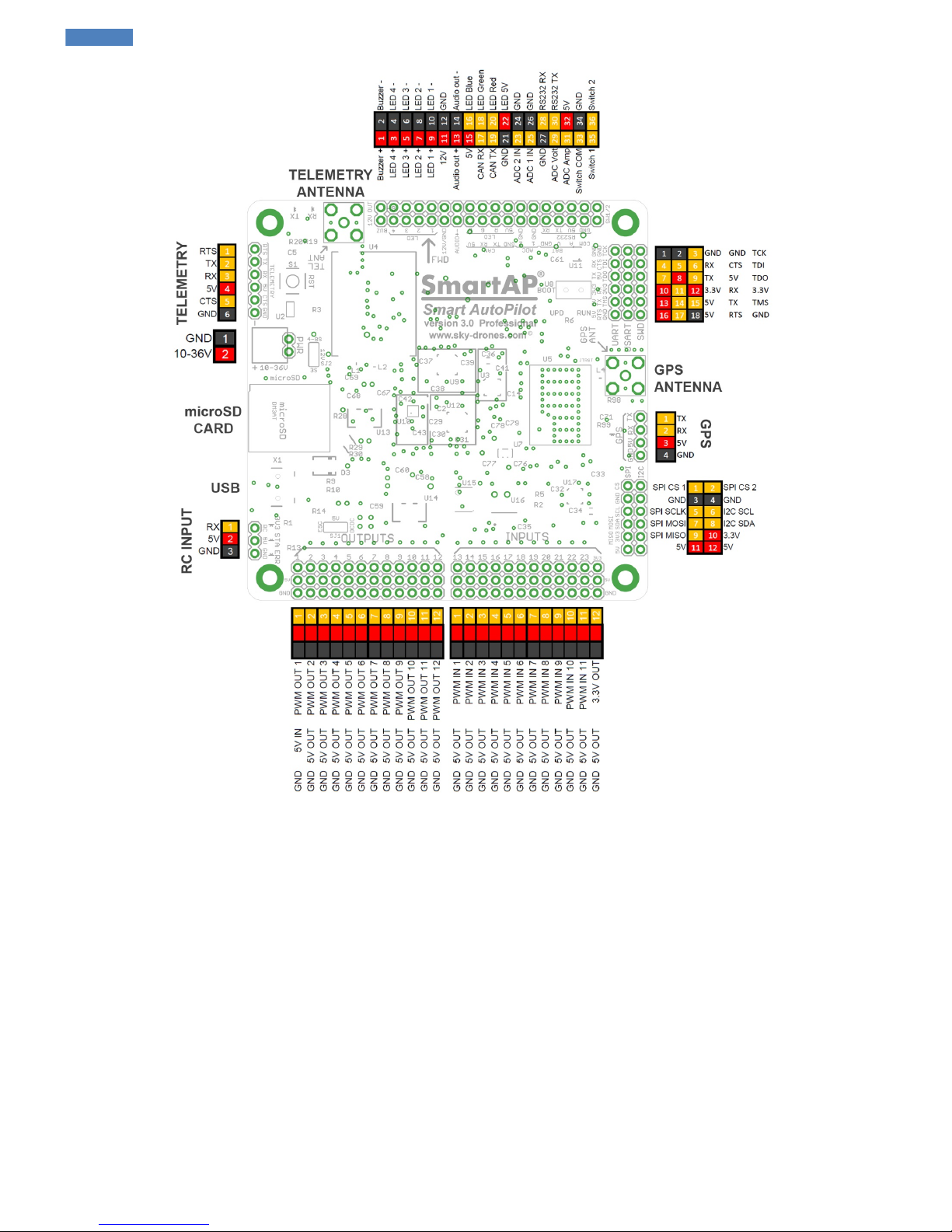
SmartAP PRO v .1 pinout
SmartAP AutoPilot User’s Guide SmartAP PRO
Sky-Drones - SmartAP Flight Control Systems 24 / 89
Page 25
SmartAP PRO v .0 pinout
SmartAP AutoPilot User’s Guide SmartAP PRO
Sky-Drones - SmartAP Flight Control Systems 25 / 89
Page 26
SmartAP AutoPilot User’s Guide SmartAP PRO
Sky-Drones - SmartAP Flight Control Systems 26 / 89
Page 27
SmartAP MAX
Mounting the System
Autopilot
The bottom side of the autopilot has special double-sided foam tape. Remove the protection layer of the anti-vibration tape and mount the
autopilot any direction you want, the actual direction can be selected during configuration procedures later. It’s recommended to mount the
autopilot as close to the center of gravity as possible.
"FRONT" arrow indicates the original flight direction. Can be changed in the settings later.
GNSS / MAG
GNSS Module provides positioning information to the system and is sensitive to EMI noise. Make sure to place GNSS module as far as possible
from:
Main body of the airframe
RF emitting devices, such as video transmitters
High-current cables (ESC / motors power supply)
It’s recommended to use GPS mast for that. Connect the cable and put the GPS on a mast.
Connecting Peripherals
Metal case version
SmartAP AutoPilot User’s Guide SmartAP MAX
Sky-Drones - SmartAP Flight Control Systems 27 / 89
Page 28

Ports pinout for the Front and Rear panels
Front panel connectors pinout:
Rear panel connectors pinout:
Plastic case version
Front panel connectors pinout:
Rear panel connectors pinout:
Make sure NOT to mix up polarity. GND line (black) is always near edge (bottom)
RC Receiver
Connect PPM / SBUS output of the RC receiver to PPM / SBUS Input port of SmartAP.
SmartAP AutoPilot User’s Guide SmartAP MAX
Sky-Drones - SmartAP Flight Control Systems 28 / 89
Page 29

ESC / Motors PWM
Connect ESC cables to SmartAP PWM outputs 1-12 depending on the number of the motors your airframe has. The first motor is always front or
front-right, it’s spinning direction is CCW. Supported airframe types and motors number / spinning direction are shown below.
PWM signals is the top wire, GND is the bottom one.
If you can’t find your airframe in the list above, please, let us know and we’ll add your airframe!
GNSS / MAG
Connect the one side of the cable to GNSS module and the other one to the GPS / MAG port of the autopilot as shown on the pictures below:
Telemetry Module
Connect the one side of the cable to air telemetry module and the other one to the RADIO port of the autopilot as shown on the pictures below:
SmartAP AutoPilot User’s Guide SmartAP MAX
Sky-Drones - SmartAP Flight Control Systems 29 / 89
Page 30

Power Module
Connect power supply cable (10-36 V, 3S – 8S) from main power distribution board of the UAV.
Electromagnetic sounder
Camera trigger
SmartAP MAX supports automated camera triggering interface which physically be:
PWM Output - if you want to use PWM output, simply connect camera trigger activator into any free PWM channel and configure port
number later in the settings.
Relay commutation - if you want to use relay, connect the pins which should be shorted / unshorted upon activation to relay pins RCOM
and ROUT (marked yellow):
SmartAP AutoPilot User’s Guide SmartAP MAX
Sky-Drones - SmartAP Flight Control Systems 30 / 89
Page 31

In case you want to use camera feedback of the moment when the photo was actually taken (for Log file and precise geotagging later) then you
need to connect CS and GND pins marked above to the signal and ground of the interface which provides camera feedback.
Assembled System
Fully assembled and mounted system should look as follows:
SmartAP AutoPilot User’s Guide SmartAP MAX
Sky-Drones - SmartAP Flight Control Systems 31 / 89
Page 32

SmartAP PDB
SmartAP PDB - Power Distribution Board for Batteries / ESCs connection with integrated voltage and current sensors, buzzer, 5V and 12V
outputs.
Pinout
SmartAP Power Distribution Board pinout diagram is shown below. Big pads in the rear side are intended for the main battery connection. Up to
four independent batteries can be connected using the thick wires (e.g. 8-10 AWG) to be able to handle high current loads and even more using
thinner wires. Both top and bottom, left and right sides have pads for ESCs power supply connection. Therefore, up to 12 ESCs can be
connected.
SmartAP AutoPilot User’s Guide SmartAP PDB
Sky-Drones - SmartAP Flight Control Systems 32 / 89
Page 33

Soldering
NOTE
It's strongly recommended to use powerful solder iron (at least 80W), otherwise, there is a high chance of cold joint which can significantly
reduce the reliability.
Soldered Power Distribution Board should look as follows:
SmartAP AutoPilot User’s Guide SmartAP PDB
Sky-Drones - SmartAP Flight Control Systems 33 / 89
Page 34

Powering the autopilot
SmartAP PRO
SmartAP PRO autopilot is capable of getting the power directly from the main battery, therefore, specially dedicated solder terminals can be
used. If you would like the autopilot to get the current sensor (integrated in PDB) readings - simply connect the GND , 5V , CURRENT signals
of the PDB using standard cable to the flight controller.
SmartAP AutoPilot User’s Guide SmartAP PDB
Sky-Drones - SmartAP Flight Control Systems 34 / 89
Page 35

WARNING!
SmartAP 3.x gets power directly from the PDB connected to the main battery, therefore, supply voltage is the same as your battery voltage
and it can be up to:
36V (8S) for SmartAP 3.0
36V (8S) for SmartAP 3.1
Wiring between the Power Distribution Board and the Autopilot should look as following:
SmartAP MAX
SmartAP MAX gets the power supply and voltage / current readings from the PDB using standard 6-pin cable with Molex PicoBlade connectors.
Simply connect the cable to PWR connector of the autopilot.
SmartAP AutoPilot User’s Guide SmartAP PDB
Sky-Drones - SmartAP Flight Control Systems 35 / 89
Page 36

Buzzer support
SmartAP PDB has integrated electromagnetic buzzer (sounder) which is used for audio notifications about the system status. Simply connect the
BUZZER and GND signals of the flight controller to BUZZER and GND signals of the PDB.
Voltage and current sensors
SmartAP PDB has integrated voltage and current sensors. Current sensor is located on the bottom side of the PDB. For correct scale / offset
configuration, please, refer to Configuration section.
SmartAP AutoPilot User’s Guide SmartAP PDB
Sky-Drones - SmartAP Flight Control Systems 36 / 89
Page 37

Drivers installation
Sometimes the operating system can not detect the drivers or detects the drivers incorrectly. If you're experiencing any issues with connecting to
the flight controller or firmware update procedure then you should reinstall the driver.
It's recommended to uninstall all previous drivers associated with the autopilot before proceeding to the next steps.
First of all go to the Device Manager and delete the existing drivers if they are already installed. Then plug in the flight controller into USB port.
You'll see the message that the new device has been discovered:
If you click on the message you'll see more detailed information. The operating system is trying to find the driver for SmartAP Autopilot and its
bootloader.
Most likely the driver won't be found automatically and you need to go to Device Manager and set the correct driver. When you open Device
Manager you'll see SmartAP as unknown device.
If you can not see SmartAP bootloader in the devices list it's probably because the devices is hidden. To make bootloader device visible not
only for initial three seconds after power up but for longer you can enable hidden devices in windows device manager using the steps below.
Open CMD as administrator
Run SET DEVMGR_SHOW_NONPRESENT_DEVICES=1
Type devmgmt.msc to open Device manager
Click View > Show hidden devices
More information and description on the steps above can be found here
SmartAP AutoPilot User’s Guide Drivers installation
Sky-Drones - SmartAP Flight Control Systems 37 / 89
Page 38

Right click on it and choose Update Device Driver .
Then choose Browse my Computer for Driver Software . Go to the Download section of the website and get the driver .inf file for the autopilot.
Specify the location of the driver in Browse menu.
SmartAP AutoPilot User’s Guide Drivers installation
Sky-Drones - SmartAP Flight Control Systems 38 / 89
Page 39

When pop up window comes choose Install driver anyway .
The process might take a few seconds.
SmartAP AutoPilot User’s Guide Drivers installation
Sky-Drones - SmartAP Flight Control Systems 39 / 89
Page 40

Once it's completed you can see the message that the driver was successfully installed.
Unplug and plug in the USB cable of the autopilot to reboot the board and then if you go to Device Manager you'll see that the driver is now
installed successfully:
SmartAP AutoPilot User’s Guide Drivers installation
Sky-Drones - SmartAP Flight Control Systems 40 / 89
Page 41

SmartAP AutoPilot User’s Guide Drivers installation
Sky-Drones - SmartAP Flight Control Systems 41 / 89
Page 42

Getting the software
Go to http://sky-drones.com website to download the all new SmartAP GCS.
This software will help you to configure the autopilot for your specific requirements and prepare it for the flight. The software can be run on all
popular platforms such as:
Desktops
Laptops
Tablets
Smartphones
And available for the major operating systems:
Windows
MacOS
Android
iOS
Linux
Depending on the version and platform you've chosen follow the steps to install the application.
First run
Run the applications after installation and if you're able to see the authorization window then it means that the application was installed
successfully and you may proceed to the next steps.
SmartAP AutoPilot User’s Guide Getting the software
Sky-Drones - SmartAP Flight Control Systems 42 / 89
Page 43

Create account
If you don't have an account yet you'll need to create one. Click SIGN UP and fill the simple form providing your email and password along with
some other details. Account is needed to sync data across your platforms and operating systems and exchange UTM information.
Please, use strong password containing at least 8 symbols with at least one digit.
World pane
Once you fill in the details click SIGN UP . If you're registered successfully you'll get into the app and will see the main pane which is called
World.
SmartAP AutoPilot User’s Guide Getting the software
Sky-Drones - SmartAP Flight Control Systems 43 / 89
Page 44

World pane provides all necessary information about the flight and allows controlling the flight modes and planning the mission.
Toolbar gives the following general information and control:
App Menu
If you pull out the drawer from the left side or click three bars button you'll see the app menu. You can go into your account settings, log out or
switch between the application panes.
UAV Settings
Clicking the gear will open UAV settings menu. The main tab shows information concerning hardware, installed firmware and unique ID. Tabs at
left provide the navigation between various settings of the flight controller which will be described in the further chapters.
SmartAP AutoPilot User’s Guide Getting the software
Sky-Drones - SmartAP Flight Control Systems 44 / 89
Page 45

Links Management
Top right corner has Links icon. Clicking this icon shows connections management menu. There are a few communication types available:
Serial
UDP
TCP / IP
You can create and store a new Serial / UDP / TCP/IP connection by choosing COM Port and Baud Rate or providing IP & Ports details.
Connection can be established via USB or wireless telemetry.
Usually, baud rate for wireless telemetry connection is 57600
If you are about to configure a new Flight Controller unit it is recommended to use USB connection instead of wireless telemetry.
First connection
Select the desired connection, click ADD and then CONNECT .
SmartAP AutoPilot User’s Guide Getting the software
Sky-Drones - SmartAP Flight Control Systems 45 / 89
Page 46

If you have successfully created a proper connection, you will see the icons changing their state and hear confirmation that the UAV has been
connected and parameters are being loaded. Toolbar will show current time, total flight time, radio connection status, GNSS satellites count and
status, link health, battery info and so on.
Sometimes you might get a message that you're using partialy incompatible version. This means that the functionality introduced recently
might be not supported by your currently installed firmware and it's highly recommended to update it.
Therefore, if you see the message above, please, proceed to Firmware Upgrade procedure described in the next chapter.
SmartAP AutoPilot User’s Guide Getting the software
Sky-Drones - SmartAP Flight Control Systems 46 / 89
Page 47

Firmware update
NO BATTERY, USB CONNECTION ONLY!
Do not connect the main battery for the steps below. Use USB connection only!
If you can see exclamation mark icon when pulling out the Drawer it means that there is firmware update available.
Click Firmware and you will see the pane with the information about the latest firmware, upgrade button and progress indicator.
You can click WHAT'S NEW if you want to learn more about the features introduced in this firmware or click UPGRADE to begin procedure.
The firmware will be downloaded from Sky-Drones cloud platform.
Sometimes after pressing the button you might see the reboot request. Simply plug out and then plug in flight controller USB cable.
SmartAP AutoPilot User’s Guide Firmware update
Sky-Drones - SmartAP Flight Control Systems 47 / 89
Page 48

If the upgrade procedure still not started make sure you don't have any other serial (COM port) devices connected to computer.
Once the procedure started you will see progress notification and status. Usually update procedure takes from 30 to 60 seconds.
After upgrade procedure successfully finished you will see the confirmation message.
SmartAP AutoPilot User’s Guide Firmware update
Sky-Drones - SmartAP Flight Control Systems 48 / 89
Page 49

Custom firmware upload
If you want to upload custom firmware you may do that by clicking Options icon (three dots) in the top-right corner. Simply click Custom Firmware
File , select the file you want to flash and follow further instructions.
Getting the log
In case something is not going right during the firmware upgrade you might want to see the logs to further understand the issue or provide this
information to our support team. Simply click Options icon (three dots) in the top-right corner and select Show Update Log .
SmartAP AutoPilot User’s Guide Firmware update
Sky-Drones - SmartAP Flight Control Systems 49 / 89
Page 50

SmartAP AutoPilot User’s Guide Firmware update
Sky-Drones - SmartAP Flight Control Systems 50 / 89
Page 51

General configuration
It's recommended to use USB connection instead of wireless telemetry connection for the steps below.
First of all, connect to the flight controller using links management menu on the top right. Later, click the Gear icon in the left part of toolbar, flight
controller settings popup will appear.
General
General tab provides the major information about the hardware you're using, installed firmware version and unique ID of the flight controller.
Airframe
Airframe tab allows you to configure the type of your vehicle.
Click AIRFRAME and choose your airframe from the list. If you can’t see your airframe there – feel free to contact us and we’ll add the new
airframe type for you.
SmartAP AutoPilot User’s Guide General configuration
Sky-Drones - SmartAP Flight Control Systems 51 / 89
Page 52

Channels mapping and propellers rotation are shown on the corresponding images.
System orientation
You can choose the desired orientation of the flight controller and GNSS Module from corresponding orientation menus.
Landing Gear
SmartAP allows you to configure automatic control of retractable landing gear. Simply select the output channel where servo is connected to and
adjust min / max values. You may apply reverse if needed.
Motors IDLE speed
If you want the motors slightly spinning when the system is Armed you can set Motors IDLE speed to the desired value.
SmartAP AutoPilot User’s Guide General configuration
Sky-Drones - SmartAP Flight Control Systems 52 / 89
Page 53

Radio
Go to RADIO tab and choose the RC receiver protocol corresponding to the one you’re using. SBUS or PPM receivers are recommended. This
change will take effect after the system is restarted. Therefore, you will need to reboot the autopilot and connect again if you want changed to be
applied immediately.
Go to Settings > RADIO again and make sure that your RC radio is turned on. You’ll see the sticks positions displayed. Press CALIBRATE
button and move all sticks and switched of the radio to their end points.
When it’s done – press OK button to stop calibration and save parameters. You can remap any action to the desired channel and apply reverse if
needed.
SmartAP AutoPilot User’s Guide General configuration
Sky-Drones - SmartAP Flight Control Systems 53 / 89
Page 54

Sensors
Sensors configuration tab allows to perform accelerometer, gyroscope and magnetometer calibrations which are very important for excellent flight
performance.
Accelerometer calibration
Click CALIBRATE button near accelerometer data. Click START and follow the instructions which will be shown after procedure started.
SmartAP AutoPilot User’s Guide General configuration
Sky-Drones - SmartAP Flight Control Systems 54 / 89
Page 55

For accelerometer calibration you’ll have to place the autopilot in 6 positions:
Top side up
Top side down
Left side down
Front side down
Right side down
Rear side down
It’s highly important to hold the system still in each position during the calibration. In each step the axis should be aligned with g-acceleration
vector as precise as possible.
Gyroscope calibration
Click CALIBRATE button near gyroscope data. Don’t move the board, put it still, click START and follow the instructions which will be shown
after procedure started.
Magnetometer
Magnetometer calibration is highly important for precise position hold and autonomous flight modes. Make sure that you’re outdoors and don’t
SmartAP AutoPilot User’s Guide General configuration
Sky-Drones - SmartAP Flight Control Systems 55 / 89
Page 56

have any metals around and in your pockets (e.g. keys, cell phones, etc) before calibration. Press CALIBRATE near magnetometer data follow
further instructions. You will need to rotate the vehicle around three major axes (roll, pitch, yaw). After 60 seconds magnetometer calibration will
be automatically completed and pop-up calibration message will go out.
GNSS Configuration
Make sure that the GPS module is connected to the autopilot before proceeding to this step. Also, make sure that the green LED indicating
power supply of the module is solid green.
Sensors tab allows to configure GNSS module with the default parameters and messages required to work properly with SmartAP Autopilots.
Click CONFIGURE button near GNSS data. Click CONFIGURE in the new window again and configuration changes will take an effect after
system reboot.
Battery
Set battery sensor type. The system supports several battery sensors:
Generic power module
SmartAP PDB
SmartAP 3.x internal monitoring
SmartAP AutoPilot User’s Guide General configuration
Sky-Drones - SmartAP Flight Control Systems 56 / 89
Page 57

Custom
Set battery’s cells number and capacity. the system will notify when the charge is too low.
If you're using custom sensor then select Custom and provide the scalers for voltage and current. The scale value can be calculated as follows:
SCALE VALUE = SENSOR RANGE / 4096
Tuning
SmartAP AutoPilot is based on P-PID control algorithm. It means that the stabilization (the ability to stay in the air) and navigation (the ability to
follow desired trajectory) control algorithms include two loops: angle and rates control and position and velocity control. By default the gains
(PIDs) are set to be the average for the majority of airframes, configurations and etc. Of course the parameters can be tuned precisely for better
flight performance.
Here is the brief guide and explanations for PID tuning:
1. Set all values by default.
2. It's very important to tune Stabilization loop as perfect as possible, navigation is based on stabilization, so if it's not well - then the vehicle
will not hover and fly waypoints precisely.
3. The most important parameters are Stabilization Rate Roll / Pitch. Increase it until you see high-frequency oscillations or decrease if you
can already see them. Normally, this value is in between 0.1 – 0.2 depending on your airframe size, motors, ESC, props and vibration
SmartAP AutoPilot User’s Guide General configuration
Sky-Drones - SmartAP Flight Control Systems 57 / 89
Page 58

level.
4. If you can see low-frequency oscillations – it means that your Stabilization Angle Roll / Pitch is too high and you need to decrease it. This
value lays in range between 3 - 6.
Navigation gains can be tuned using the same approach, however, this is not really important to tune this values since they’re fine by default for
the majority of the vehicles.
More information on default gains is available in Standard PID Presets section.
Control
Control tab allows configuring user’s manual control sensitivity, horizontal and vertical speed limits in various modes and failsafe actions.
OSD
OSD tab provides the settings for On-Screen Display module configuration.
In OSD settings you can:
Enable / disable OSD module
Select Metric or Imperial type of the units depending on your preferences
Narrow the overlay area to fit the information on the screen
SmartAP AutoPilot User’s Guide General configuration
Sky-Drones - SmartAP Flight Control Systems 58 / 89
Page 59

Choose specific parameters you would like to be shown
OSD support both PAL and NTSC video standards with auto detection and selection. Typical information layout is shown on the images below:
PAL Layout
NTSC Layout
The actual layout on the screen typically looks as following:
SmartAP AutoPilot User’s Guide General configuration
Sky-Drones - SmartAP Flight Control Systems 59 / 89
Page 60

Camera
Camera tab allows you to configure the camera gimbal and shutter control settings.
Gimbal : The system supports 3-axis gimbal stabilization with flexible configuration for minimum and maximum output angles as well as
minimum and maximum raw output values on the physical layer (PWM is used). As an option, the output can be reversed.
Shutter : Shutter configuration has settings for minimum and maximum output values for the triggering pulse. Interval is the time of how long the
pulse should be in active state to initiate the shutter of the camera to trigger.
SmartAP AutoPilot User’s Guide General configuration
Sky-Drones - SmartAP Flight Control Systems 60 / 89
Page 61

Parameters
Parameters tab gives you direct access to all parameters available in the system.
SmartAP AutoPilot User’s Guide General configuration
Sky-Drones - SmartAP Flight Control Systems 61 / 89
Page 62

Standard PID presets
This section includes default parameters examples for various configuration types. You can find the airframe which suits your mostly and have
parametes value reference for tuning.
MicroDrones MD4-1000 Quadcopter
T960 Hexacopter
SmartAP AutoPilot User’s Guide Standard PID presets
Sky-Drones - SmartAP Flight Control Systems 62 / 89
Page 63

F450 Quadcopter
SmartAP AutoPilot User’s Guide Standard PID presets
Sky-Drones - SmartAP Flight Control Systems 63 / 89
Page 64

3DR Hexacopter
SmartAP AutoPilot User’s Guide Standard PID presets
Sky-Drones - SmartAP Flight Control Systems 64 / 89
Page 65

Updating GNSS Module
Sometimes it might be needed to update the configuration of GNSS receiver. It can be done for both airborne and ground module (RTK GNS).
Latest configuration files as well as configuration tool can be found in the downloads section on the website http://sky-drones.com/dload
Getting U-Center
First of all you need to download and install UBlox U-Center utility. After completing the installation run the program.
RTK GNSS Configuration update
Plug in RTK GNSS Module to the USB port of your computer and make sure that the green LED is solid.
Then go to U-Center utility and setup the connection in the top-left corner: choose the right COM port and set the baud rate to 115200.
Then go to Tools > GNSS Configuration and select the Configuration file (it’s available for download from the website). Set Store configuration
into BBR / Flash checked.
SmartAP AutoPilot User’s Guide Updating GNSS Module
Sky-Drones - SmartAP Flight Control Systems 65 / 89
Page 66

Press File > GNSS button, the update process should start.
If the messages dialog closes itself in about a few seconds and you can’t see any error messages or reports then it means that the configuration
of the GPS receiver has been successfully updated.
SmartAP PRO Onboard GNSS module update
Connect your FTDI cable to the GPS port of the flight controller as following:
GND <-> GND
TX <-> RX
RX <-> TX
Do NOT connect 5V or and power supply pin from FTDI cable to flight controller!
Flight controller will get the power from USB cable. Set the boot switch in UPD (“Update”) mode, connect USB cable to the flight controller and
connect FTDI cable to computer. Your setup should look as follows:
Once the connections are done, please, proceed with the update steps described above.
SmartAP AutoPilot User’s Guide Updating GNSS Module
Sky-Drones - SmartAP Flight Control Systems 66 / 89
Page 67

Troubleshooting: If it seems that there is no connection to GPS module – try to change the TX and RX pins of FTDI cable connected to flight
controller, sometimes colors meanings swapped
Do not forget to put the switch back to RUN position
SmartAP AutoPilot User’s Guide Updating GNSS Module
Sky-Drones - SmartAP Flight Control Systems 67 / 89
Page 68

Modes overview
Flight Modes overview
SmartAP has 3 switches for modes control – one 3-position switch and two 2-position switches:
Mode Switch: 3 position switch (Main mode control):
Stabilize
Altitude hold
Loiter (GPS Position hold + Altitude hold)
Auto Switch: 2 position switch (Auto mode control):
On / Off - enable / disable autonomous waypoints flight (overrides previous switch)
RTH Switch: 2 position switch (RTH mode control):
On / Off - enable / disable return to home mode (overrides both previous switches)
In Altitude Hold and Loiter modes you will have altitude rate control with the throttle stick. Middle position means hold the altitude, raising or
lowering the stick means going up or down with the speed from 0 to 3 m/s (by default, can be changed in Control tab).
Before take off
1. Set your throttle stick down
2. Power on the transmitter
3. Power on the copter
4. Make sure you’re in Stabilize, Altitude hold or Loiter mode
5. When you’re ready to fly – ARM the system by turning left stick right-down for 1 second
6. Release the stick after hearing the long beep
7. The system is armed and ready for take off
The Flight
1. Slowly raise your throttle stick until the copter takes off from the ground
2. Use the right stick to control the lean angles / position of the copter
3. Use mode switches if you want to switch to Loiter / Auto / RTL etc. mode
After landing
1. Disarm the system after landing by turning let stick left-down for a 1 second
2. Two short beeps mean that the system has been successfully disarmed
3. Power off the copter
4. Power off the transmitter
SmartAP AutoPilot User’s Guide Modes overview
Sky-Drones - SmartAP Flight Control Systems 68 / 89
Page 69

Transmitter commands
ARM
Hold for 1 second and release
Performs all calibrations before take off and unlock motors. Long beep followed means that the system is ARMED and ready to fly.
DISARM
Hold for 1 second and release
Locks motors. Two short beeps mean that the system is DISARMED and safe.
Accelerometer calibration
Hold for 3 seconds and release
Short beep means that the system goes into calibration mode. Short positive tone means that the calibration was done and you need to rotate the
vehicle for the next calibration position. Once all six positions are calibrated you’ll hear the tone meaning that the calibration completed
successfully and saved to SD card.
SmartAP AutoPilot User’s Guide Transmitter commands
Sky-Drones - SmartAP Flight Control Systems 69 / 89
Page 70

Gyroscope calibration
Hold for 3 seconds and release
Short beep means that the system starts calibration. DO NOT move the vehicle during the calibration. Short positive tone means that the
calibration was done successfully and saved to SD card.
Magnetometer calibration
Hold for 3 seconds and release
Magnetometer calibration process starts after a beep. Short positive tone after 30 seconds means that the calibration was done successfully and
saved to SD card.
SmartAP AutoPilot User’s Guide Transmitter commands
Sky-Drones - SmartAP Flight Control Systems 70 / 89
Page 71

Flying with SmartAP GCS
World Pane overview
The main pane of the application is called World Pane. Here you can see all general information about the vehicle, switch vehicles, change
modes, plan mission and etc. Here is the brief overview of the information, user interface and control buttons:
Toolbar contains the info about the vehicle status:
Getting the video feed
SmartAP GCS allows to see the real-time video feed right in the application. Click on the Gear icon in the bottom-left corner and select the video
source you would like to use. You can change resolution and apply image rotation if needed.
SmartAP AutoPilot User’s Guide Flying with SmartAP GCS
Sky-Drones - SmartAP Flight Control Systems 71 / 89
Page 72

If you can't see your video source in the list of available devices, make sure to connect the video source to your computer before starting
SmartAP GCS application.
You can also enable full-screen video mode by clicking on the small video window. Map and video widgets will be swaped.
Autonomous Flights
Waypoints flight
Autonomous mission flights are based on waypoints navigation. To create a new mission or choose from the already existing ones simply click
PLANNING button and then click MISSIONS button.
SmartAP AutoPilot User’s Guide Flying with SmartAP GCS
Sky-Drones - SmartAP Flight Control Systems 72 / 89
Page 73

To create a new mission type mission name and click CREATE
To choose the already existing mission click on it
We want to demonstrate creating new mission so we click CREATE now.
Now you can see mission settings menu and Home point icon placed in the center of the map automatically. You can drag home point wherever
you want.
SmartAP AutoPilot User’s Guide Flying with SmartAP GCS
Sky-Drones - SmartAP Flight Control Systems 73 / 89
Page 74

Home point will be overwritten by the initial vehicle location upon the system armed.
To insert new waypoint you just need to double-click on the map.
Mission menu will be automatically switched to Waypoint tab. Individual waypoint settings can be adjusted there.
Altitude : Altitude in meters above takeoff point (home altitude)
Delay : Amount of seconds to hover after reaching the waypoint
Speed : Speed of flying to the next waypoint
Heading : Heading angle in degrees to hold when flying to the next waypoint
When no waypoints selected - those settings are related to default values for new waypoints.
New waypoints can be added by double-clicking on the map:
SmartAP AutoPilot User’s Guide Flying with SmartAP GCS
Sky-Drones - SmartAP Flight Control Systems 74 / 89
Page 75

Of course, waypoints can be:
Adjusted, by dragging them
Deleted, by double-clicking on them
Inserted in-between by double-clickin on path
Waypoint parameters can be adjusted anytime after selecting the desired waypoint to be changed.
The system supports the following waypoint types (Commands) which can be changed by clicking on Command cell for a specific waypoint:
Waypoint: regular point to fly through in air
Take off: start autonomous take off
Landing: perform landing over the point
The system allows creating various mission scenarios – including autonomous take off and / or landing point types or having only waypoints type
in the list:
In the first case the vehicle should be airborne before activating autonomous mode. After AUTO mode was activated the vehicle will start
flying to the first waypoint. If the system is not airborne then the vehicle will not allow switching to the autonomous flight mode.
In the second case the vehicle should be on the ground before activating autonomous mode. After AUTO mode was activated the vehicle
will start autonomous take off and then continue flying to the next waypoint. If the vehicle is airborne before starting AUTO it will skip the
Take off waypoint.
SmartAP AutoPilot User’s Guide Flying with SmartAP GCS
Sky-Drones - SmartAP Flight Control Systems 75 / 89
Page 76

After the mission was created it can be saved and / or uploaded to the vehicle.
If you click UPLOAD then you can notice the status of sending the mission in the right-bottom corner of the application:
Finally, you will see Waypoints Received message.
Before the flight you need to ARM the system. The system can be armed using the RC transmitter stick or by clicking the ARM / DISARM button
in the GCS.
`ARM` command should be confirmed to make sure it wasn't clicked accidentally.
SmartAP AutoPilot User’s Guide Flying with SmartAP GCS
Sky-Drones - SmartAP Flight Control Systems 76 / 89
Page 77

Home position (including altitude) is set on every ARM event. Make sure to ARM the system after it got the stable GNSS satellites signal.
Saving the valid home position and altitude is important for calculating the waypoints altitude.
After you armed the system you can notice the Home icon might moved on the map. This position will be used for RTH (Return to Home) mode
and its altitude will be used as an altitude reference for the waypoints. If you want to change the home position manually you can simply drag &
drop it.
If you don’t have Take off type of the waypoint in your list – you’ll need to take off manually or press TAKE OFF button on the right. After the
vehicle is airborne you can press FLY button or switch to AUTO mode using your RC transmitter. The vehicle will start flying to the first waypoint.
SmartAP AutoPilot User’s Guide Flying with SmartAP GCS
Sky-Drones - SmartAP Flight Control Systems 77 / 89
Page 78

Flight progress can be seen in real-time with the indication of the vehicle path. After the last waypoint reached the vehicle will enter hovering
mode and maintain the altitude and position of the last point or perform landing if it was planned to do so.
Guided flight
Guided flight mode which is also know as "Fly here" mode allows setting and moving the desired position of the vehicle interactively in real-time.
This mode is available only if the vehicle is already flying in the air. To activate the guided flight mode simply click PLANNING button and then
GUIDED button.
Once you clicked on the map the vehicle will start flying to that point and you will see the cross on the map indicating the target position of the
vehicle.
SmartAP AutoPilot User’s Guide Flying with SmartAP GCS
Sky-Drones - SmartAP Flight Control Systems 78 / 89
Page 79

The altitude and speed for the guided point can be set in the Flyhere settings menu on the top-right:
If you want to change the position of the vehicle you can simply drag&drop the cross on the map or right-click on the map and click Fly Here.
Repositioning can be done anytime.
Once the vehicle achieved the target position it starts hoveing at the point awaiting for the other point or flight mode change.
SmartAP AutoPilot User’s Guide Flying with SmartAP GCS
Sky-Drones - SmartAP Flight Control Systems 79 / 89
Page 80

Flying with RTK GNSS
RTK (Real Time Kinematics) - technology which allows increasing GNSS module accuracy to just a few centimeters. SmartAP Autopilots support
RTK GNSS based on UBlox NEO M8P modules. This description demonstrates the procedure of setting up the flight with RTK GNSS.
It's assumed that you already have the following equipment:
RTK GNSS module installed on a drone (also called Rover)
RTK GNSS module as a base station with USB connector
Active patch antenna located on a ground plane (the middle of a car roof is a good choice)
Computer with installed SmartAP GCS
Telemetry modules configured and working on both drone and ground station (telemetry is used to transfer corrections from Base Station
module to Rover)
Locating the antenna
RTK GNSS is very sensitive and needs to be set up carefully.
The base station antenna position should be fixed all time. Please, make sure that it's not moving and has a clear view of the sky far enough from
the buildings and not shadowed by the obstacles. Tripod or a car roof are good locations for base station antenna.
Once you have located the antenna, connect SMA cable to the ground module and plug the module into USB port of the computer.
Solid green LED - Power is on and module is working
Blinking blue LED - GNSS module has 3D position fixed
Connecting in SmartAP GCS
First of all open SmartAP GCS and connect to the drone. Then go to RTK tab in bottom part of the Main Window. Choose the COM port of GNSS
module and press Connect button. Once you're connected you'll see the status of the base station module.
SmartAP AutoPilot User’s Guide Flying with RTK GNSS
Sky-Drones - SmartAP Flight Control Systems 80 / 89
Page 81

Starting Survey-In
Once the base station has enough satellites visible, solid 3D fix and position deviation is not high you can start Survey-In procedure by pressing
Start Survey-In button. This procedure determines the accurate position of the base station based on the measurements. By default, it’s set to
run at least 3 minutes and the accuracy deviation should be less than 1 meter. It's obvious that longer measurements and smaller deviation will
increase the accuracy of corrections sent to the Rover. The measured accuracy and progress are shown on the screen. This process migh take a
few minutes.
3D Accuracy - Positioning accuracy estimation for the last measurement (single measurement) Mean 3D STD - Standard deviation of the
accuracy after Survey-In process started
Survey-In completed
After Survey-In process is completed SmartAP GCS will start sending corrections to the Rover. Survey-In status will change from In Progress to
Completed .
SmartAP AutoPilot User’s Guide Flying with RTK GNSS
Sky-Drones - SmartAP Flight Control Systems 81 / 89
Page 82

If you take a look at the GNSS status of the vehicle shown on the top panel you'll notice the change from GNSS to D-GNSS meaning that the
Rover module gets corrections. D-GNSS mode becomes active after a few seconds since the base station module starts sending corrections.
RTK Modes
RTK has two modes: Float and Fixed . Float mode is easier to reach, usually it becomes available in 30-60 seconds after D-GNSS mode is
active, however, it's less accurate. Later, the system will automatically go to Fixed , accuracy will be higher but the process might take some
time.
What will happen if the Rover looses connection with Base station?
The drone will continue flying, probably with slightly lower accuracy, however, if the connection will not be regained in 60 seconds GNSS module
will go into regular mode. Once the connection is established back the system will be back in RTK mode.
SmartAP AutoPilot User’s Guide Flying with RTK GNSS
Sky-Drones - SmartAP Flight Control Systems 82 / 89
Page 83

Geotag images
SmartAP autopilot along with SmartAP GCS allows to precisely geo tag images for further post-processing. When the camera feedback pin is
connected to the autopilot the autopilot knows the exact moment when the picture was actually taken and writes this information into log file. It
contains the following information:
ID - image sequence number
Latitude - latitude location of the image
Longitude - longitude location of the image
Altitude - altitude of the image (MSL - above mean sea level)
Roll - roll of aircraft
Pitch - pitch of aircraft
Yaw - yaw of aircraft
To geotag images firstly download the log file. Then open SmartAP GCS, pull out the left drawer:
And go to Plot tab:
Click Options menu in top-right corner and click Open log file...
SmartAP AutoPilot User’s Guide Geotag images
Sky-Drones - SmartAP Flight Control Systems 83 / 89
Page 84

Also you can simply drag&drop the desired log file into Logs pane. Once the file open locate CAM_TRIGGER group on the right panel.
And select the checkboxes for the fields you would like to export. Normally, all fields are recommended for further processing. Once selected click Options and click Export CSV .
SmartAP AutoPilot User’s Guide Geotag images
Sky-Drones - SmartAP Flight Control Systems 84 / 89
Page 85

Then you need to select the Folder destination where you want the log file to be exported to. After that you can open the file with any file editor
and check its content:
Later, this information can be used for further post processing and maps stitching.
SmartAP AutoPilot User’s Guide Geotag images
Sky-Drones - SmartAP Flight Control Systems 85 / 89
Page 86

Processing the Logs
Log files are stored on SD card as binary files and they're encoded. However, you can extract the data to understandable text format, basically it's
CSV format which can be later exported in XLS or Matlab or anything else for post-processing and analysis.
You'll need to use the following Python script: ulog2csv.py
Python should be installed on your computer.
If you don't have it yet you can download here https://www.python.org/downloads/, version 2.7.
To export the log follow the steps:
Open command line
Go to the folder where ulog2csv.py script is located cd /path/to/script
Execute the command: python ulog2csv.py filename.ulg where filename.ulg is the path to the log file
You'll see the folder will all log messages splitted in separate files
For instance, if you're interested in GNSS (GPS/GLONASS) data you would need GNSS_REPORT.csv file.
SmartAP AutoPilot User’s Guide Processing the Logs
Sky-Drones - SmartAP Flight Control Systems 86 / 89
Page 87

Support
Safety
Operating a powered vehicle of any kind can be a lot of fun, but it carries certain inherent risks. Regulations governing the use of powered
vehicles, including aircraft, vary from locale to locale, even within the same country or district. It is your responsibility to ensure that you
understand and comply with all local laws and regulations.
Safety basics
Never operate the vehicle or software in a way that could be dangerous to you, other people, or property.
Always keep propeller arcs free of objects and body parts while the vehicle is live.
Keep in mind that software and hardware failures happen. Although we design our products to minimize such issues, you should always
operate with the understanding that a failure could occur at any time and without warning. Accordingly, you should take the appropriate
precautions to minimize danger in case of product failure.
Never use the software or hardware for manned vehicles.
Always operate within local laws and regulations.
Do not operate the aircraft if you are under the age of 16.
Additional safety information
Be sure to maintain safe distances between people and your aircraft.
Never operate your aircraft if your ability to do so with the utmost attention to safety is impaired in any way. Do not operate your aircraft
while tired, under the influence of drugs or alcohol, or otherwise unable to operate it with the highest attention to safety.
Environment conditions can change rapidly and can make operation difficult. If this occurs, land your aircraft and discontinue use
immediately. Do not operate your aircraft if operating conditions are not ideal. This includes, but is not limited to, rain, snow or excessive
wind.
Always ensure the battery cable is disconnected from the aircraft until you are ready to fly, and ensure that your batteries are fully charged
prior to use.
Always turn on the transmitter and ensure the throttle stick is all the way down before connecting the battery.
After landing, disarm your vehicle immediately and disconnect the battery cable.
Do not turn off the transmitter until after you have disconnected the battery.
Always remove the propellers while testing the motors.
When the battery is connected, always assume the vehicle is live and the motors are armed.
Do not attempt to fly longer than the battery’s safe capacity.
Do not operate the vehicle with excess weight attached.
Ensure that all vehicle components are well maintained before each flight. Ensure that components are firmly attached and operating
properly.
Replace any worn or damaged components before each flight. Never operate with any damaged or worn components.
Support
For more information about SmartAP AutoPilot, please, visit http://sky-drones.com website.
If you have any questions, please, feel free to contact us at http://sky-drones.com
Disclaimer
SKY-DRONES RESERVES THE RIGHT TO UPDATE THE WARRANTIES AT ANY TIME WITHOUT EXPRESS NOTICE. SKY-DRONES
MAKES NO OTHER WARRANTIES FOR SKY-DRONES -BRANDED PRODUCTS, AND MAKES NO WARRANTIES WHATSOEVER FOR
SERVICE, SOFTWARE, MAINTENANCE OR SUPPORT FOR NON- SKY-DRONES -BRANDED PRODUCTS. SUCH PRODUCTS,
SOFTWARE, SERVICES, MAINTENANCE OR SUPPORT IS PROVIDED BY SKY-DRONES “AS IS” AND ANY THIRD-PARTY
WARRANTIES, PRODUCTS, SOFTWARE, SERVICES, MAINTENANCE OR SUPPORT ARE PROVIDED BY THE ORIGINAL
MANUFACTURER OR SUPPLIER, NOT BY SKY-DRONES. SKY-DRONES MAKES NO EXPRESS WARRANTIES EXCEPT THOSE
STATED IN. SKY-DRONES OFFERS THE HARDWARE AS-IS AND MAKES NO REPRESENTATIONS OR WARRANTIES OF ANY KIND
CONCERNING THE HARDWARE, EXPRESS, IMPLIED, STATUTORY OR OTHERWISE, INCLUDING, WITHOUT LIMITATION,
WARRANTIES OF TITLE, MERCHANTABILITY, FITNESS FOR A PARTICULAR PURPOSE, NON-INFRINGEMENT, OR THE ABSENCE
OF LATENT OR OTHER DEFECTS, ACCURACY, OR THE PRESENCE OF ABSENCE OF ERRORS, WHETHER OR NOT
DISCOVERABLE. SOME JURISDICTIONS DO NOT ALLOW THE EXCLUSION OF IMPLIED WARRANTIES, SO SUCH EXCLUSION MAY
NOT APPLY TO YOU.EXCEPT TO THE EXTENT REQUIRED BY APPLICABLE LAW, IN NO EVENT WILL SKY-DRONES BE LIABLE TO
YOU ON ANY LEGAL THEORY FOR ANY SPECIAL, INCIDENTAL, CONSEQUENTIAL, PUNITIVE OR EXEMPLARY DAMAGES ARISING
OUT OF THE USE OF THE HARDWARE. SKY-DRONES ACCEPTS NO LIABILITY FOR DAMAGE(S) OR INJURIES INCURRED
DIRECTLY OR INDIRECTLY FROM THE USE OF THIS PRODUCT.
SmartAP AutoPilot User’s Guide Support
Sky-Drones - SmartAP Flight Control Systems 87 / 89
Page 88

SmartAP AutoPilot User’s Guide Support
Sky-Drones - SmartAP Flight Control Systems 88 / 89
Page 89

Revision history
Version Date Description
1.3.3 03.06.2018 - Added info about relay camera trigger and feedback
1.3.2 16.05.2018 - Creating new mission and flying with SmartAP GCS
1.3.1 06.05.2018 - Added information about the latest SmartAP GCS
1.3.0 05.03.2018 - Updated SmartAP GNSS module information
1.2.9 03.01.2018 - Added OSD Layout image
1.2.8 01.11.2017 - Added camera settings to Configurator
1.2.7 28.08.2017 - SmartAP MAX Added
1.2.6 20.08.2017 - Added RSSI section
1.2.5 08.08.2017 - Added logs processing info
1.2.4 21.06.2017 - Added standard PID presets section
1.2.3 09.06.2017 - Info about the foam for pressure sensor updated
1.2.2 06.06.2017 - Added more information on SmartAP 3.2
1.2.1 02.06.2017 - Minor updates on index page
1.1.9 24.05.2017
- Added section about creating Region based
waypoints
1.1.8 21.05.2017 - OSD information updated
1.1.7 15.05.2017 - Added SmartAP 3.2 pinout
1.1.6 12.04.2017 - Minor updates and support of offline PDF version
1.1.5 06.04.2017 - SmartAP GNSS v2 and v3 dimensions added
1.1.4 04.04.2017 - SmartAP 3.x dimensions image added
1.1.3 30.03.2017 - SmartAP Autopilot drivers installation section added
1.1.2 18.02.2017 - SmartAP 3.x PDB connections scheme added
1.1.1 17.02.2017 - SmartAP OSD extended documentation
1.1.0 12.02.2017 - SmartAP RTK GNSS information added
1.0.9 28.01.2017 - SmartAP OSD configuration info added
1.0.8 15.01.2017 - SmartAP PDB specifications added
1.0.7 02.10.2016 - SmartAP GCS for autonomous flight section added
1.0.6 29.03.2016 - Firmware update, GPS module update instructions
1.0.5 15.12.2015 - DFU generation section removed
1.0.4 13.12.2015 - GPS firmware update description
1.0.3 01.10.2015 - External GPS / Magnetometer connections
1.0.2 03.08.2015 - Added pinout description, PID tuning hints
1.0.1 09.12.2014 - Minor fixes in all sections
1.0.0 06.12.2014 - Initial release of the Guide
SmartAP AutoPilot User’s Guide Revision history
Sky-Drones - SmartAP Flight Control Systems 89 / 89
 Loading...